manuals.online logo
Brands
  1. Home
  2. •
  3. Brands
  4. •
  5. Festo
  6. •
  7. Switch
  8. •
  9. Festo CDSM-S1 User manual

Festo CDSM-S1 User manual

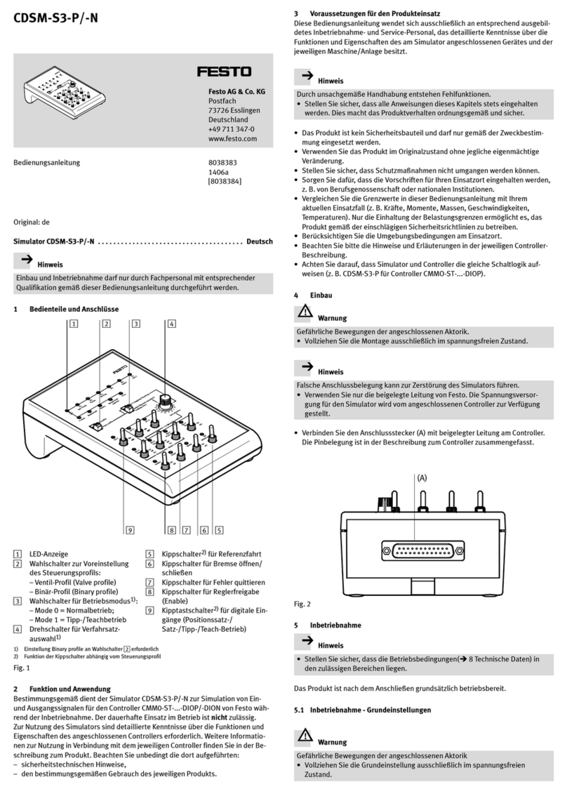
Simulator CDSM-S1
Festo AG & Co. KG
Ruiter Straße 82
73734 Esslingen
Germany
+49 711 347-0
www.festo.com
Operating instructions 8104159
2018-12a
[8104161]
Translation of the original instructions
For all available product documentation èwww.festo.com/pk
1 Operating elements and connections
Fig. 1
72143 5 86
aC aB aJ
aA 9
1Selector switch for limit switches
(external/internal)
2Selector switches for presetting
the controller type CMMS or CMMP
(both switches must be set to the
same type)
3Rotary switch for position set
selection
4Sockets for analogue outputs
(e g. for oscilloscope)
5Potentiometers for setting the
voltage of the analogue inputs
6Selector switches for use as
analogue or digital inputs
7Toggle switches for digital inputs
8Selector switch for use as output
or input
9Toggle switch: Start
aJ Toggle switch for output stage
enable
aA Toggle switch for controller enable
aB Toggle switch for simulation of
limit switches (internal)
aC Toggle switch for digital input Din3
(only for CMMS)
Fig. 2
2 Function and application
The CDSM-S1 simulator is intended for use in simulating input and output signals
for controllers of type CMMS, CMMP and SEC-AC from Festo during commissioning.
Continuous use during operation is not permitted.
In order to use the simulators, you must generally have detailed knowledge of the
functions and features of the connected controller. Further information on use in
conjunction with the relevant controller can be found in the manual for the
product. You must observe the:
– safety precautions and the
– designated use of the product.
3 Safety conditions
Warning
Modification to the signal states and parameters with the simulator can trigger
dangerous movements of the connected actuators.
 Make sure that nobody is in the positioning range of the connected actuators
and be very careful with the parametrising and the manipulation of signal
states.
These operating instructions are directed exclusively at personnel trained in
commissioning and servicing, who have detailed knowledge of the functions and
characteristics of the device connected to the simulator and of the relevant
machine/system.
Note
Improper handling can result in malfunctions.
 Make sure that all the instructions in this chapter are observed. The product
will then function correctly and reliably.
 The product is not a safety component and must only be used as designated.
 Unauthorised product modification is not permitted.
 Make sure that safety measures cannot be ignored.
 Ensure that all applicable national and local safety laws are adhered to.
 Compare the maximum values specified in these operating instructions with
your actual application (e.g. forces, torques, masses, speeds, temperatures).
The product can only be used in accordance with the relevant safety guidelines if
the maximum loading limits are observed.
 Take into consideration the ambient conditions at the location of use.
 Please note the instructions and explanations in the relevant description for the
controllers.
4 Installation
Note
An incorrect connection allocation may destroy the simulator. Use only the
supplied original cable from Festo. The power supply for the simulator is
provided by the connected controller.
 Connect the connectors as follows:
– Connector (A) to controller using supplied cable. The pin allocation is
summarised in the description for the controller.
– Connector (B) for external limit switches.
Fig. 3
(A) (B)
PIN Allocation Connector (B)
124 V (out)
Fig. 4
2Limit switch Limit 1 (external) (in)
30 V (out)
424 V (out)
5Limit switch Limit 0 (external) (in)
60 V (out)
5 Commissioning
Please note
 Make sure that the operating conditions èchapter 8 lie within the permitted
ranges.
The product is ready for operation as soon as it is fitted and electrically and
pneumatically connected.
5.1 Commissioning – basic settings
Warning
The actuators may perform sudden unexpected and dangerous movements.
 Make basic settings only in the de-energised state.
 Slide the selector switches 2, 6and 8into the required basic setting for your
controller type:
Controller CMMS Controller CMMP Controller SEC-AC
2
8
6
2
8
6
2
8
6
Fixed switch setting
Optional switch setting
(èController description for CMMS or CMMP in chapter “Commissioning interfaces”)
5.2 Commissioning – carrying out
Warning
Modification to the signal states and parameters with the simulator can trigger
dangerous movements of the connected actuators.
 Make sure that nobody is in the positioning range of the connected actuators
and be very careful with the parametrising and the manipulation of signal
states.
 Make sure that the toggle switches aJ (output stage enable) and
aA(controller enable) are set to OFF.
1. Energise the controller.
2. Set the toggle switches 7and 9as well as aB and aC, and turn the rotary
switch 3in accordance with your application. For an exact description of the
required signal states, please refer to the description for your controller.
3. Turn the potentiometer 5to the mid-position.
4. First set the toggle switch aJ (output stage enable), then the toggle switch aA
(controller enable) to ON.
5. Check whether the actuators react as expected.
Special case:
CMMS mode for toggle switches 7and aC. Please read the explanation in the
chapter “Interfaces” in the CMMS-ST controller description.
6 Disassembly
Warning
The actuators may perform sudden unexpected and dangerous movements.
 Disconnect the connections only in the de-energised state.
7 Troubleshooting
Fault Possible cause Remedy
Controller does not react as
expected
Wrong controller type set on
CDSM-S1
Set both selector switches 2
to the appropriate controller
type (CMMS or CMMP)
Controller does not react to
analogue or digital input
signals or does not indicate
the signal states
Different settings on simulator
and controller
Compare settings of the
selector switches 6and 8
with the controller type
(èchapter “Commissioning –
basic settings”)
Controller does not react to
start/positioning command
Stop Din 13 is active for CMMS Set toggle switch Din 13 to
inactive (èchapter
“Commissioning – carrying out,
special case”)
Internal/external limit switches
are not detected
Selector switch 1incorrectly
set
Correct switch position
Din3 reacts unexpectedly Rotary switch 3and toggle
switch aC superimposed
Rotary switch 3and toggle
switch aC are switched in
parallel. Set desired function
Controller does not react as
expected to Ain1 or Ain2
Selector switch 6set to
“digital”
Slide selector switch 6to
“analog”
Potentiometer 5turned in the
wrong direction
Potentiometer 5is assigned
in opposite directions for Ain1
and Ain2.
The level increases for Ain1
and decreases for Ain2:
– when turned anti-clockwise
The level increases for Ain2
and decreases for Ain1:
– when turned clockwise
8 Technical specifications
CDSM-S1
Ambient temperature [°C] 0 … +50
Relative air humidity [%] 90 (non-condensing)
Installation position as desired
Protection class IP20
Digital inputs (Out0 … Out3)
Digital outputs (Din0 … Din13)
Analogue inputs (AMon0 … AMon1,
signals to BNC sockets)
Analogue outputs (Ain0 … Ain2)
Is provided by the connected controller
(see documentation for the controller)
Limit switch
– Operating voltage DC [V] 24 ±20 %
– Current Imax
Imin
[mA]
[mA]
100
5 … 8
Dimensions:
– Width [mm] 106
– Depth [mm] 180
– Height [mm] 62
Materials:
– Housing Acrylonitrile butadiene styrene
Weight [g] 340
This manual suits for next models

2

Other Festo Switch manuals

Festo VPEV-1/8-M12 User manual

Festo

Festo VPEV-1/8-M12 User manual

Festo SMT-8-SL-PS-...-B Series User manual

Festo

Festo SMT-8-SL-PS-...-B Series User manual

Festo SME-CDC-DS-24V-SQM8 User manual

Festo

Festo SME-CDC-DS-24V-SQM8 User manual

Festo SME-8-ZS-230V-...-OE Series User manual

Festo

Festo SME-8-ZS-230V-...-OE Series User manual

Festo SMTO-1 C Series User manual

Festo

Festo SMTO-1 C Series User manual

Festo SMEO-2 Series User manual

Festo

Festo SMEO-2 Series User manual

Festo PEV-1/4A-SW27-B-OD User manual

Festo

Festo PEV-1/4A-SW27-B-OD User manual

Festo CAMC-G-S Series User manual

Festo

Festo CAMC-G-S Series User manual

Festo VPE-1/8 User manual

Festo

Festo VPE-1/8 User manual

Festo SRBF-C series User manual

Festo

Festo SRBF-C series User manual

Festo CDSM-S3-P User manual

Festo

Festo CDSM-S3-P User manual

Festo SRBE Series User manual

Festo

Festo SRBE Series User manual

Festo PEV-1/4-B User manual

Festo

Festo PEV-1/4-B User manual

Festo VABF-S4-A2G2 Series User manual

Festo

Festo VABF-S4-A2G2 Series User manual

Festo SRBE C1 Series User manual

Festo

Festo SRBE C1 Series User manual

Festo SME-1-B User manual

Festo

Festo SME-1-B User manual

Festo SMT-10G-...-24V Series User manual

Festo

Festo SMT-10G-...-24V Series User manual

Festo PEV-1/4-B-OD User manual

Festo

Festo PEV-1/4-B-OD User manual

Festo DAPZ AR Series User manual

Festo

Festo DAPZ AR Series User manual

Festo SMT-8 Series User manual

Festo

Festo SMT-8 Series User manual

Festo SMT-CDC-PS-24V-SQM8 User manual

Festo

Festo SMT-CDC-PS-24V-SQM8 User manual

Festo SMPO-1-H-B User manual

Festo

Festo SMPO-1-H-B User manual

Festo SMTSO-8E-PS-M...-LED-24 Series User manual

Festo

Festo SMTSO-8E-PS-M...-LED-24 Series User manual

Festo SMTSO-1 Series User manual

Festo

Festo SMTSO-1 Series User manual

Popular Switch manuals by other brands

GE GuardSwitch 300 Series quick start guide

GE

GE GuardSwitch 300 Series quick start guide

Cabletron Systems SmartSTACK 100 user guide

Cabletron Systems

Cabletron Systems SmartSTACK 100 user guide

EUCHNER CES-I-BP Series operating instructions

EUCHNER

EUCHNER CES-I-BP Series operating instructions

Veris Industries Hawkeye 939 installation guide

Veris Industries

Veris Industries Hawkeye 939 installation guide

Supermicro SSE-G48-TG4 Configuration guide

Supermicro

Supermicro SSE-G48-TG4 Configuration guide

NIVELCO NIVOFLIP MAK-100 Series user manual

NIVELCO

NIVELCO NIVOFLIP MAK-100 Series user manual

FM Systems VLS771-2 installation manual

FM Systems

FM Systems VLS771-2 installation manual

INNOVATIVE CIRCUIT TECHNOLOGY ICT200-LVD instruction manual

INNOVATIVE CIRCUIT TECHNOLOGY

INNOVATIVE CIRCUIT TECHNOLOGY ICT200-LVD instruction manual

TRENDnet TPE-S44 - Switch Quick installation guide

TRENDnet

TRENDnet TPE-S44 - Switch Quick installation guide

EUCHNER TZ AS1 Series operating instructions

EUCHNER

EUCHNER TZ AS1 Series operating instructions

Eaton EGS Series Instruction booklet

Eaton

Eaton EGS Series Instruction booklet

HP P2361AA #ABA user manual

HP

HP P2361AA #ABA user manual

Key Digital KD-X4x1WUTx operating instructions

Key Digital

Key Digital KD-X4x1WUTx operating instructions

ANTAIRA LNP-2602G-SFP Series Quick installation guide

ANTAIRA

ANTAIRA LNP-2602G-SFP Series Quick installation guide

Cisco AJ732A -  MDS 9134 Fabric Switch installation guide

Cisco

Cisco AJ732A - MDS 9134 Fabric Switch installation guide

NETGEAR S350 Series installation guide

NETGEAR

NETGEAR S350 Series installation guide

IPGARD DPMST-4S-P quick start guide

IPGARD

IPGARD DPMST-4S-P quick start guide

Intermatic CA600 user manual

Intermatic

Intermatic CA600 user manual

manuals.online logo
manuals.online logoBrands
  • About & Mission
  • Contact us
  • Privacy Policy
  • Terms and Conditions

Copyright 2025 Manuals.Online. All Rights Reserved.