Manual 35018V2 505XT Digital Control System for Steam Turbines
Woodward 3
Illustrations and Tables
Figure 9-1. DSLC-2 ..................................................................................................................................... 11
Figure 9-2. Configuration/Woodward Links/DSLC-2................................................................................... 12
Figure 9-3. Service Screen - DSLC-2 Power Parameters .......................................................................... 12
Figure 9-4. Service Screen - DSLC-2 Status Parameters .......................................................................... 13
Figure 9-5. VS-II.......................................................................................................................................... 14
Figure 9-6. Configuration/Woodward Links/VS-II ....................................................................................... 14
Figure 9-7. Service/VariStroke II................................................................................................................. 15
Figure 9-8. MFR300 Multi-Function Relay .................................................................................................. 15
Figure 9-9. Configuration/Woodward Links/MFR300.................................................................................. 16
Figure 9-10. Service Screen1/Woodward Links/MFR300........................................................................... 16
Figure 9-11. Service Screen2/Woodward Links/MFR300........................................................................... 17
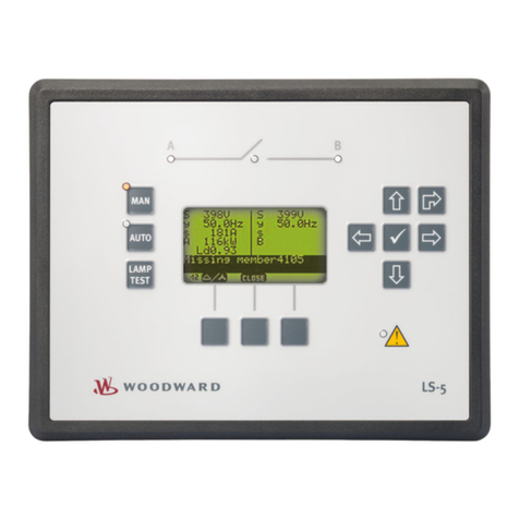
Figure 9-12. LS-5 ........................................................................................................................................ 17
Figure 9-13. Configuration/Woodward Links/LS-5...................................................................................... 18
Figure 9-14. Service Screen/Woodward Links/LS-5................................................................................... 19
Figure 9-15. HighPROTEC ......................................................................................................................... 19
Figure 9-16. Configuration Screen/Woodward Links/HighPROTEC........................................................... 20
Figure 9-17. Service Screen/Woodward Links/HighPROTEC .................................................................... 20
Figure 9-18. Servo Position Controller........................................................................................................ 21
Figure 9-19. Interface to Servo Position Controller..................................................................................... 21
Figure 9-20. Real Power Sensor................................................................................................................. 22
Figure 9-21. EGCP-3 Control...................................................................................................................... 23
Figure 9-22. EGCP-3 LS Functional Diagram............................................................................................. 24
Figure 9-23. EGCP-3 LS Interface Wiring................................................................................................... 25
Figure 9-24. Typical Redundant I/H System with a Transfer Valve............................................................ 26
Figure 9-25. Typical Redundant I/P System with a Pressure Selecting Relay Valve................................ 27
Figure 10-1. Pump or Compressor Discharge Pressure Control with Turbine Inlet Pressure Limiting ...... 31
Figure 10-2. Inlet Pressure Control with Automatic Synchronizing & Generator Power Limiting ............... 34
Figure 10-3. Exhaust Pressure Control with Generator Power Limiting and Plant Import/Export Limiting. 38
Figure 10-4. Plant Import/Export Control with SPC Servo Interface........................................................... 42
Figure 10-5. Inlet Pressure Control with Isochronous Load Sharing Control in Island Mode..................... 46
Figure 10-6. Import/Export Control or Exhaust Pressure Control with Isoch Load Sharing in Island Mode
................................................................................................................................................ 49
Figure 10-7. Pump or Compressor with Discharge Pressure Control and Turbine Inlet Pressure Limiting53
Figure 10-8. Inlet Pressure Control with Automatic Synchronizing & Generator Power Limiting ............... 57
Figure 11-1 505 Keypad and Display.......................................................................................................... 62
Figure 12-1. User Login for Service ............................................................................................................ 65
Figure 12-2. Authorized and Unauthorized Components ........................................................................... 65
Figure 12-3 Service Menu (page 1) ............................................................................................................ 66
Figure 12-4 Service Menu (page 2) ............................................................................................................ 67
Figure 13-1. Proportional Gain Setting Effects ......................................................................................... 100
Figure 13-2. Open Loop Proportional and Integral Response .................................................................. 101
Figure 13-3. Closed Loop Proportional and Integral Response................................................................ 102
Figure 13-4. Integral Gain (Reset) Setting Responses............................................................................. 103
Figure 13-5. Closed Loop Proportional and Derivative Action.................................................................. 104
Figure 13-6. Derivative Setting Effects ..................................................................................................... 105
Figure 13-7. Closed Loop Proportional, Integral and Derivative Action.................................................... 106
Figure 13-8. Typical Response to Load Change ...................................................................................... 107
Figure 13-9. Speed Dynamics for Extraction/Admission type turbine ...................................................... 108
Figure 13-10. Speed Dynamics Generator On-Line Gain Curve.............................................................. 109
Figure 13-11. Speed Dynamics Optimizer ................................................................................................ 110
Figure 13-12. Configuring settings for OPTI_Tune ................................................................................... 111
Figure E-1. SOS........................................................................................................................................ 132
Figure E-2. SOS Install Window ............................................................................................................... 133
Figure E-3. SOS Server status dialog box ................................................................................................ 133
Figure E-4. SOS – New Session box........................................................................................................ 134
Figure E-5. SOS - Enter 505 TCP/IP address .......................................................................................... 134
