BERTHOLD TECHNOLOGIES LB 444 User manual

Density
Meter
LB 444
Id. No 32816BA2
Rev. No.: 04 22.04.03


04/03 347 LB 444
I
Table of Contents
Page
1. OVERVIEW.................................................................................................... 1
2. SYSTEM DESCRIPTION ................................................................................. 2
2.1 Use and Function ................................................................................ 2
2.2 Instrument Configuration (Operating Modes) .......................................... 2
2.3 The Principle of Measurement ............................................................... 3
2.4 Measuring Configuration ...................................................................... 4
3. INSTRUMENT DESCRIPTION ......................................................................... 5
3.1 Radioactive Source ............................................................................. 5
3.2 Shieldings.......................................................................................... 6
3.2.1 Shielding Types LB744... with Manually Operated Lock............................. 6
3.2.2 Shieldings with Pneumatically Operated Lock and Shutter Switch.............. 7
3.2.3 Shieldings for Installation in a Container with Manually Operated Lock....... 8
3.2.4 Shieldings for Installation in a Container with Pneumatically Operated Lock
and Shutter Switch ............................................................................. 9
3.3 Detector .......................................................................................... 10
3.4 Evaluation Unit LB 444 ...................................................................... 10
3.4.1 General Description........................................................................... 10
3.4.2 Display............................................................................................ 11
3.4.3 Keypad Function ............................................................................... 11
3.4.4 Softkeys.......................................................................................... 11
3.4.5 Menu Structure ................................................................................ 11
4. SOFTWARE FUNCTIONS AND SYSTEM CONFIGURATION ............................. 17
4.1 General Data.................................................................................... 17
4.2 Operating Mode ................................................................................ 18
4.3 Parameter ....................................................................................... 19
4.4 Product Data .................................................................................... 22
4.5 Calibrate ......................................................................................... 23
4.6 Live Display ..................................................................................... 26
4.7 Service Menu ................................................................................... 26
4.8 Mass Flow........................................................................................ 26
5. INSTALLATION ........................................................................................... 27
5.1 General Safety Precautions ................................................................ 27
5.2 Installation ...................................................................................... 28
5.2.1 Installation on Pipelines ..................................................................... 28
5.2.2 Installation in a Container .................................................................. 30
5.2.3 Water Cooling Installation .................................................................. 32
5.2.4 Cooling Medium ................................................................................ 33
5.2.5 Installation of Resistance Thermometer Pt 100...................................... 34
5.2.6 Installation of Evaluation Unit ............................................................. 34
5.3 Electrical Connections........................................................................ 35
5.3.1 Detector .......................................................................................... 35
5.3.2 Evaluation Unit LB 444 ...................................................................... 36
6. GETTING STARTED...................................................................................... 38
6.1 Quick Installation Overview ................................................................ 38
6.2 Getting Started................................................................................. 39

04/03 347 LB 444
II
6.2.1 Basic Settings .................................................................................. 41
6.2.2 Calibration ....................................................................................... 42
6.3 Measurement ................................................................................... 44
6.4 Error Messages................................................................................. 45
6.4.1 Error Messages Reset ........................................................................ 45
6.4.2 Error Messages during Operation ........................................................ 45
6.4.3 Error Messages during Calibration ....................................................... 45
6.4.4 Error Messages during Measurement ................................................... 46
6.5 System Start/Stop ............................................................................ 48
7. TEMPERATURE COMPENSATION ................................................................. 49
7.1 Temperature Measurement ................................................................ 49
7.2 Monitoring the Temperature Signal...................................................... 49
7.3 Function of Temperature Compensation ............................................... 50
7.4 Temperature Compensation in Suspensions .......................................... 50
7.5 Calculation of Temperature Coefficients................................................ 50
7.6 Calculation of Square Temperature Coefficient ...................................... 52
7.7 Reference Temperature ..................................................................... 53
7.8 Temperature Coefficient Calculation without Table Values ....................... 53
8. CALIBRATION ............................................................................................. 55
8.1.1 Calibration Modes ............................................................................. 55
8.1.2 One-Point Calibration ........................................................................ 57
8.1.3 Two and Multi-Point Calibration........................................................... 59
8.1.4 Correction of Analysis Values.............................................................. 60
8.1.5 Checking the Calibration .................................................................... 62
8.2 Radiating Interference Detection ......................................................... 63
8.3 Automatic Measuring Time Switchover ................................................. 64
8.4 Measurements of Suspensions ............................................................ 65
8.4.1 Calculating the Density of Individual Components.................................. 68
8.5 Correcting the Results: Addition and Multiplication................................. 69
8.5.1 Additive Constant ............................................................................. 69
8.5.2 Multiplication Factor .......................................................................... 70
9. TECHNICAL DATA ....................................................................................... 71
9.1 Evaluation Unit LB 444 ...................................................................... 71
9.2 Detectors......................................................................................... 72
10. SERVICE INSTRUCTIONS ............................................................................ 74
10.1 General Safety Precautions ................................................................ 74
10.2 Evaluation Unit LB 444 ...................................................................... 74
10.3 Shielding and Source......................................................................... 76
10.4 Service Menu ................................................................................... 77
10.4.1 Overview ......................................................................................... 77
10.4.2 Service Menu ................................................................................... 78
10.4.3 Plateau Check .................................................................................. 79
10.5 Detector .......................................................................................... 82
10.5.1 Checking the Crystal-Multiplier Assembly ............................................. 82
10.6 Replacing the Evaluation Unit LB 444................................................... 84
11. RADIATION PROTECTION ........................................................................... 85
11.1 Basics and Guidelines ........................................................................ 85
11.2 Shielding Installation Safety Instructions.............................................. 87
11.3 Radiation Dose Calculations................................................................ 87

04/03 347 LB 444
III
11.4 Emergency Instructions ..................................................................... 89
12. APPENDIX .................................................................................................. 90
12.1 Absorption Coefficients ...................................................................... 90
12.2 Temperature Coefficients ................................................................... 91
12.3 Density of Water as a Function of the Temperature................................ 92
12.4 Setup Protocol.................................................................................. 93
13. DIMENSIONAL DRAWINGS ......................................................................... 95
13.1 Detectors......................................................................................... 95
13.2 Detectors with FM Certificate .............................................................. 97
13.3 Mounting Device 90° for Pipe Diameter 88.9...304 mm ................................ 98
13.4 Mounting Device 90° for Pipe Diameter 21.3...76.1 mm ............................... 99
13.5 Mounting Device 30 / 45 ° ................................................................100
13.6 LB 444 ...........................................................................................101
14. EX- CERTIFICATES FOR EVALUATION UNIT .................................................. 1
15. EX-CERTIFICATE FOR THE DETECTORS ......................................................... 4

04/03 347 LB 444
IV
List of Figures
Page
Figure 1: Principle of measurement ......................................................... 3
Figure 2: Measuring system mounted on a pipeline.................................... 4
Figure 3: Shielding container type LB744 ................................................. 6
Figure 4: Shielding container type LB 744x with pneumatic locking drive ...... 7
Figure 5: Shielding for installation in a container ....................................... 8
Figure 6: : Pneumatic locking mechanism, not Ex-protected........................ 9
Figure 7 Shutter switch for ex-protected area ........................................... 9
Figure 8: Front Panel LB 444 ................................................................ 10
Figure 9: Softkeys functions ................................................................. 12
Figure 10: Function keys...................................................................... 13
Figure 11: Installation on a horizontal pipeline ........................................ 28
Figure 12: Outdoor installation ............................................................. 29
Figure 13: Installation on S or U-shaped measuring path.......................... 29
Figure 14: External installation of shielding and detector .......................... 30
Figure 15: Installation in a container ..................................................... 30
Figure 16: Installation in a container with horizontal flow ......................... 31
Figure 17: Installation in a container with vertical flow ............................. 31
Figure 18: Installation of water cooling .................................................. 32
Figure 19: Required amount of cooling water .......................................... 33
Figure 20: Cable connections at detector................................................ 35
Figure 21: Terminal connection evaluation unit (rear panel)...................... 36
Figure 22: Rear view of shielding container type LB 744. .......................... 39
Figure 23: Locking mechanism with knurled nut ...................................... 40
Figure 24: Locking mechanism with spring pin ........................................ 40
Figure 25: Influence of absorption coefficients on one-point calibration....... 58
Figure 26: One-point calibration with additional calibration points .............. 58
Figure 27: Example of multi-point calibration.......................................... 59
Figure 28: Response ........................................................................... 64
Figure 29: Density of suspensions ......................................................... 65
Figure 30: Conversion scheme.............................................................. 67
Figure 31: Plateau curve...................................................................... 80
Figure 32: Assembly of scintillation counter ............................................ 82

04/03 347 LB 444
V
Operating Manual Density Meter LB 444
Revision History
No. Date Comments
04 22.04.03 Atex certificates, LB 4430

04/03 347 LB 444
VI
Safety Summary
Electrical Shock Hazard
Disconnect power to ensure that contact with energized part is avoided during installation
and servicing.
Specific Warnings
Never change the installation or the parameter settings without a full knowledge of the
relevant part of this manual, the connected controller and the process, if it is controlled
by this measuring device.
Radiation Protection Instructions
This measuring device utilizes radioactive sources. Local regulations controlling the use of
radioactive sources must be followed. This is the law.
Installation, dismantling, relocation, maintenance, testing involving the radioactive
source or its shielding have to be performed by persons specifically licensed. Radioactive
sources which are not in use have to be stored at a save place which is tamperproof.

04/03 347 LB 444
VII


04/03 347 LB 444
1
1. Overview
The Density Meter LB 444 is designed for density measurements of liquids, suspensions,
pulps and bulk materials. Measurements can be carried out directly in a product line or in
a container.
The density measuring system LB 444 utilizes the radiometric measurement method, i.e.
the attenuation of Gamma radiation passing through the product being measured.
Typically, the measuring system is installed at the measurement location using appropri-
ate installation devices. If you have any questions, please contact the supplier.
Radiometric measuring systems utilize radioactive substances which are manufactured
in compliance with official regulations and which are protected by suitable shieldings.
When handled properly, any hazards to personnel due to radioactive substances can be
ruled out. As prescribed by law, these measuring facilities may be operated only by spe-
cifically licensed persons with sufficient expertise and training.
The hardware and software of the LB 444 system makes it easy to adapt the system to
rather different measuring geometries and measuring tasks. Therefore, the settings and
parameters of the measuring instrument have to be defined with care for the respective
measuring task when taking the system into operation. Important parameters may not
be changed later, in order not to compromise the reliable operation of the system. The
system should be taken into operation and settings changed only by persons who know
how to work with the instrument. Therefore, all users should read these operating in-
structions carefully. We recommend documenting all settings in a setup protocol.
Before starting any work, please read this operating manual carefully!

04/03 347 LB 444
2
2. System Description
2.1 Use and Function
The radiometric density measuring system can be used to measure the density of
•liquids
•suspensions
•pulps and
•bulk goods.
Measurements can be carried out directly in a product line or in a container. They are not
affected by pressure and viscosity fluctuations or the flow rate of the product.
Special instrument configurations and calculations allow you to adapt the density meas-
uring system to the local situation and the conditions of the product being measured.
2.2 Instrument Configuration (Operating Modes)
•Density measurement without temperature compensation (TC)
•Density measurement with temperature compensation
−via Pt 100 or
−via current input
•Suspension measurement with any carrier liquid
−Solid density and liquid density are known
−with or without TC
•Suspension measurement with water as carrier liquid
−Solid density is known
−with water temperature compensation the density of the water and the
solids concentration are taken into account for temperature compensa-
tion
•Mass flow measurement without TC (in connection with a volume flow meter)
•Mass flow measurement with TC via Pt 100 (in connection with a volume flow
meter)
•Backscatter measurement (density measurement in containers where no instal-
lations are possible)
•Measurement modes
•continuous measurement
•discontinuous measurement
−Batch operation via keyboard (press <run> button)
−Batch operation via digital input

04/03 347 LB 444
3
2.3 The Principle of Measurement
The density measurement is based on the irradiation method. It utilizes the physical law
of the attenuation of gamma radiation passing through the product being measured. The
resulting measurement effect is the ratio I/I0between the untenanted radiation I0and
the radiation I which is attenuated by the product being measured. The remaining radia-
tion picked up by the detector (scintillation counter) represents the density of the product
being measured. Figure 1 illustrates the principle of measurement. The radiation is at-
tenuated according to the following formula:
I = I0 * e - µ' * ρ* d
I = Radiation picked up by the detector
I0= Untenanted radiation
µ= Mass attenuation coefficient (absorption coefficient) in cm2/g
ρ= Density of absorbing material in g/cm3
d = Thickness of absorbing material in cm
Figure 1: Principle of measurement
The intensity of the radiation picked up by the detector is also dependent on the distance
between source and detector. As in the case of light, the function involved is a square
function, i.e. doubling the distance reduces the radiation intensity to ¼ if all other condi-
tions remain unchanged.
Assuming a constant distance between source and detector and a fixed measuring path,
the radiation picked up by the detector is only dependent on the density of the material
being measured.
Contamination of the product being measured or the pipeline wall by gamma radiation is
not possible at all.
d
Io I
Source Detector

04/03 347 LB 444
4
2.4 Measuring Configuration
Measuring systems for density, concentration and mass flow measurements typically
comprise the following components:
•Radioactive source (a)
•Shielding container (b)
•Detector (c)
•Evaluation unit LB 444 (d)
•Mounting device (e)
•Connection cable (f)
•Resistance thermometer Pt 100 (option) (g)
•Cooling jacket for detector (option)
The detector’s power supply and the measuring signal (pulses) are transmitted via the
cable connected between detector and evaluation unit.
Figure 2: Measuring system mounted on a pipeline
Different configurations and mounting devices may be required, depending on the meas-
uring tasks, the condition of the product being measured and the containers.
Figure 2 shows a basic setup in a pipeline with Pt 100 resistance thermometer and a 90°
mounting device for density, concentration and mass flow measurement.
45° and 30° mounting devices are available to extend the measuring path.
U or S-shaped measuring paths may be used for smaller pipeline diameters. Measure-
ments in containers are also possible (see 5.2.2).
EG&G BERTHOLD
enter
clear run
BERTHOLD
LB 444 - V 2.10
Density -Met er etc.
enter enter
enter
clear run
347
a, b
e
g
c
e
f

04/03 347 LB 444
5
3. Instrument Description
3.1 Radioactive Source
Radioactive sources for industrial applications are always “encapsulated radioactive sub-
stances” which are tightly welded into a sturdy stainless steel capsule, so that the radio-
active substance cannot leak out. Contamination is therefore ruled out. Moreover, any
activation of the product being measured by the sources used is not possible for physical
reasons.
The following sources can be used for these measuring configurations. 241Am, 60Co, 137Cs.
The following isotopes are primarily used for density measurements:
60Co has a relatively high energy of 1.17 and 1.33 MeV, respectively. It is used for den-
sity measurements over very long distances and/or if the radiation has to pass through
very thick pipe or vessel walls. Its half-life period is 5.27 years.
137Cs is the isotope most frequently used for density measurements. Its energy of 0.660
MeV is sufficient to penetrate commonly used pipe and container walls. Due to the lower
energy, the measuring effect is better than with Co-60. Also, the shielding costs for a Cs-
137 source are lower than for a Co-60 source. The half-life period of Cs-137 is approx.
30 years.
Am-241 is ideally suited for measurement of the concentration of components with high
atomic order (iron, nickel, HCl, etc.) in a carrier medium with low atomic order. Its en-
ergy is 60 keV and its half-life period 433 years.*
Please note the Radiation Protection Guidelines in Chapter 11!
*According to NBS, half-life is defined as: Time for the activity of any particular radioisotope to be reduced to
half its initial value.
04/03 347 LB 444
6
3.2 Shieldings
Typically, the source is firmly installed into the working shielding which includes a radia-
tion exit channel to release the active beam towards the detector. The active beam can
be shielded during transport, installation and servicing.
The shielding function must be checked every six months!
3.2.1 Shielding Types LB744... with Manually Operated Lock
The shielding consists of a cast iron or stainless steel outer shell filled with lead, except
for an exit port blocked by a lead filled moveable shutter. The shutter mechanism con-
sists of a rotatable lead filled cup connected to the outside of the housing by means of a
shaft, secured to a handle. The lead filling of the cup has a cylindrical hole. At one dis-
tinct and defined position of the handle, the hole and source holder are aligned, allowing
the radioactive beam to reach outside via a steel cover plate.
This is the “on” position of the device. At all other shaft positions, the beam exit is
blocked by the lead in the cup. The handle which indicates the open or closed condition
of the shutter can be secured in either position against unauthorized manipulation. Ac-
cess to the source holder is prevented by the handle in both the open and closed posi-
tions.
2 1 7
8
Pb
3 3.1 4 5 6
Figure 3: Shielding container type LB744
1 Shell 4 Radiation source
2 Moveable shutter 5 Source holder
3 Radiation exit channel, “OPEN” 6 Locking lever
3.1 Radiation exit channel, “CLOSED” 7 Lock
8 Cover plate

04/03 347 LB 444
7
3.2.2 Shieldings with Pneumatically Operated Lock and
Shutter Switch
NOTE: Option not available in the USA.
A pneumatic lock with switch contacts indicating the position of the lock is available as a
special version.
The pressurized air moves the shutter to the OPEN position. If the pressurized air is
turned off or in case of failure the moveable shutter is turned back to the CLOSED posi-
tion by the spiral spring.
Pressurized air:
min. 4*105 Pa (4 kp/cm2)
max. 7*105 Pa (7 kp/cm2)
Shutter switch:
IP 65
max. 250 V,
40 VA, 1 A
Air quality
clean, as usual for pressurized
air tools, oil free
Temperature range:
-5 to + 60°C
CAUTION-
RADIOACTIVE
MATERIAL
Throttle
valve
Pressurized air
connection
Spring unit
Drive
Shutter
switch
Figure 4: Shielding container type LB 744x with pneumatic locking drive
Do not open spring unit. DANGER!
The pneumatic drive is equipped with a throttle valve. The valve must be set
such that the shielding’s opening and closing process takes at least 2 s; other-
wise the shielding may get damaged!

04/03 347 LB 444
8
3.2.3 Shieldings for Installation in a Container with
Manually Operated Lock
The shielding consists of a lead-filled
steel pipe, with a guide tube for the ra-
dioactive source installed in the center.
The radiation exit channel is located in
an angle of 90° or 45° relative to the
longitudinal axis.
After taking off the covering cap which is
secured by a lock you may open the
knurled screw and, using the stay bar,
move the radioactive source forward
(OPEN) or back (CLOSED).
Locking
mechanism
Covering cap
Lead
Source position
CLOSED
Steel pipe
Protection pipe
Source position
OPEN
Radiation exit
channel
45°
90°
Figure 5:
Shielding for installation in a container

04/03 347 LB 444
9
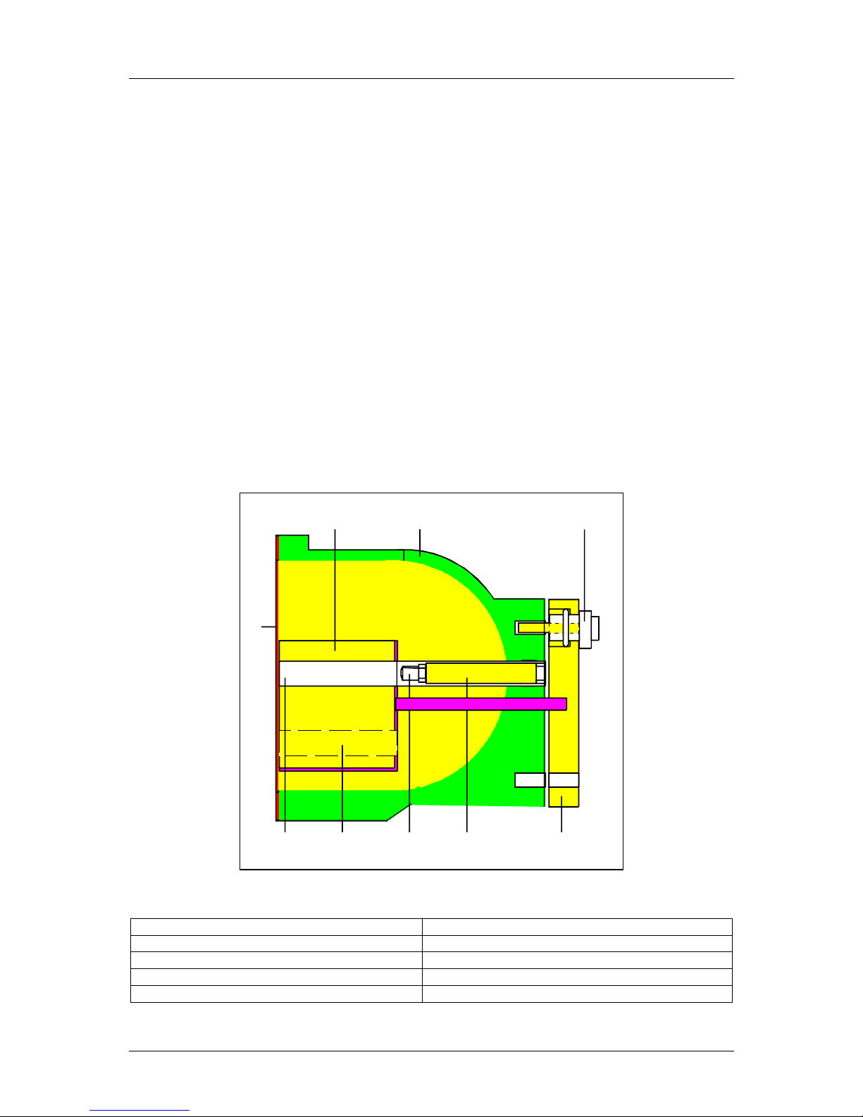
3.2.4 Shieldings for Installation in a Container with
Pneumatically Operated Lock and Shutter Switch
NOTE: Option not available in the USA.
A shielding with a pneumatic lock and
shutter switch is available as a special
version. The pressurized air moves the
source lever to the OPEN position. If the
pressurized air is turned off, or in case
of failure, the spring installed in the
pneumatic cylinder moves the source
back to CLOSED
Pressurized air:
min. 1*105 Pa (1 kp/cm2)
max. 6*105 Pa (6 kp/cm2)
Air quality
clean, as usual for pressurized
air tools, oil free
Closed
Open
Switch CLOSED
Switch OPEN
Cover cap
Connection for
pressurized air electr. signal
OPEN/CLOSED
Figure 6: : Pneumatic locking mecha-
nism, not Ex-protected
Shutter switches signal the position of the
sources.
Two versions are available:
a) Version for use in areas not endan-
gered of explosion:
2 Reed contacts max. 250 V, 40
VA
1 x for OPEN, 1 x for CLOSED.
b) Version for use in the areas endan-
gered of explosion:
1 proximity switch for position
CLOSED.
It has to be connected to a fail-safe power
supply.
Figure 7 Shutter switch for ex-protected
area
See the drawings which are part of the
documentation for detailed information on
the construction and function of the shield-
ing type used.
Closed
Open
Switch flag
Cover cap
C
onnec
ti
on
f
or
pressurized air electr. signal
OPEN/CLOSED
Proximity
switch

04/03 347 LB 444
10
3.3 Detector
A scintillation counter is used as detector.
The detector converts the gamma radiation picked up into electrical pulses. The count
rate transmitted to the evaluation unit is proportional to the radiation intensity received.
The detector is equipped with an automatic drift compensation which automatically cor-
rects component aging and temperature influences, ensuring a high long-term stability of
the measuring system.
The power supply of the detector is carried out via the fail-safe connection circuit of the
LB 444 evaluation unit.
The detector itself includes a fail-safe connection circuit to which a resistance thermome-
ter Pt 100 can be connected for measurement of the product temperature.
The detector assembly in a sturdy stainless steel housing protects the instrument against
normal ambient pollution in industrial applications.
The detector must not be subject to heavy mechanical stress or vibrations.
For more information on its function see chapter 1.
The ambient temperatures must not exceed 50°C; otherwise adequate cooling has to be
provided (see also chapter 5.2.3).
3.4 Evaluation Unit LB 444
3.4.1 General Description
The evaluation electronics is
designed as a 19" module. It
includes the microprocessor-
controlled evaluation elec-
tronics and the power supply
for the required operating
voltage. A 32 bit microproc-
essor featuring a menu-
structured software specially
designed for density meas-
urements is used for signal
processing.
enter
clear run
BERTHOLD
LB 444 - 1 V 1.0
Density -Meter more
enter enter
enter
clear run
LCD display
Softkeys
Function keys
Figure 8: Front Panel LB 444
Table of contents
Other BERTHOLD TECHNOLOGIES Measuring Instrument manuals

BERTHOLD TECHNOLOGIES
BERTHOLD TECHNOLOGIES LB 567 User manual

BERTHOLD TECHNOLOGIES
BERTHOLD TECHNOLOGIES FlowStar2 LB 514 User manual

BERTHOLD TECHNOLOGIES
BERTHOLD TECHNOLOGIES LB 480 User manual

BERTHOLD TECHNOLOGIES
BERTHOLD TECHNOLOGIES LB 124 Scint Series User manual

BERTHOLD TECHNOLOGIES
BERTHOLD TECHNOLOGIES Uni-Probe LB 490 User manual

BERTHOLD TECHNOLOGIES
BERTHOLD TECHNOLOGIES LB 379 User manual

BERTHOLD TECHNOLOGIES
BERTHOLD TECHNOLOGIES Junior LB 9509 User manual


