Berthold LB 444 User manual

i
OPERATING MANUAL
DENSITY METER LB 444
Table of Contents Page
1. INTRODUCTION....................................................................................................... 1
1.1 Safety Summary .............................................................................................1
1.2 Overview.........................................................................................................2
2. SYSTEM DESCRIPTION..........................................................................................3
2.1 Use and Function............................................................................................3
2.2 The Principle of Measurement........................................................................4
2.3 Measuring Configuration.................................................................................5
2.4 Instrument Description....................................................................................7
Radioactive Source......................................................................................... 7
Shieldings ....................................................................................................... 8
2.4.1.1 Shielding Types LB744............................................................ 8
2.4.1.2 Shieldings for Installation in a Container.................................9
Detector ........................................................................................................11
Evaluation Unit LB 444 .................................................................................12
2.4.1.3 General Description...............................................................12
2.4.1.4 Display...................................................................................13
2.4.1.5 Keypad Function....................................................................13
2.4.1.6 Menu Structure (Flow Chart) ................................................. 14
2.5 Software Functions and System Configuration ............................................15
3. INSTALLATION...................................................................................................... 26
3.1 General Safety Precautions..........................................................................26
3.2 Installation.....................................................................................................27
Installation on Pipelines................................................................................27
Installation in a Container or Tank................................................................ 31
3.3 Installation of Water Cooling.........................................................................33
3.4 Installation of Resistance Thermometer Pt 100............................................35
3.5 Installation of Evaluation Unit .......................................................................35
4. CONNECTIONS...................................................................................................... 36
4.1 Detector ........................................................................................................36
4.2 Evaluation Unit LB 444 .................................................................................37
5. GETTING STARTED..............................................................................................39
5.1 Quick Installation Overview .......................................................................... 39
Getting Started........................................................................................................40
Opening the Radiation Exit Channel............................................................. 40
5.1.1.1 Shielding Container Type LB 744..........................................40
5.1.1.2 Shielding Container for Installation in a Container ................41

Density Meter LB 444 Table of Contents
ii
Calibration and Connection of Pt 100 Resistance Thermometer............................43
Basic Settings............................................................................................... 43
Calibration.....................................................................................................46
5.1.1.3 One-point Calibration.............................................................46
5.1.1.4 Two- and Multi-Point Calibration ...........................................47
5.2 Measurement................................................................................................ 49
5.3 Error Messages............................................................................................. 50
Resetting Error Messages ............................................................................50
Error Messages during Operation.................................................................50
Error Messages during Calibration...............................................................50
Error Messages during Measurement .......................................................... 51
5.4 Starting/Stopping Operation of the System ..................................................52
6. BASICS OF DENSITY MEASUREMENTS............................................................53
6.1 Temperature Compensation.........................................................................53
Temperature Measurement..........................................................................53
Monitoring the Temperature Signal ..............................................................53
Function of Temperature Compensation...................................................... 54
Calculation of the Temperature Coefficients ................................................54
Calculation of the Square Temperature Coefficient......................................56
Reference Temperature................................................................................ 57
Temperature Coefficient Calculation without Table Values..........................57
6.1.1.1 Linear temperature coefficient...............................................57
6.1.1.2 Square Temperature Coefficient ...........................................58
6.2 Calibration Method........................................................................................ 59
Calibration Modes.........................................................................................59
One-Point Calibration ...................................................................................61
Two and Multi-Point Calibration....................................................................64
Correction of Analysis Values.......................................................................65
Checking the Calibration...............................................................................67
6.2.1.1 One-Point Calibration ............................................................67
6.2.1.2 Two-Point Calibration ............................................................ 67
6.2.1.3 Multi-Point Calibration............................................................68
6.3 Interference Radiation Detection..................................................................69
6.4 Automatic Measuring Time Switchover ........................................................ 70
6.5 Measurements of Suspensions and Solutions .............................................71
Measurement................................................................................................ 71
Calculating the Density of Individual Components.......................................73
6.6 Correcting the Results: Addition and Multiplication......................................75
Additive Constant..........................................................................................75
6.6.2 Multiplication Factor.............................................................................75
7. TECHNICAL DATA ................................................................................................ 77
7.1 Evaluation Unit LB 444 .................................................................................77
7.2 Detector ........................................................................................................79
8. SERVICE INSTRUCTIONS .................................................................................... 81
9. RADIATION PROTECTION ...................................................................................82
9.1 Basics and Guidelines ..................................................................................82
Shielding Installation.....................................................................................85
Point Source Replacement...........................................................................85
9.2 Radiation Dose Calculations......................................................................... 87
9.2.1 Exposure when Installing the Shielding............................................... 88
9.2.2 Exposure when Replacing Point Sources ...........................................88
9.3 Emergency Instructions ................................................................................90

Density Meter LB 444 Table of Contents
iii
10. APPENDIX.............................................................................................................. 91
10.1 Configuration Checklist.................................................................................91
10.2 Parameter Protocol.......................................................................................92
10.3 Absorption Coefficients.................................................................................93
10.4 Temperature Coefficients .............................................................................93
10.5 Density of Water as a Function of the Temperature.....................................96
10.6 Setup Protocol .............................................................................................. 97
10.7 Wiring Diagram...........................................................................................100
10.8 Dimensional Drawings................................................................................101
10.9 Index ............................................................................................................. 105

Density Meter LB 444 List of Figures
iv
List of Figures
Page
Figure 1: Principle of measurement ....................................................................................4
Figure 2: Measuring system mounted on a straight pipeline ..............................................5
Figure 3: Installation on a U-shaped measuring path .........................................................6
Figure 4: Shielding container type LB744...........................................................................8
Figure 5: Shielding for installation in a container ................................................................9
Figure 6: Shutter switch for ex-protected area..................................................................10
Figure 7: Scintillation counter............................................................................................11
Figure 8: Front Panel LB 444............................................................................................12
Figure 9: Softkeys functions.............................................................................................. 13
Figure 10: Live display ......................................................................................................13
Figure 11: Diagram illustrating the hysteresis...................................................................19
Figure 12: Installation on a horizontal pipeline..................................................................27
Figure 13: Outdoor installation.......................................................................................... 28
Figure 14: Installation on S or U-shaped measuring path.................................................29
Figure 15: External installation with shielding and detector..............................................30
Figure 16: Installation in a container .................................................................................31
Figure 17: Installation in a container with horizontal flow..................................................32
Figure 18: Installation in a container with vertical flow......................................................32
Figure 19: Installation of water-cooling .............................................................................33
Figure 20: Required amount of water-cooling...................................................................34
Figure 21: Cable connections at detector .........................................................................36
Figure 22: Terminal connection evaluation unit (rear panel).............................................37
Figure 23: Rear view of shielding container type LB 744..................................................40
Figure 24: Locking mechanism with knurled nut...............................................................41
Figure 25: Locking mechanism with spring pin.................................................................42
Figure 26: Influence of absorption coefficients on one-point calibration...........................63
Figure 27: One-point calibration with additional calibration points....................................63
Figure 28: Example of multi-point calibration....................................................................64
Figure 29: Response.........................................................................................................70
Figure 30: Source holder...................................................................................................86

v
OPERATING MANUAL
DENSITY METER LB 444
Revision History
Revision No. Date Comments
4 3/7/99 USA Version
5 2/15/00 USA Version

Density Meter LB 444 SECTION 1. INTRODUCTION
1
1. INTRODUCTION
1.1 Safety Summary
Electrical Shock Hazard
Disconnect power during installation and before servicing.
Never change the installation or the parameter settings without a
full knowledge of the relevant part of this manual, the connected
controller and the process controlled by this measuring device.
This measuring device utilizes radioactive sources. Strict compli-
ance to the rules of Radiation Protection and regulations governing
the use of radioactive sources is mandatory.
Installation, dismantling, relocation, maintenance or testing involv-
ing the radioactive source or its shielding, may ONLY be performed
by persons specifically licensed by the US Nuclear Regulatory
Commission or an Agreement State.
GENERAL WARNINGS
SPECIFIC WARNINGS
SPECIFIC CAUTIONS

Density Meter LB 444 SECTION 1. INTRODUCTION
2
1.2 Overview
The Density Meter LB 444 is designed for density measurements of liquids, sus-
pensions, pulps and bulk materials. The measurement may be made directly in-
line or in a product container or tank.
The density measuring system LB 444 utilizes the radiometric measurement
method, i.e. the attenuation of Gamma radiation passing through the product
being measured.
In order to obtain the optimum measurement effect at a minimum source activity,
the measurement geometry is optimized for the specific measuring location and
the source is designed accordingly. The installation details and the source and
detector design are specified when preparing the quotation, and documented by
drawings, sketches and descriptions. To ensure the proper function of the
measurement, it is therefore important to observe these documents closely
when installing the shielding with the source and positioning the detectors.
Radiometric measuring systems utilize radioactive substances which are
manufactured in compliance with regulations and which are protected by suit-
able shieldings. When handled properly, no hazard to persons due to normal
operation of the device exists.
The hardware and software of the LB 444 system makes it easy to adapt the
system to a variety of measurement geometries and measuring tasks. There-
fore, the settings and parameters of the measuring instrument must be defined
with care for each specific measuring task when commissioning the system. Im-
portant parameters may not easily be changed once the system is operational.
The system should commissioned and set-up only by persons who are familiar
with the instrument. Therefore, all users should read these operating instructions
carefully. In addition, we recommend documenting all settings in a setup proto-
col (see Appendix).
This instruction manual describes several measuring configurations and instru-
ment versions. The optimum system configuration is selected for each measur-
ing task during the planning stage. Therefore, the specific project documentation
must be used to configure the system.
Before starting any work, please read this operating manual carefully!

Density Meter LB 444 SECTION 2. SYSTEM DESCRIPTION
3
2. SYSTEM DESCRIPTION
2.1 Use and Function
The radiometric density measuring system can be used to measure the density
of
•liquids
•suspensions
•pulps and
•bulk goods.
The measurement can made directly in-line or in a tank or container. Pressure
and viscosity fluctuations or the flow rate of the product does not affect meas-
urement accuracy.
Special instrument configurations and calculations allow the measuring system
to be tailored to the local needs and conditions of the product being measured:
a) Instrument configuration (Operating modes)
•Density measurement without temperature compensation (TC)
•Density measurement with temperature compensation via Pt 100
•Density measurement with temperature compensation via current input
•Suspension measurement with any carrier liquid
Solids density and liquid density are known
With or without TC
•Suspension measurement with water as carrier liquid
- Solids density is known
- with water temperature compensation
♦the density of the water and
♦the solids concentration
are used for temperature compensation
•Mass flow measurement without TC
•Mass flow measurement with TC via Pt 100
b) Special configuration
•Back-scatter measurement
c) Selection of measurement mode
•Continuous measurement
•Discontinuous measurement
- Batch operation via keyboard (press <run> button)
- Batch operation via digital input

Density Meter LB 444 SECTION 2. SYSTEM DESCRIPTION
4
2.2 The Principle of Measurement
The density measurement is based on the irradiation method. It utilizes the
physical law of the attenuation of gamma radiation passing through the product
being measured. The resulting measurement effect is the ratio I/I0between the
un-attenuated radiation I0and the radiation I which is attenuated by the product
being measured. The remaining radiation picked up by the detector (scintillation
counter) represents the density of the product being measured. Figure 1 illus-
trates the principle of measurement. The radiation is attenuated according to the
following formula:
I = I0 * e - µ' * ρ* d
I = Radiation picked up by the detector
I0= Un-attenuated radiation
µ= Mass attenuation coefficient (absorption coefficient) in cm2/g
ρ= Density of the absorbing material in g/cm3
d = Thickness of the absorbing material in cm
Source Detector
ρ
ρρ
ρI
d
I0
Figure 1: Principle of measurement
The intensity of the radiation picked up by the detector is also dependent on the
distance between source and detector. As in the case of light, the function in-
volved is a square function, i.e. doubling the distance reduces the radiation in-
tensity to ¼ if all other conditions remain the same.
Assuming a constant distance between source and detector and a fixed meas-
uring path, the radiation picked up by the detector is only dependent on the den-
sity of the material to be measured.
NO contamination of the product being measured or of the pipeline wall by
gamma radiation is possible. (Physics).

Density Meter LB 444 SECTION 2. SYSTEM DESCRIPTION
5
2.3 Measuring Configuration
To cover a desired measurement range continuously, a configuration must be
realized where the dimensions of source and detector cover a measuring field of
equal size. The different options available to accomplish this are described be-
low.
The specific arrangement chosen depends on the measurement range and on
the geometry resulting from the measuring task. Moreover, construction factors
and customer-specific requirements may have an effect on the instrument se-
lection. The specific choices and selections are made during the planning stage
and must be implemented during assembly and commissioning.
A measuring system for density, concentration and mass flow measurements
typically comprises the following components:
a) Radioactive source
b) Shielding container
c) Detector
d) Evaluation unit LB 444
e) Mounting device
f) Connection cable
g) Resistance thermometer Pt 100 (option)
h) Cooling jacket for detector (option)
Detector power and output signals use a common two-wire cable connected
between detector and evaluation unit.
Different configurations and mounting devices may be required, depending on
the measurement tasks, the condition of the product being measured and the
pipe or container.
“Fehler! Verweisquelle konnte nicht gefunden werden.Shows a basic setup
in a pipeline with Pt-100 resistance-thermometer and a 90°-mounting device for
density, concentration and mass-flow measurement.
Figure 2: Measuring system mounted on a straight pipeline
enter
clear run
BERTHOLD
Shielding
Container
Pipeline
Evaluation unit
Detector
Pt 100

Density Meter LB 444 SECTION 2. SYSTEM DESCRIPTION
6
45° and 30° mounting devices are available to extend the measuring path (see
enclosed Technical Information LB 444).
The detector-source arrangement may vary depending on the measuring path. If
measuring paths have the shape of a U or S the shielding must be installed at
the top, the detector at the bottom, as shown in Figure 3.
RADIOACTIVE
Figure 3: Installation on a U-shaped measuring path
The system may have to be installed on external supports when the heat insu-
lating material of the pipeline does not allow safe installation (e.g. glass and rock
wool) or when strong vibrations are likely to damage the detector. For further
explanation see section 3. INSTALLATION.
For all installations, precautions must be taken to prevent persons reach-
ing into the active beam.
Measurements in Containers
Density or concentration measurements can also be carried out in a tank or
container and for this purpose, the source in a shielding is installed into a pro-
tection pipe inside the container (see 0 Installation in a Container).

Density Meter LB 444 SECTION 2. SYSTEM DESCRIPTION
7
2.4 Instrument Description
Radioactive Source
Radioactive sources for industrial applications are always „encapsulated radio-
active substances“ which are tightly welded into a sturdy stainless steel capsule,
so that the radioactive substance cannot leak out. Contamination is therefore not
possible. Moreover activation of the product being measured by the source used
is also not possible. (Laws of Physics).
The following point-shaped Gamma sources can be used for these measuring
configurations. 241Am, 60Co, 137Cs, 244Cm, 85Kr, 90Sr.
The following isotopes are primarily used for density measurements:
a) 60Co has a relatively high energy of 1.17 and 1.33 MeV, respectively. It is
used for density measurements when measuring distances are very long
and/or the radiation has to pass through very thick pipe or vessel walls. Its
half-life period is 5.27 years.
b) 137Cs is the isotope most frequently used for density measurements. Its
energy of 0.660 MeV is sufficient to penetrate commonly used pipe and
container walls. Due to the lower energy, the measuring effect is better
than with Co-60. Also, the shielding costs for a Cs-137 source are lower
than for a Co-60 source. The half-life period of Cs-137 is approx. 30
years.*
*According to NBS, half-life is defined as “Time for the activity of any particular
radioisotope to be reduced to half its initial value”.
Please note the Radiation Protection Guidelines in Section 9.

Density Meter LB 444 SECTION 2. SYSTEM DESCRIPTION
8
Shieldings Except for a few special cases, the source is firmly installed into the working
shielding which includes a radiation exit channel to release the active beam to-
wards the detector. The active beam can be shielded during transport and in-
stallation, and when performing service work. This is accomplished by a shutter
mechanism.
The operation of the shutter mechanism and shielding function must be checked
every six months!
2.4.1.1 Shielding Types LB744
Shieldings with manually operated lock
The shielding consists of a cast iron or stainless steel outer shell filled with lead,
except for an exit port blocked by a lead filled moveable shutter. The shutter
mechanism consists of a rotatable lead filled cup connected to the outside of the
housing by means of a shaft, secured to a handle. The lead filling of the cup has
a cylindrical hole. At one distinct and defined position of the handle, the hole and
source holder is aligned, allowing the radioactive beam to reach outside via a
steel cover plate.
This is the “on” position of the device. At all other shaft positions, the beam exit
is blocked by the lead in the cup. The handle, which indicates the open or closed
condition of the shutter, can be secured in the closed position. The handle in
both the open and closed positions prevents access to the source holder.
Cover plate Moveable shutter Shell Lock
Pb
Radiation Position Radiation Source Locking
exit channel "closed" source holder lever
Figure 4: Shielding container type LB744
Density Meter LB 444 SECTION 2. SYSTEM DESCRIPTION
9
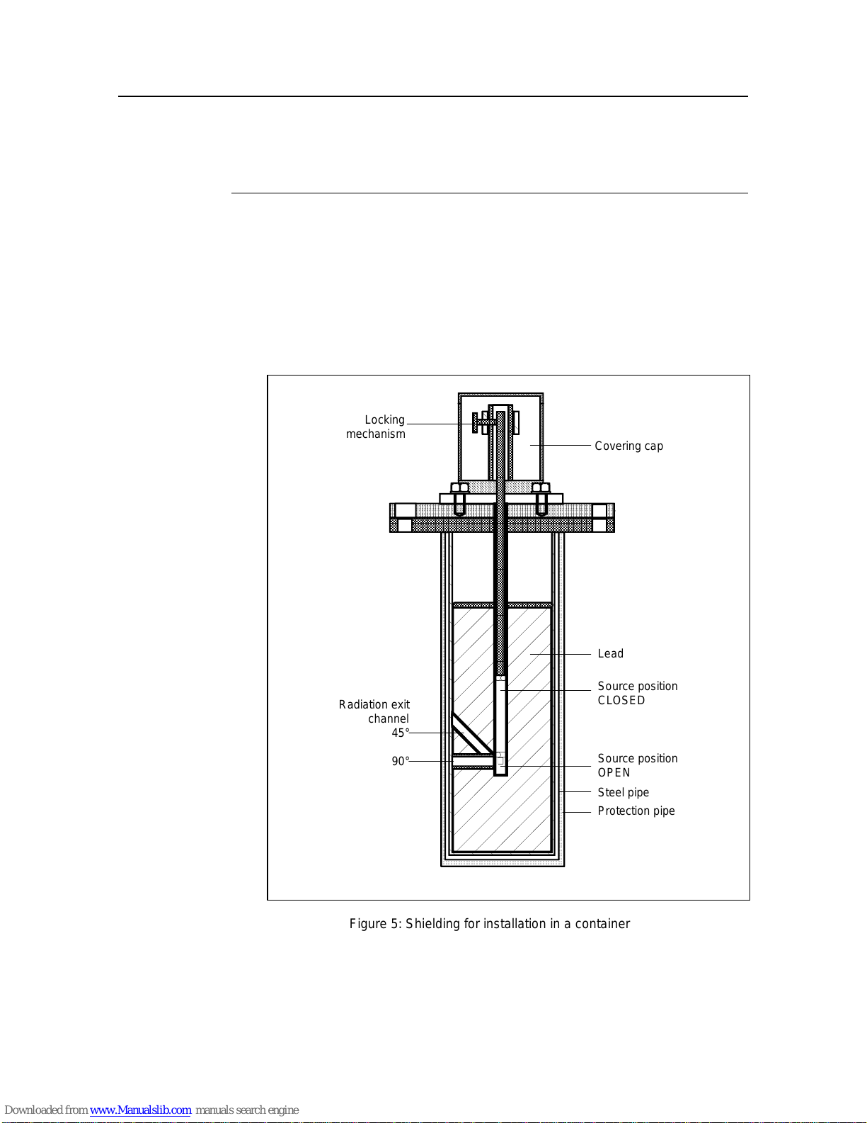
2.4.1.2 Shieldings for Installation in a Container
Shieldings with manually operated lock
The shielding consists of a lead-filled steel pipe, with a guide tube for the radio-
active source installed in the center. The radiation exit channel is located in an
angle of 90° or 45° to the longitudinal axis.
After taking off the covering cap which is secured by a lock you may open the
knurled screw and, using the stay bar, move the radioactive source forward
(OPEN) or back (CLOSED).
Locking
mechanism Covering cap
Lead
Source position
CLOSED
Steel pipe
Protection pipe
Source position
OPEN
Radiation exit
channel
45°
90°
Figure 5: Shielding for installation in a container

Density Meter LB 444 SECTION 2. SYSTEM DESCRIPTION
10
Shutter switches signal the position of the sources.
Two versions are available:
a) Version for use in areas not endangered of explosion:
2 Reed contacts max. 250 V, 40 VA
1 x for OPEN, 1 x for CLOSED.
b) Version for use in the areas endangered of explosion:
1 proximity switch for position CLOSED.
It has to be connected to an inherently safe power supply.
Closed
Open
Switch flag
Cover cap
Connection for
pressurized air electr. signal
OPEN/CLOSED
Proximity
switch
Figure 6: Shutter switch for ex-protected area
See the drawings that are part of the documentation for detailed information on
the construction and function of the shielding type used.

Density Meter LB 444 SECTION 2. SYSTEM DESCRIPTION
11
Detector
Scintillation counters are used as detectors, since only these detector systems
provide the required high sensitivity to Gamma radiation and the radiation field
does not limit their service life.
The detector comprises
•a sodium iodide crystal doped with Thallium
•a photomultiplier
•an electronics unit.
The built-in microprocessor tracks the configuration, counts the pulse rates,
controls the high voltage, measures the temperature of the probe and an exter-
nal Pt 100, transfers data and performs calibration and control functions.
+
−
AMPLIFIERRADIATION
LIGHT FLASH
SCINTILLATOR DYNODES
PHOTO CATHODE
.
.
.
Figure 7: Scintillation counter
The scintillator converts the incidence of Gamma into light flashes.
The flashes of light are converted into electrical signals in a photomultiplier,
which is optically coupled, to the detector. To achieve a very high accuracy and
a high long-term stability, the integrated processor automatically adjusts the op-
timum operating point of the photomultiplier, monitors the limit values, and
stores all detector-specific data. Power is supplied via 2-wire technique; all
measured data and information is transmitted between detector and the evalua-
tion unit at the same time.
The detector probe is mounted in a sturdy stainless steel housing which pro-
tects the instrument against normal environmental stress.
To ensure reliable operation and a long service life, the detector probe
must not be subject to heavy mechanical stress or vibrations.
Cooling must be provided for ambient temperatures above 50°C. (see sec-
tion 3.3 Installation of Water Cooling).
For more information see: Technical Information LB 444.

Density Meter LB 444 SECTION 2. SYSTEM DESCRIPTION
12
Evaluation Unit LB 444
2.4.1.3 General Description
The evaluation electronics is designed as a 19" module in the format 3 HE, 21
TE. It includes the microprocessor-controlled evaluation electronics and the
power supply. A 32-bit microprocessor with menu-structured software specially
designed for density measurements is used for signal processing.
The six foil keys on the front panel are used to operate the instrument.
•Three keys work as soft-keys which allow user-guided definition of all in-
strument settings and input of the required parameters.
•Three more keys serve as function keys.
The illuminated display field on the front panel shows the relevant instrument
function on four lines. The front panel also includes an RS 232 interface.
enter
clear run
LCD display
BERTHOLD
Softkeys
Funktion keys
..
..
..
..
..
..
EG&G Berthold
LB 444 V 1.00
Density - Meter
more
Figure 8: Front Panel LB 444
The terminal strip on the instrument rear panel includes all terminals for power
for the detector and for the analog and digital output signals. The current output
is isolated and the built-in relays for max.-min.-indication and for error messages
include an isolated contact.
The system automatically corrects for the decrease of source activity with age.
System malfunctions are signaled by error messages.
The calibration data is stored in a FLASH memory and saved during loss of
power.

Density Meter LB 444 SECTION 2. SYSTEM DESCRIPTION
13
2.4.1.4 Display
The illuminated display field of the instrument comprises 4 lines; the first three
lines show the menu titles, the currently selected parameters or the current
measurement value. The bottom line shows the current function of the softkey
button located below or, when a measurement is running, the status “run“.
2.4.1.5 Keypad Function
The Density Meter is operated via the softkeys and function keys de-
scribed below; which select the desired operating level within a menu
structure in order to select a function or enter parameters. The menu
guidance is illustrated in the quick overview of the menu structure
(see next page) and from tables (see Appendix).
Softkeys
Softkeys are used to select different menu groups and operating lev-
els within the menu structure. Depending on the current position in
the menu structure, functions are assigned to these keys, as shown
on the display above the respective key.
<sk1>and
<sk2> switch to the indicated menu (Figure 9 a).
<more> switch to the next menu group.
<done> shows the end of the menu and takes you back to the
menu group.
<^^^> text: scrolls through the various selection options (Figure
9 b)
numerical values: increments the number marked by the
cursor by 1.
<!!!
!!!!!!
!!!> moves the cursor to the left and at the end of the input
field again to the start position (Figure 9 c).
<+> and
<-> scrolls forward / back in the submenus (Figure 9 d).
Figure 9: Softkeys functions
Function Keys
<enter> accepts the entry and moves the cursor to the next input
field or toggles between two input fields.
<clear> clears the numerical value.
Figure 10: Live display
sk1: general
sk2: operating
sk1 sk2 more
a)
Product select
[extern/intern]
^^^ done
intern
b)
time constant
more
value: 20.000
←
←←
←←
←←
←←
←←
←
∧∧∧
∧∧∧∧∧∧
∧∧∧
c)
HV (500): 112 cps
+ - exit
HV (560): 116 cps
HV (620): 122 cps
d)
LB 444
Density = 1.5g/cm³
+ - RUN more
<run> starts or ends a measurement or leads directly back to
the display and at the start of a measurement automati-
cally changes to the measurement value display.

Density Meter LB 444 SECTION 2. SYSTEM DESCRIPTION
14
2.4.1.6 Menu Structure (Flow Chart)
The flow chart below shows in a simplified way the menu structure for parameter
input and operation. With <more> you select the various menu groups and from
there you get to the respective menu with <sk1> or <sk2>. Within the menu you
get to the individual windows with <more> and at the end of the menu you get
back to the menu group with <done>. For a complete overview of the menu
structure see the appendix to this manual.
↓
↓
↓
Parameter
Isotope
Time Constant
Rapid Switch-Over
Rad. Interference
Maximum Rate
Minimum Rate
Product Data
Product Selection
Curr. output Limits
Current outp. error
Relay 2 + 3 Setup
Solids density
↓↓
sk2
sk1 more
Productselect
↓sk2
sk1 more
Service menu ↓
Pt100 Adj./Plateau
Test calculation
HV Setting/Status
Adj. Current Out
↓↓
↓
sk2
Calibrate
Countrate
Massflow display
Density display
Integr. M.
Flow
sk1 more
Product Selection
Calculate
Cal. Mode
Resuls
Data Input
↓↓
Oper. Mode
Mass flow
Config Instrument
Density / TC
Password
Date & Time
System/ Version
Language
General Data
sk2sk1 more
Error Mode
Print Parameter
Factory Setting
Rad./Backscatter
Interfaces
Liquid density
HV Detector
Live Display
Unit
Range Input
Flow
Counter Interval
Massflow

Density Meter LB 444 SECTION 2. SYSTEM DESCRIPTION
15
2.5 Software Functions and System Configuration
The factory settings are listed in the Configuration Checklist in the Appendix.
Enter the final operating settings in this list. Please remember that the entry in all
operating levels is made with the <^^^> key and the new value is accepted with
<enter>.
General Data
Password: One may enter a number comprising up to 6 digits. Upon confirmation with <en-
ter>, the system is protected against unauthorized manipulation of the parame-
ters. All parameters can still be viewed, however. The password protection is
canceled when you enter the correct numerical value and confirm your entry
with <enter>.
Date: Enter the current date in the format TT.MM.YY. The correct date is important for
automatic correction of the activity decay of the source.
Time: Enter the current time in the format HH.MM. Time deviations have hardly any
effect on the correction of the activity decay; checking the time can help to check
the instrument function.
System/Version:
Display of instrument type and software program version.
Language: You can choose German, English or French as dialog language by pressing the
<^^^> key.
Print Parameter:
A printer with serial interface can be connected on the front panel. All parame-
ters can be printed for documentation. The printout in the appendix shows an
example. A PC may also be connected and the data transferred to the computer
and processed there using a terminal program.
Factory Setting:
All parameters can be reset to the factory setting with <sk1>. However, a meas-
urement with this data only is not possible.
The current calibration data is lost when the instrument is reset!
Table of contents
Other Berthold Measuring Instrument manuals

Berthold
Berthold BTwave LB 571-02 User manual

Berthold
Berthold Duo Xpert LB 478 MPLM User manual

Berthold
Berthold DUO XPERT LB 470RID User manual

Berthold
Berthold InlineSENS Duo Series User manual

Berthold
Berthold DuoXpert LB 476 Level+ User manual

Berthold
Berthold MicroPolar LB 566 User manual

Berthold
Berthold LB 134 User manual

Berthold
Berthold LB 444 K-40 User manual

Berthold
Berthold Uni-Probe LB 491 User manual

Berthold
Berthold castxpert LB 452 User manual


