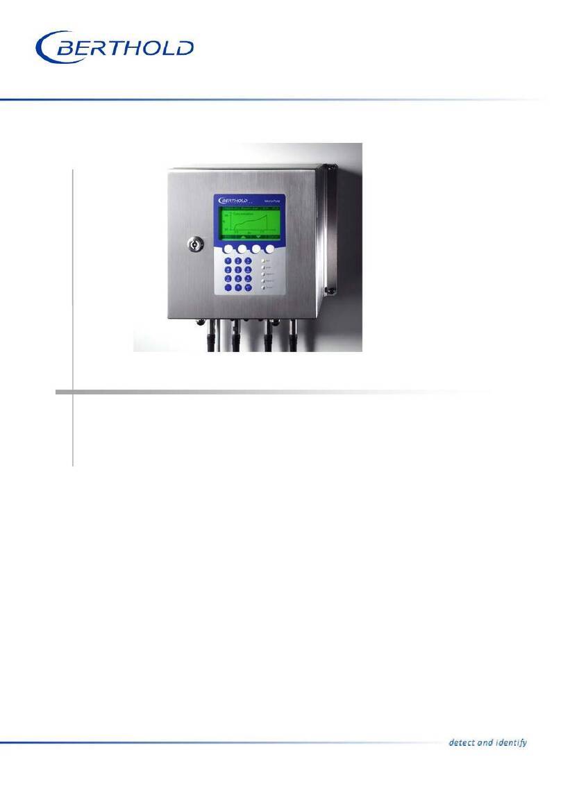
Berthold LB 442 User manual

Radiometric
Bulk Flow Meter
LB 442
Id. No. 32815BA2
Rev. Nr.: 02 10.10.2001


Table of Contents
1
Table of Contents
Page
Section 1 Introduction 5
1.1 Safety Summary 5
1.2 Overview 6
Section 2 System Description 7
2.1 Use and Function of the Bulk Flow Meter 7
2.2 The Principle of Measurement 8
2.3 Measuring Configuration 9
2.3.1 Configuration on Conveyor Belt 10
2.3.2 Configuration for Free Fall Measurement 11
2.4 Instrument Description 12
2.4.1 Rod Source 12
2.4.2 Measuring Frame for Conveyor Systems 13
2.4.3 Two-Detector Operation 17
2.4.4 Measuring Device for Free Fall Measurement 18
2.4.5 Measuring Frame for Rod Detector 19
2.4.6 Rod Source with Rod Detector 20
2.4.7 Point Source Shielding 20
2.4.8 Detector 20
2.4.9 Tachometer 22
Section 3 Installation 23
3.1 General Safety Precautions 23
3.2 Installation of the Measuring Device 24
3.2.1 Installation on Conveyor Belts 24
3.2.2 Measuring Frames on Screw Conveyors 27
3.2.3 Measuring Frames on Chain Conveyors 28
3.2.4 Installation for Free Fall Measurement 28
3.3 Installation of Water Cooling 30
3.4 Tachometer Installation (Option) 32
3.4.1 Conveyor Belt Installation 32
3.4.2 Chain and Screw Conveyor Installation 32
3.5 Installation of Evaluation Unit 32
Section 4 Electrical Connections 33
4.1 Detector 33
4.2 Evaluation Unit LB 442 34
SECTION 5 Getting Started 38
5.1 Quick Installation Overview 38
5.2 Getting Started 39
5.2.1 Opening the Radiation Exit Channel 39
5.2.2 Re-adjusting the Detector 40
5.2.3 Basic Settings 41
5.2.4 Calibration 43
Section 6 Evaluation Unit LB 442 45
6.1 General Description 45
6.1.1 Menu Structure (Flow Chart) 48
6.2 Software Functions and System Configuration 49
6.2.1 Slave Menu Functions 66

Table of Contents
2
Section 7 Calibration 68
7.1 Background 68
7.2 Tare Measurement 68
7.2.1 General Information 68
7.2.2 Tare Compensation 70
7.3 Calibration 71
7.3.1 General Information 71
7.3.2 External Product Selection 71
7.3.3 Preparation for Calibration Weighing 72
7.3.4 Standard Calibration Procedure Step-by-Step 74
Section 8 Checking the Calibration 76
8.1 General Information 76
8.1.1 Correction of Calibration 76
8.1.2 Operating Instructions for Calibration 76
8.2 Correction of Display Value 77
8.2.1 Offset 77
8.2.2 Factor 77
Section 9 Operation of the Radiometric Bulk Flow Meter 78
9.1 Live Display 78
9.2 Regular Operation 78
9.2.1 Results 78
9.2.2 Zero Point Correction through Tare Measurements 79
9.2.3 Batch Operation 80
9.3 Operation with Different Materials 80
9.4 Evaluation Unit as Dry Weight Computer 81
9.5 Starting/Stopping Operation of the System 81
9.6 Error Messages 82
9.6.1 Resetting Error Messages 82
9.6.2 Error Messages during Operation 82
9.6.3 Error Messages during Calibration 83
9.6.4 Error Messages during Measurement 83
Section 10 Technical Data 84
10.1 Evaluation Unit LB 442 84
10.2 Detector 86
10.3 Wall Housing LB4460 88
Section 11 Service Instructions 89
11.1 General Safety Precautions 89
11.2 Trouble Shooting 89
11.3 Shielding and Source 90
11.4 Evaluation Unit LB 442 92
11.4.1 Battery 92
11.4.2 Error Code Listing 93
11.4.3 Error Code Listing with Signal Output 94
11.4.4 Service Functions 95
11.5 Scintillation Detector 98
11.5.1 Working Principle 98
11.5.2 Malfunctions 99
11.5.3 Checking the Crystal-Multiplier Assembly 101
11.5.4 Replacing the Crystal-Multiplier Assembly 103
11.6 Replacing the Evaluation Unit 103
Section 12 Radiation Protection 104
12.1 Basics and Guidelines 104

Table of Contents
3
12.2 Safety Instructions 107
12.2.1 Shielding Installation 107
12.2.2 Rod Source Replacement 108
12.3 Radiation Dose Calculations 112
12.3.1 Exposure when Installing the Shielding 113
12.3.2 Exposure when Replacing Rod Sources 113
12.4 Emergency Instructions 114
Section 13 Appendix 115
13.1 Certificates 115
13.1.1 ATEX Certificate for Evaluation Unit 115
13.1.2 ATEX Certificate for Detector 120
13.1.3 ATEX Certificate for Wall Housing 124
13.1.4 Declaration of Conformance 127
13.2 Parameter Protocol (Example printout) 128
13.3 Tachometer Installation 130
13.3.1 Tachometer 132
13.4 Mechanical Drawings 133
13.4.1 Measuring Frame with Rod Source and Point Detector 133
13.4.2 Measuring Frame with Rod Source and 2 Point Detectors 134
13.4.3 Measuring Frame Divided 135
13.4.4 Free Fall Measurement 136
13.4.5 Point Detector 137
13.4.6 Measuring Frame for Rod Detectors 138
13.4.7 Holding Device for Point Source Shielding 139
13.4.8 Rod Detector 140
13.4.9 Mounting Brackets for Rod Detectors 141
13.4.10 Point Source Shielding 142
13.4.11 Evaluation Unit 143
13.5 Wiring Diagram 144
13.5.1 Wall Housing 144
13.5.2 Wall Housing with Two-Detector System 145
13.5.3 19" Frame 146
13.6 Menu Structure 147
13.6.1 Parameter Menu 147
13.6.2 Calibrations and Measurement Menu 148
13.6.3 Slave Menu 149
13.6.4 Service Menu 150
13.7 Configuration List 151
13.7.1 Calibration Data Table 153
13.8 Index 154

Revision History
4
Revision History
No. Date Comments
0 27.04.1998
1 22.02.2000 FSK revision, detector code, error listing revised, wirin
g
dia
g
rams
and mechanical drawings revised, menu structure added.
2 10.10.2001 Rev2 is based on software version 2.10
The following modifications were added:
ATEX and Master Slave expansion added, functions, menus and
parameter table update, EG&G removed, wiring diagrams revised,
bulk flow measurement with rod detector added, mechanical
drawings completed, calibration explained in more detail.

Section 1 Introduction
5
Section 1 Introduction
1.1 Safety Summary
General Warnings
Environmental Conditions
All system components require non-corrosive environmental conditions during
transportation, storage and commissioning.
Electrical Shock Hazard
Disconnect power to ensure that contact with energized part is avoided during in-
stallation and servicing.
Special Precautions
The measuring system electronics contains components that are highly sensitive
to electrostatic discharge!
Specific Warnings
Never change the installation or the parameter settings without a full knowledge
of the relevant part of this manual, the connected controller and the process, if it
is controlled by this measuring device.
Specific Cautions
This measuring device utilizes radioactive sources. Strict adherence must be
made with regard to the rules of Radiation Protection in this manual and the local
regulations pertaining to the use of radioactive sources.
Installation, dismantling, relocation, maintenance, testing involving the radioac-
tive source, or its shielding shall be performed by persons specifically licensed.
Radioactive sources, which are not in use have to be stored at a save place which
is tamperproof.
Ex Protection
All ex/protected resources may be repaired and serviced only by personnel
licensed by the manufacturer.

1.2 Overview
6
1.2 Overview
The Radiometric Bulk Flow Meter LB 442 is designed for non-
contacting measurements of material on conveyor belts, screw
conveyors or chain belt conveyors as well as free fall installations.
The measuring system LB 442 utilizes the radiometric measure-
ment method, i.e. the attenuation of Gamma radiation passing
through the product being measured.
In order to obtain an optimum measuring effect at minimum
source activity, the ideal measuring geometry is calculated for the
respective measuring location and the source is designed accord-
ingly.
Radiometric measuring systems utilize radioactive substances
that are manufactured in compliance with official regulations and
which are protected by suitable shieldings. When handled prop-
erly, any hazards to personnel due to built-in radioactive
substances can be ruled out. As prescribed by law, these
measuring facilities may be operated only by specifically li-
censed persons with sufficient expertise and training.
The hardware and software of the LB 442 system makes it easy to
adapt the system to rather different measuring geometries and
measuring tasks. Therefore, the settings and parameters of the
measuring instrument have to be defined with care for the respec-
tive measuring task when taking the system into operation. The
system should be taken into operation and settings changed only
by persons who know how to work with the instrument. Therefore,
all users should read these operating instructions carefully. We
recommend documenting all settings in a setup protocol (see Ap-
pendix).
This instruction manual describes several possible measuring con-
figurations and instrument versions. The best system configuration
is selected for each measuring task during the planning stage.
Therefore, the respective project documentation has to be ob-
served and taken into account.
Before starting any work, please read this operating manual
carefully!

Section 2 System Description
7
Section 2 System Description
2.1 Use and Function of the Bulk Flow Meter
The radiometric Bulk Flow Meter LB 442 can be used to determine
the load
□on conveyor belts
□on screw conveyors
□on chain conveyors
□on troughed chain conveyors
□during free fall.
The measurement can be carried out directly on the conveyor sys-
tem or – in case of free fall measurement - at the discharge sta-
tion.
Special instrument configurations and calculations allow adapting
the radiometric bulk flow measurement to the local situation and
the conditions of the product being measured:
a) Instrument configuration (Operating modes)
□Measurement at constant belt speed
□Measurement with tachometer
□Measurement with moisture compensation
b)Measured value
□Conveyed material
□Load
c) Selection of measurement mode
□Continuous measurement
□Discontinuous measurement
- Batch operation via keyboard (press <run> button)
- Batch operation via digital input
d)Result Output
□Live on LCD display for load and quantity
□Current output 0/4 - 20m/A for load
□Pulse output for load
□Minute printout
□Shift printout

2.2 The Principle of Measurement
8
2.2 The Principle of Measurement
The principle of determining mass with a radiometric Bulk Flow Me-
ter can be compared to that of X-raying material lying on the con-
veyor. To generate the radiation, which is physically identical to
that of X-ray radiation, radioactive material is used which is easy
to handle and whose energy is dependent on the load on the con-
veyor. The radiation is absorbed by the product on the belt and the
attenuated radiation is picked up by a detector and evaluated by
the microprocessor unit
The attenuation occurring during maximum conveyor throughput
determines the choice of source. Any material between source and
detector reduces the intensity to be measured at the detector.
The radiometric measurement utilizes the physical law of the at-
tenuation of gamma radiation passing through the product being
measured. The resulting measurement effect is the ratio I/I0 be-
tween the unattenuated radiation I0 and the radiation I which is
attenuated by the product being measured. The remaining radia-
tion picked up by the detector (scintillation counter) stands for the
mass of the product being measured. Figure 1 illustrates the prin-
ciple of measurement. The radiation is attenuated according to the
following formula:
I = Io* e - µ' * roh * d
I = Radiation picked up with load
I0= Unattenuated radiation without load
µ= Absorption coefficient) in cm2/g
roh = bulk density of the material on the conveyor in g/cm3
d = height of absorbing material in cm
Detector
Figure 1: Principle of measurement
Source
ρd

Section 2 System Description
9
The minus sign signifies that the intensity decreases as the load
increases. Apart from the constant factor, the initial intensity I0is
only affected by the product "roh xd", where "roh" is the density
of the conveyed material, i.e. the bulk density, and d the path cov-
ered by the radiation in the material.
If we multiply "roh x d", we get the mass per unit of area. This
variable is known as the weight per area and is assigned the unit
g/cm2.
The intensity of the radiation is therefore dependent upon
the height and bulk density of the material. The product of
height and bulk density is the weight per area!
If the mass per unit of area is now multiplied by the material
width, the result is the mass over 1 m of the conveyor; multiplica-
tion by the speed results in the desired mass per time unit, e.g.
tons per hour.
Contamination of the product being measured or the pipeline wall
by gamma radiation is not possible at all.
2.3 Measuring Configuration
To be able to cover a certain measuring range continuously, a
measuring configuration must be realized where the dimensions of
source and detector form an optimum geometry covering a meas-
uring field of equal size. The different options that are available
will be described below.
Which of these arrangements is chosen is dependent upon the
conveyor facility. Moreover, construction factors and customer-
specific requirements may have an effect on the instrument selec-
tion. The respective selections are made during the planning stage
and have to be taken into account later during assembly and
commissioning.
A measuring system for the radiometric bulk flow measurement
typically comprises the following components:
a) Radioactive rod source inside a:
b) Shielding container with holding device for detector:
- Measuring frame with shielding container (conveyor belt,
etc.) or
- Holding device with shielding for free fall measurement
c) Detector
d) Evaluation unit LB 442
e) Two-wire cable
f) Tachometer (Option)
g) Cooling jacket for detector (option)

2.3 Measuring Configuration
10
The power supply for the detector and the measuring signal
(pulses) are transmitted via the two-wire cable connected between
detector and evaluation unit.
Different configurations and mounting devices may be required,
depending on the conveyor system and the measuring tasks.
2.3.1 Configuration on Conveyor Belt
Figure 2 shows a basic setup on a conveyor belt. Basically, this
setup is the same for screw and chain conveyor types.
Measuring
Frame Szintillation
Counter
Produc
t
Conve
y
or Bel
t
Rod Source
Figure 2: Measuring system mounted on conveyor belt
The foot of the measuring frame contains the shielding container
with the rod source which is typically installed below the conveyor
belt.
The detector is mounted on the crossbeam of the measuring
frame, so that the detector opening is located directly above the
radiation exit channel of the shielding.
Detector and evaluation unit are connected via two-wire cable.
The optional tachometer is connected to the evaluation via 3-wire
cable.
See 13.5 Wiring Diagram in the Appendix on page 144.

Section 2 System Description
11
2.3.2 Configuration for Free Fall Measurement
Using a clamping device, the radiation source (rod source) in its
shielding is installed on one side of the fall-pipe and the detector
on the opposite side. The radiation entrance window is located on
the front side of the detector.
with screw thread and protection plate
Shielding Bolt bar Shielding plate Detector
Figure 3: Top view of configuration for free measurement

2.4 Instrument Description
12
2.4 Instrument Description
2.4.1 Rod Source
Radioactive sources for industrial applications are always „encap-
sulated radioactive substances“ which are tightly welded into a
sturdy stainless steel capsule, so that the radioactive substance
cannot leak out. Contamination is therefore ruled out. Moreover,
any activation of the product being measured by the sources used
is not possible for physical reasons.
The following rod-shaped Gamma sources can be used for these
measuring configurations: 241Am, 60Co, 137Cs, 85Kr.
The following isotopes are primarily used for the radiometric bulk
flow measurement:
a) 60Co has a relatively high energy of 1.17 and 1.33 MeV, respec-
tively. It is used for very high loads. Its half-life period is 5.27
years. *
b) 137Cs is the isotope most frequently used for radiometric bulk
flow measurement. Its energy of 0.660 MeV is sufficient to irra-
diate common belt loads. Due to the lower energy, the measur-
ing effect is better than with Co-60. Also, the shielding costs for
a Cs-137 source are lower than for a Co-60 source. The half-life
period of Cs-137 is approx. 30 years.*
The rod-shaped Cs-137 source is assembled from several
pieces.
c) 241Am has a very low energy (60 keV) which is much easier to
shield. Therefore, a much smaller lead shielding suffices. 241Am
is rarely used due to its minor radiation energy, mainly for ma-
terials such as tobacco and washing powder or for very low belt
loads.
Caution: Due to its low energy, it has to be borne in mind that
the attenuation of the radiation is dependent not only on the
bulk weight and height, but also on the atomic number. This
means that the result can be distorted when the chemical com-
position changes. How much has to be determined on an indi-
vidual basis.
* According to NBS, half-life is defined as: Time for the activity of
any particular radioisotope to be reduced to half its initial value.
Please note the Radiation Protection Guidelines in the
Service Instructions on page 89!

Section 2 System Description
13
2.4.2 Measuring Frame for Conveyor Systems
The measuring frame is a special construction for conveyor belts,
chain and screw conveyors; its foot includes the lead shielding for
the rod source. The detector is mounted to the crossbeam using
the supplied installation set. The product being measured flows be-
tween source and detector, with the source generally mounted be-
low the stream of material to be conveyed.
Another frame installation is required for hot products if a heat
guiding plate or a water cooling protecting the detector cannot be
installed. For this application, the detector is mounted below and
the shielding with the source above the stream of material to be
conveyed.
There are two different types of measuring frames, the Co-
balt/Cesium version and the Americium version.
Co or Cs version: the detector is mounted horizontally using two
holding shackles below the crossbeam. Use the installation set en-
closed with the instrument for installation.
Americium measuring frame: the detector is installed vertically
using the clamping device attached in the center part.
Detector Detector holder
a
c
b
d
e
Figure 4: Measuring frame

2.4 Instrument Description
14
Shielding
The effectiveness of the shielding and the smooth operation
of the lock must be checked every six months!
Measuring frames for Co and Cs sources are equipped with a
lead-filled steel pipe as shielding, the outer diameter being 105
mm, and a radiation exit channel having a width of 8 mm. When
the exit channel is closed, the radiation hits the steel shielding.
The open radiation exit channel is exactly aligned with the scintilla-
tion counter that is installed on the opposite side.
Measuring frames for Americium sources do not require such
strict shielding precautions, since the radiation emitted by Ameri-
cium is much easier to shield off.
Radiation exit channel
40 mm
Changing Distance from Shielding with rod source Opening/
the rod bottom 40 mm closing the
source radiation exit
channel
Figure 5: Shielding in foot of measuring frame
On one side of the shielding (see Figure 5) there is the opening for
changing the rod source which is secured by a special lock and a
padlock.

Section 2 System Description
15
On the other side of the shielding is a device for opening and clos-
ing the radiation exit channel. To open or close the radiation exit
channel, turn the lever to the respective position (see Figure
6(a)).
The red arrow indicates the position of the radiation exit channel.
If it points up, the useful beam is opened toward the detector. If
this arrow points horizontally, the radiation exit channel of the
shielding is closed.
(e) OPEN position (c) Lock
(d) Threaded - (b) Hexagon head cap screw
bore hole for arresting the shielding
Figure 6: Shielding (side view) in foot of measuring frame
Open radiation exit channel only for measurement opera-
tion!
Do not stay or reach into the radiation path!
With the radiation exit channel open, the hexagon head cap
screw must be tightened firmly!
Closing the radiation exit channel (see Figure 6)
1. Unscrew hexagon head cap screw (b) on metal plate (a).
2. Insert key in lock (c).
3. Push in lock and turn key to open the lock. Now you can move
the radiation exit channel by turning the lever (a).
4. Turn metal plate until the bore hole on the metal plate sits over
the next threaded bore hole (d). The red arrow (e) now points
horizontally.
5. Turn in hexagon head cap screw.
6. Turn key in lock and pull it out.
(a) Lever
for turning
the shielding

2.4 Instrument Description
16
Opening the radiation exit channel (see Figure 6)
1. Unscrew hexagon head cap screw (b) at lever (a).
2. Insert key in lock (c).
3. Push in lock and turn key to open the lock. Now you can move
the radiation exit channel by turning the lever (a).
4. Turn lever until the arrow points straight up and the bore hole
on the metal plate sits over the respective threaded bore hole.
5. Turn in hexagon head cap screw and tighten it firmly (!). The
source must sit absolutely tight, so that possible vibrations of
the conveyor system cannot move the source in the shielding.
6. Turn key in lock and pull it out.
Figure 7: Measuring frame - side view
Detector
Connection to
evaluation unit
Shielding

Section 2 System Description
17
2.4.3 Two-Detector Operation
Two detectors have to be used on wide troughed chain conveyor
systems, e.g. for measurements on recycling paper. The second
detector has to be connected to a special slave evaluation unit. The
evaluation unit of the first detector works as a master. The count
rate and error messages of the slave system are transmitted to the
master via the RS 485 interface. See also the wiring diagrams on
pages 145 and 146.
Besides transmitting the count rates and possible error messages,
the slave has no further function. The master takes over control ofr
the entire measurement. Since both detectors are fully compatible,
it is irrelevant which of the detectors is connected to the slave or
to the master.
Figure 8: Master-slave wiring
With a 2-detector system, only the detector code has to be entered
at the slave.
See also Detector list on page 52 and Slave Menu on page 149.
Parameter setting and calibration are carried out on the Master. In
addition, the following parameter has to be set in the Master
menu, item Interface:
RS485: Slave
Number of detectors: 2

2.4 Instrument Description
18
The Slave address in the Master can remain on the standard value
1, provided the standard address in the Slave has not been
changed.
See also Interfaces on page 65.
2.4.4 Measuring Device for Free Fall Measurement
The measuring frame must be installed close to the discharge sta-
tion. This reduces the theoretical rate of fall at the measuring
point, for according to the law of gravitation the rate of fall rises as
the distance increases. With rising rate of fall the weight per area
and thus the accuracy of the measurement decreases.
When using the free fall bulk flow meter on pipes, a measuring de-
vice as depicted in Figure 9 is used. The measuring device can
simply be mounted onto existing fall-pipes. It consists of a shield-
ing with rod source and a variably adjustable holding plate for the
detector. Depending on the diameter of the fall-pipe, the holding
plate can be adjusted via the 4 threaded rods.
Am-241 shielding
Shielding plate preventing access to the radiation path
a = b = Variable adjustment
c = ca. 420 mm d = Pipe diameter between 89.9 and 304 mm
Figure 9: Free fall bulk flow measuring device (top view)
On fall chutes, measuring frame and rod source holder are used as
depicted in Figure 7.
ab
c
d
Detector
Holding plate
Threaded rod
Fall-pipe
Table of contents
Other Berthold Measuring Instrument manuals

Berthold
Berthold MicroPolar LB 566 User manual

Berthold
Berthold BTwave LB 571-02 User manual

Berthold
Berthold LB 444 User manual

Berthold
Berthold DuoXpert LB 476 Level+ User manual

Berthold
Berthold Duo Xpert LB 478 MPLM User manual

Berthold
Berthold LB 9510 User manual
Berthold
Berthold Duo Series User manual
Berthold
Berthold castxpert LB 452 User manual
Berthold
Berthold Uni-Probe LB 491 User manual
Berthold
Berthold Duo XPERT LB 470 Level User manual
