Berthold MicroPolar Brix ++ LB 565 User manual
Concentration Meters
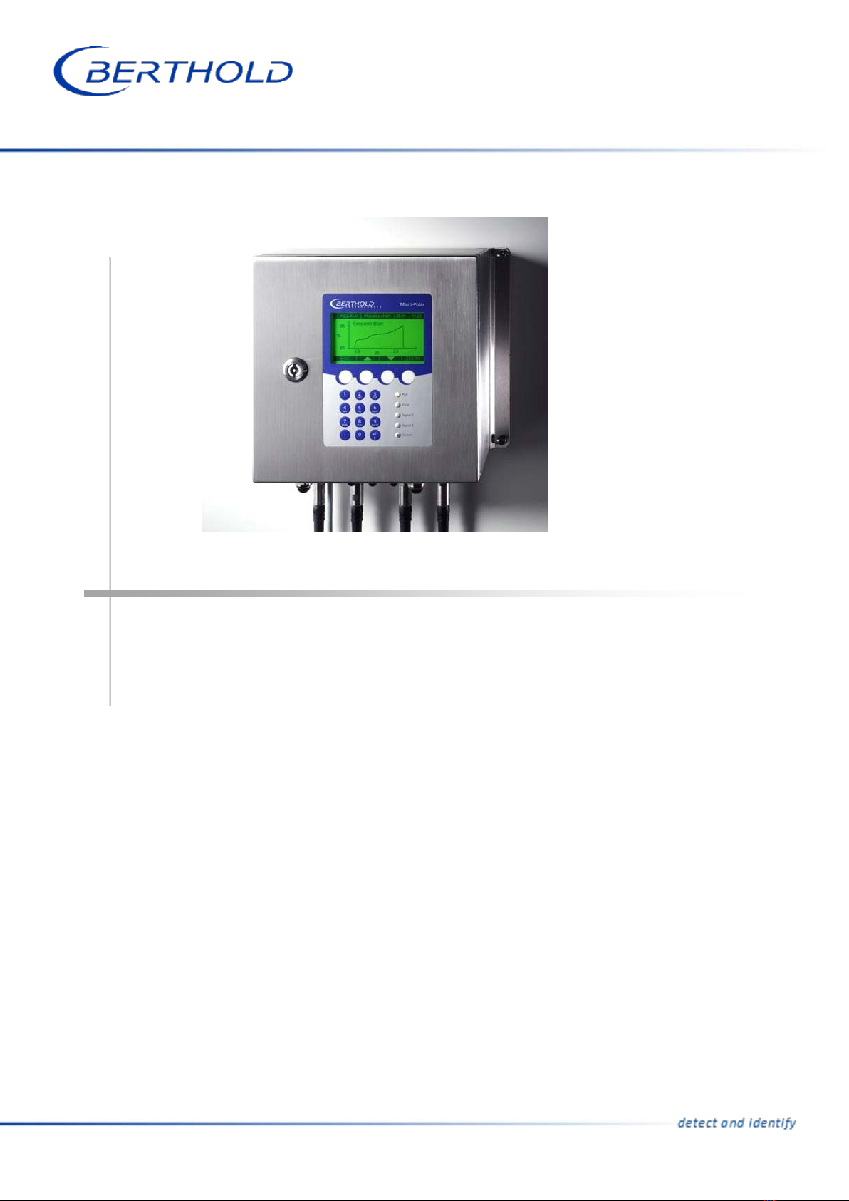
MicroPolar Brix (++)
LB 565
User’s Guide
Hardware Manual
39531BA2
Rev. Nr.: 08, 07/2023


MicroPolar Brix (++) LB 565
The units supplied should not be repaired by anyone other than Berthold Technolo-
gies Service engineers or technicians by Berthold Technologies.
In case of operation trouble, please address to our central service department (ad-
dress see below).
The complete user’s guide consists of the hardware manual and the software manual.
The hardware manual comprises:
mechanical components
installation
electrical installation
technical data
electrical and mechanical drawings
The software manual comprises:
operation of the evaluation unit
parameter description
basic setup
calibration
error messages
The present manual is the hardware description.
Subject to change without prior notice.
BERTHOLD TECHNOLOGIES GmbH & Co. KG
Calmbacher Str. 22 ⋅D-75323 Bad Wildbad
Switchboard: Service:
Phone +49 7081 177 0 Phone +49 7081 177 111
Fax +49 7081 177 100 Fax +49 7081 177 339
www.Berthold.com

Table of Contents
MicroPolar Brix (++) LB 565 5
Table of Contents
Page
Chapter 1. Safety Summary 7
1.1 Symbols and Warnings 7
1.2 General Information 8
1.3 General Safety Instructions 9
Chapter 2. General Information 11
2.1 Use and Function 11
2.2 Frequency license 12
2.3 Intended Use 14
2.4 Explanation of Terms 15
Chapter 3. System Description 17
3.1 Principle of Measurement 17
3.2 Calculation of Measured Values 18
3.3 Temperature Compensation 19
3.4 Mechanical Components 20
3.4.1 Evaluation Units 21
3.4.2 Flow Cell 24
3.4.3 Container Probe 27
3.4.4 High-frequency Cable 31
3.5 Measurement Assembly on a Pipeline 33
3.6 Measurement Assembly on a Container 34
Chapter 4. Getting Started 35
4.1 Transport 35
4.2 Installation 35
4.2.1 FlowCell Installation 35
4.2.2 Container Probe Installation 37
4.2.3 Setting Up the Evaluation Unit 40
4.3 Connecting the Evaluation Unit 42
4.3.1 Connecting the HF Cable 42
4.3.2 Pin Configuration of the Connector Strip 45
4.3.3 Digital Outputs, Relay 49
Chapter 5. Service instructions 50
5.1 General Information 50
5.2 Wear Parts 51
5.3 Instrument Cleaning 53
5.4 Battery 54
5.5 Fuse Replacement 55
Chapter 6. Technical Data 57
6.1 Technical Data Evaluation Unit 57
6.2 Technical Data Sensors 60
6.3 Technical Data HF Cable 66
6.4 Format of Serial Data Output RS232 and RS485 68

Table of Contents
6 MicroPolar Brix (++) LB 565
Chapter 7. Certificates 69
7.1 EC Declaration of Conformity 69
7.2 Frequency License 72
Chapter 8. Technical Drawings 81
8.1 Dimensional Drawings of Evaluation Unit Housing 81
8.1.1 Evaluation Unit for MicroPolar Brix 81
8.1.2 Evaluation Unit for MicroPolar Brix ++ 82
8.2 Electrical Wiring Diagram 83
8.3 Dimensional Drawings Flow Cells 84
8.3.1 Type LB 5660-102-00X FlowCell DN 50 Flange, FDA 84
8.3.2 Type LB 5660-202-00X FlowCell DN 65 Flange, FDA 85
8.3.3 Type LB 5660-302-00X FlowCell DN 80 Flange, FDA 86
8.3.4 Type LB 5660-402-00X FlowCell DN 100 Flange, FDA 87
8.3.5 Type LB 5660-502-00X FlowCell DN 125 Flange, FDA 88
8.3.6 Type LB 5660-602-00X FlowCell DN 150 Flange, FDA 89
8.3.7 Type LB 5660-112-00X FlowCell DN 50 G-BS/M 90
8.3.8 Type LB 5660-212-00X FlowCell DN 65 G-BS/M 91
8.3.9 Type LB 5660-312-00X FlowCell DN 80 G-BS/M 92
8.3.10 Type LB 5660-412-00X FlowCell DN 100 G-BS/M 93
8.3.11 Type LB 5660-512-00X FlowCell DN 125 G-BS/M 94
8.3.12 Type LB 5660-612-00X FlowCell DN 150 G-BS/M 95
8.3.13 Type LB 5660-132-00X DN 50 96
8.3.14 Type LB 5660-232-00X DN 65 97
8.3.15 Type LB 5660-332-00X DN 80 98
8.3.16 Type LB 5660-432-00X DN 100 99
8.3.17 Type LB 5660-532-00X DN 125 100
8.3.18 Type LB 5660-632-00X DN 150 101
8.4 Dimensional Drawings Container Probes 102
8.4.1 Type LB 5650-01 102
8.4.2 Typ LB 5650-02 103
8.4.3 Type LB 5650-03 104
8.4.4 Type LB 5650-04 105
8.4.5 Type LB 5650-05 106
8.4.6 Type LB 5650-09 107
8.4.7 Installation Situation in Pipelines 108
8.5 Dimensional Drawings Container Flush Probes 109
8.5.1 Type LB 5651-01 109
8.5.2 Type LB 5651-02 110
8.5.3 Type LB 5651-03 111
8.5.4 Type LB 5651-04 112
8.5.5 Type LB 5651-05 113
8.5.6 Installation Situation in Pipelines 114
8.6 Installation Sheets for LB 5650 (Container Probe) 115
8.7 Installation Sheets for LB 5651 (Container Flush Probe) 117
Chapter 1. Safety Summary
MicroPolar Brix (++) LB 565 7
Chapter 1. Safety Summary
1.1 Symbols and Warnings
In this user manual, the term Berthold Technologies stands for the
company Berthold Technologies GmbH & Co.KG.
To rule out bodily injury and property damage, please keep in mind
the warning and safety instructions provided in this user manual.
They are identified by the following sings: DANGER, WARNING,
CAUTION or NOTICE.
Ind
icates imminent danger. If it cannot be avoided, death
or most severe personal injuries may be the consequence.
Indicates a possibly dangerous situation. The consequences
may be death or most severe personal injuries.
Indicates a possibly harmful
situation The consequences
may be minor or medium personal injuries.
Indicates a situation that may cause material damage
if the instructions are not followed.
IMPORTANT
Paragraphs with this symbol
provide important information on the
product and how to handle it.
TIP
Contains user tips and other useful information.

Chapter 1. Safety Summary
8 MicroPolar Brix (++) LB 565
Meaning of other symbols used in this documentation:
Warning: No intervention, do not alter anything
Requirement: Disconnect power
Requirement: Wear
safety boots
1.2 General Information
The most important safety measures a summarized in this user
manual. They supplement the corresponding regulations which must
be studied by the personnel in charge.
Please pay attention to:
the national safety and accident prevention regulations
the national assembly and installation directions
the generally recognized engineering rules
the information on transport, assembly, operation, service,
maintenance
the safety instructions and information in these operating in-
structions
the enclosed technical drawings and wiring diagrams
the characteristic values, limit values and the information on op-
erating and ambient conditions on the type labels and in the data
sheets
the signs on the devices
the country-specific licensing schemes

Chapter 1. Safety Summary
MicroPolar Brix (++) LB 565 9
1.3 General Safety Instructions
IMPORTANT
The equipment housings have IP 65 protection and are suitable for
outdoor applications. The units are factory tested and are delivered
in a condition that permits safe and reliable operation.
For outd
oor applications, the measuring systems must be protected
from direct sunlight and rain, for example by a suitable shelter.
IMPORTANT
Never change the installation and the parameter settings without a
full knowledge of these operating instructions, as
well as a full
knowledge of the behavior of the connected controller and the pos-
sible impact on the operating process to be controlled.
The systems may only be used in perfect technical condition and
only for the intended use!
Only let persons work with the systems who are mandated to do
this and are suitably qualified and adequately trained! Attachments
and changes to the systems which can affect the operational safety
and reliability are prohibited!
IMPORTANT
All
system components require non-
corrosive ambient conditions
during transport, storage and operation.
IMPORTANT
If liquid gets inside the instrument, cut off the power supply. The
equipment must be inspected and cleaned by an authorized service
center.
Ambient conditions

Chapter 1. Safety Summary
10 MicroPolar Brix (++) LB 565
Electrical hazards
Disconnect power to ensure that contact with live part is avoided
during installation and when servicing.
Disconnect the power supply before opening the instrument. Work
on open and live instruments is prohibited.
Caution! Potential hazards, material damage!
Device type:
LB 565
-12 MicroPolar Brix ++ (ID no. 51832-02)
When connecting the 24 V DC power supply, the + and
– poles
must be connected correctly. There is no reverse polarity protec-
tion!
Spare fuses must match
the rating specified by the device manu-
facturer. Short
-circuiting or manipulation is not permitted.
IMPORTANT
The LB 565 and all additional equipment must be connected to
mains via grounded connection.
IMPORTANT
The concentration meter LB 565 may
be installed, serviced and re-
paired only by qualified specialists.
Qualified specialists are persons who through professional training
have acquired sufficient skills in the respective field and who are
familiar with the relevant national industrial safety regulations, ac-
cident prevention directions, guidelines and accepted engineering
standards. They must be able to safely assess the results of their
work and they must be familiar with the contents of these user man-
ual.
Qualified persons

Chapter 2. General Information
MicroPolar Brix (++) LB 565 11
Chapter 2. General Information
2.1 Use and Function
The MicroPolar Brix LB 565 has been designed as a concentration
measuring system and may be used only for this purpose. If the
devices are used in a manner that are not described in this user
manual, the protection of the devices is compromised and the war-
ranty will be lost.
Berthold Technologies is liable and guarantees only that the devices
comply with its published specifications. The LB 565 may only be
installed in an undamaged, dry and clean condition. Alterations and
modifications to the system components are not permitted.
The LB 565 is not qualified as a "safety-related measurement".
The standards and guidelines the LB 565 complies with are itemized
in these device instructions in chapter 2.2 Frequency License and
chapter 7.1 EC Declaration of Conformity.
The FlowCell and the container probe has been classified as pressure
equipment acc. to art. 4 sect. 3 of guideline 2014/68/EU. Before
use, check whether the case of use corresponds to this classifica-
tion. In particular, the media compatibility of the components in
contact with the fluid must be checked.
The protection type of the LB 565 to IEC 60529 is max. IP 65.
The following use is inappropriate and has to be prevented:
The use under conditions other than the terms and conditions
stated by the manufacturer in their technical documentation,
data sheets, operating and installation manuals and other spec-
ifications.
The use after repair by persons not authorized by Berthold Tech-
nologies.
The use in a damaged or corroded state.
Operation with open or inadequately closed cover.
Operating with insufficient tightened adapters and cable glands.
Operation without the manufacturer’s recommended safety pre-
cautions.
Manipulating or bypassing existing safety facilities.
Authorized persons are those who, by law, are permitted to perform
the respective activity, or who have been approved by Berthold
Technologies for certain activities.
Conformity to
standards
Protection type
Warning against
misuse
Authorized persons
Pressure equipment
directive

Chapter 2. General Information
12 MicroPolar Brix (++) LB 565
2.2 Frequency license
This device complies with Part 15 of the FCC Rules and with In-
dustry Canada licence-exempt RSS standard(s).
Operation is subject to the following two conditions:
(1) this device may not cause harmful interference, and
(2) this device must accept any interference received, includ-
ing interference that may cause undesired operation.
Le présent appareil est conforme aux CNR d'Industrie Canada appli-
cables aux appareils radio exempts de licence.
L'exploitation est autorisée aux deux conditions suivantes:
(1) l'appareil ne doit pas produire de brouillage, et
(2) l'appareil doit accepter tout brouillage radioélectrique
subi, même si le brouillage est susceptible d'en compro-
mettre le fonctionnement.
FCC 1,
“IC 2“:
This equipment has been tested and found to comply with the limits
for a Class B digital device, pursuant to part 15 of the FCC Rules.
These limits are designed to provide reasonable protection against
harmful interference in a residential installation. This equipment
generates, uses and can radiate radio frequency energy and, if not
installed and used in accordance with the instructions, may cause
harmful interference to radio communications. However, there is no
guarantee that interference will not occur in a particular installation.
1FCC . Federal Communications Commission
2IC ... Industry Canada
FCC1and IC2
License labels
Chapter 2. General Information
MicroPolar Brix (++) LB 565 13
If this equipment does cause harmful interference to radio or tele-
vision reception, which can be determined by turning the equipment
off and on, the user is encouraged to try to correct the interference
by one or more of the following measures:
- Reorient or relocate the receiving antenna.
- Increase the separation between the equipment and re-
ceiver.
- Connect the equipment into an outlet on a circuit different
from that to which the receiver is connected.
- Consult the dealer or an experienced radio/TV technician
for help.
Changes or modifications made to this equipment not expressly ap-
proved by BERTHOLD TECHNOLOGIES may void the FCC au-thori-
zation to operate this equipment.
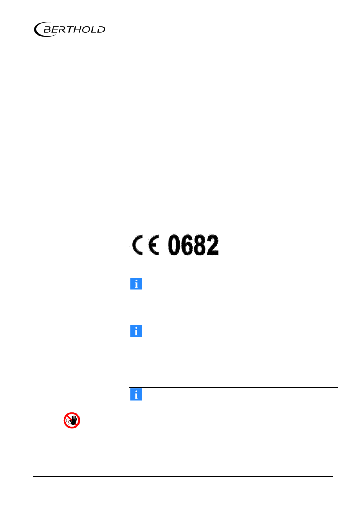
The MicroPolar Brix and MicroPolar Brix ++ comply with the R&TTE
Directive 1999/5/EC and thus meet all the requirements for this type
of high-frequency devices. As a mark of conformity in accordance
with the CE mark, the devices bear the no. 0682 of the certification
body. The certificate can be found in chapter 7.2 Frequency License.
IMPORTANT
The approvals and compliance are only applicable in combination
with the container probes and FlowCells.
IMPORTANT
The LB 565 has been manufactured in compliance with the safety
requirements for microwave devices. It will be the user
’s responsi-
bility to adhere to any special legal
provisions regarding the use of
microwaves.
IMPORTANT
Any change in the frequency or otherwise tampering with the mi-
crowave device will lead to a loss of the frequency license and may
result in criminal consequences.
The microwave modules do not
include any replaceable compo-
nents and must not be opened.

Chapter 2. General Information
14 MicroPolar Brix (++) LB 565
2.3 Intended Use
The measuring system LB 565 can be used to determine the con-
centration of nearly all materials that are dissolved or suspended in
water by means of microwave technology. The following sensors and
evaluation versions are available:
1. The container probes have been designed for installation into
pipelines with a nominal diameter ≥200 mm and in containers,
for example, crystallizers. The probe is mounted so that both
measuring rods (transmitter and receiver) are immersed into
the product being measured.
2. The flow cell is a tubular probe that is either installed into the
existing pipeline system inline or into a bypass.
The evaluation unit is available in two versions: The standard model
Micro-Polar Brix and the high dynamic version Micro-Polar Brix ++.
The MicroPolar Brix ++ requires a microwave signal attenuation of
at least 40 dB. The MicroPolar Brix must be used for lower micro-
wave attenuation.
During operation, the concentration meters MicroPolar Brix and Mi-
croPolar Brix ++ emit electromagnetic radiation in the frequency
range between 2.4 GHz and 2.5 GHz (range limitations depending
on local regulations in your country). Microwaves are not dangerous
to human beings and the environment (power radiation < 10 mW).
The microwaves are emitted directed from the microwave window;
the product is not altered by the microwaves.
To ensure proper function of the measuring system, please pay at-
tention to the following:
TIP
The material to be measured may be electrically conductive only
to a limited degree.
The product must not contain any gas bubbles or gas bubbles
have to be compressed with adequate pressure when carrying
out measurements in pipelines.
The ion concentration, for example, salt content must be nearly
constant.
The total attenuation of microwave signals must be at least 40
dB for the MicroPolar ++. For more information, please see
chapter 3.4.1 The Evaluation Units.

Chapter 2. General Information
MicroPolar Brix (++) LB 565 15
2.4 Explanation of Terms
Attenuation
Weakening of microwave signals, microwaves measuring effect.
Conti probe
Container probe with flushing device. Application e.g. continu-
ous evaporative crystallization process.
Disconti probe
Container probe without flushing device. Application e.g. evapo-
rative crystallization process.
EVU
Evaluation unit
Factory setting
In the factory setting all parameters have been set to default
values. In most cases this considerably facilitates the calibra-
tion of the instrument. Despite factory setting, calibration al-
ways has to be performed.
Flow cell
Tubular probe for simple integration into the existing pipeline
system.
Flush probe
Container probe with flushing device.
HF cable
High frequency cable
Microwaves
Designation for electromagnetic waves in a specific frequency
range.
Phase
Phase or phase shift, microwave measuring effect.
Quad cable
Combination of four HF cables of equal length in a corrugated
tube.
Softkeys
Software associated keys.
TC
Temperature compensation

Chapter 3. System Description
MicroPolar Brix (++) LB 565 17
Chapter 3. System Description
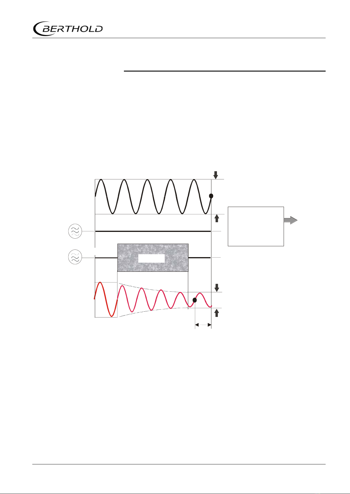
3.1 Principle of Measurement
As the microwaves pass through the product, their propagation ve-
locity is slowed down (= phase shift) and their intensity is attenu-
ated (= attenuation). Figure 3-1 illustrates the principle of meas-
urement: Compared to a reference signal, the propagation velocity
of microwaves passing through the product is slowed down (phase
shift) and their intensity (attenuation) is reduced.
The prerequisite is that the product being measured shows dielectric
properties. Generally, water is a very distinct dielectric fluid. The
water or dry mass concentration can therefore be determined by
measuring the phase shift and/or attenuation.
The concentration to be detected in the product is therefore in good
approximation linearly dependent on the phase shift and the atten-
uation. For this reason, we can measure the concentration or the
dry matter content of the product using a linear calibration (see
chapter 3.2 Calculation of Measured Values).
Figure 3-1:
Schematic diagram:
Change in microwave
by product
Phase shift
Product
Phase comparison
--> Phase
Amplitude comp.
--> Attenuation
Reference path
Reference signal
Measurement signal
Measured value:
Concentration %TS
HF- sources
Transmitter Receiver

Chapter 3. System Description
18 MicroPolar Brix (++) LB 565
3.2 Calculation of Measured Values
The microwave parameters phase and attenuation are calibrated
according to an automatic plausibility analysis.
During calibration, the phase and/or attenuation of a concentration
value (or density value) are assigned through sampling. The cali-
bration is done automatically and the sampling process is sup-
ported by the evaluation unit.
Which of the parameters (phase, attenuation or both) will be used
for the calibration depends on the size and interference of the meas-
uring effect. For example, the attenuation is significantly more sen-
sitive to electrolytic conductivity (salt content).
In many cases, the pure phase measurement is recommended and
calculated as follows:
Measured value = A · Phase + C Eq. 3-1
where:
Measured value Concentration / Moisture / Dry matter
A, C Coefficients of the respective calibration
function
The LB 565 allows you to calibrate, display and output two concen-
trations: Con1 and Con2. You have to enter the calibration coeffi-
cients separately for concentration 1 and 2. For more information
please refer to the Software Manual.

Chapter 3. System Description
MicroPolar Brix (++) LB 565 19
3.3 Temperature Compensation
Temperature compensation (TC) is required for fluctuating product
temperature. It is generally advisable to provide a temperature
compensation, i.e. a temperature signal (0/4...20 mA or PT100) to
be connected to the evaluation unit and, optionally, to enable the
compensation in the evaluation unit. The evaluation unit is designed
so that the required TC’s can be calculated automatically. The vari-
ation in temperature where TC becomes absolutely essential is de-
pendent on the product and on the water content. In the first ap-
proximation, ±2° C should be set as fluctuation limit.
TIP
A TC has to be carried out whenever you are working with cooling
crystallizers.
For example, if the product temperature is measured via the PT100
input, then Eq. 3-1 is expanded as follows:
Measured value = A · Phase + D · Tmeas + C Eq. 3-2
where:
Measured value Concentration / Moisture / Dry matter
A, D, C Coefficients of the calibration function
Tmeas Product temperature
How to work with the temperature compensation is described in de-
tail in the Software Manual.
Chapter 3. System Description
20 MicroPolar Brix (++) LB 565
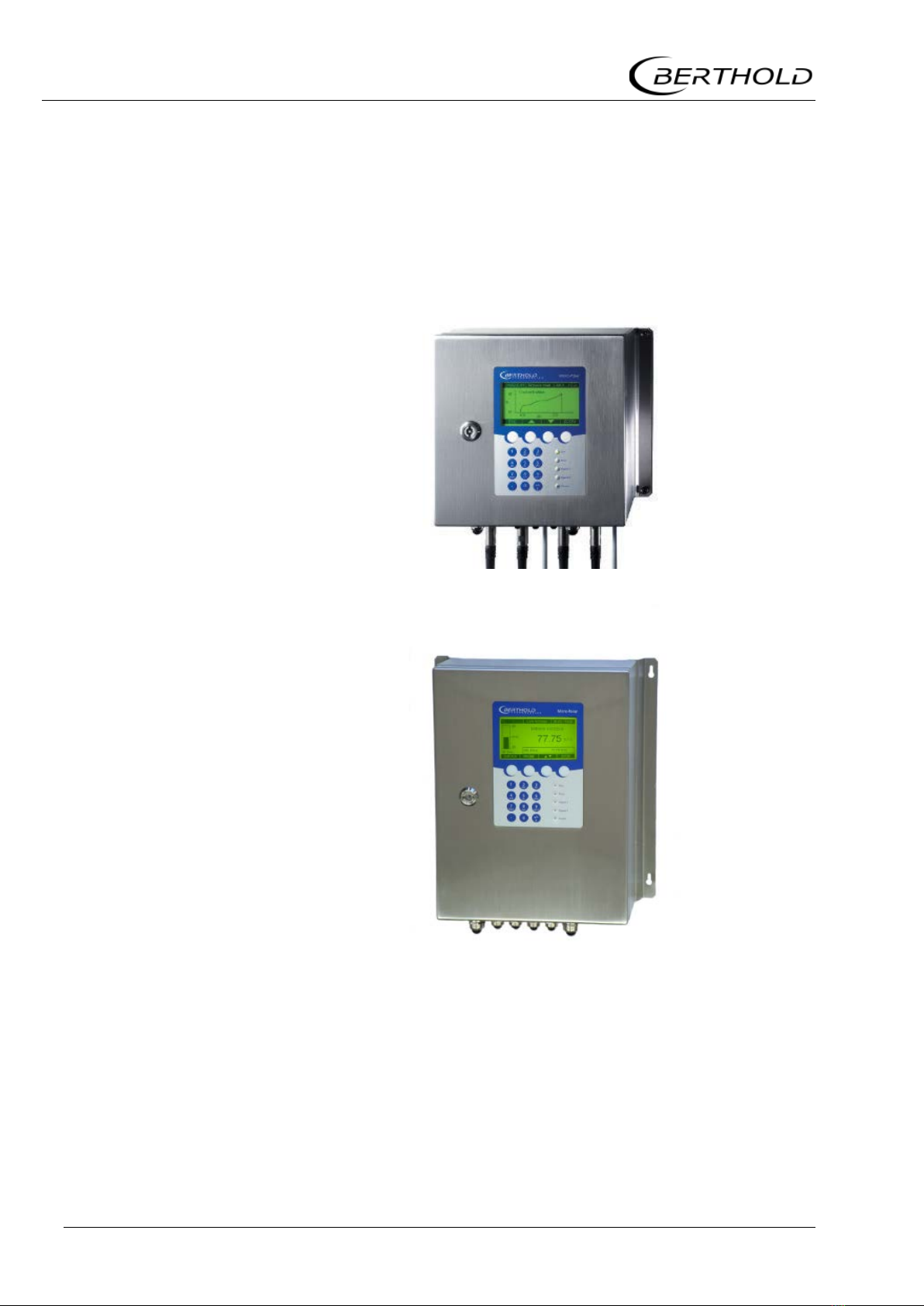
3.4 Mechanical Components
The measuring system consists of an evaluation unit, a probe and a
set of special high-frequency cables (short HF cable). The evaluation
unit is available in two versions: the standard model MicroPolar Brix
LB 565 and the high dynamics version MicroPolar Brix ++ LB 565
(see Figure 3-2 and Figure 3-3).
Figure 3-2:
Evaluation unit
MicroPolar Brix
LB 565
Figure 3-3:
Evaluation unit
MicroPolar Brix ++
LB 565
Table of contents
Other Berthold Measuring Instrument manuals

Berthold
Berthold DuoXpert LB 476 Level+ User manual

Berthold
Berthold DUO XPERT LB 470RID User manual

Berthold
Berthold LB 9510 User manual

Berthold
Berthold castxpert LB 452 User manual

Berthold
Berthold BTwave LB 571-02 User manual

Berthold
Berthold Duo Xpert LB 478 MPLM User manual

Berthold
Berthold Duo XPERT LB 470 Level User manual

Berthold
Berthold LB 444 User manual

Berthold
Berthold Duo Series User manual

Berthold
Berthold MicroPolar LB 566 User manual


