2) Select a suitable test method to perform the measurement, the reading
will show on LCD, check the Figure below:
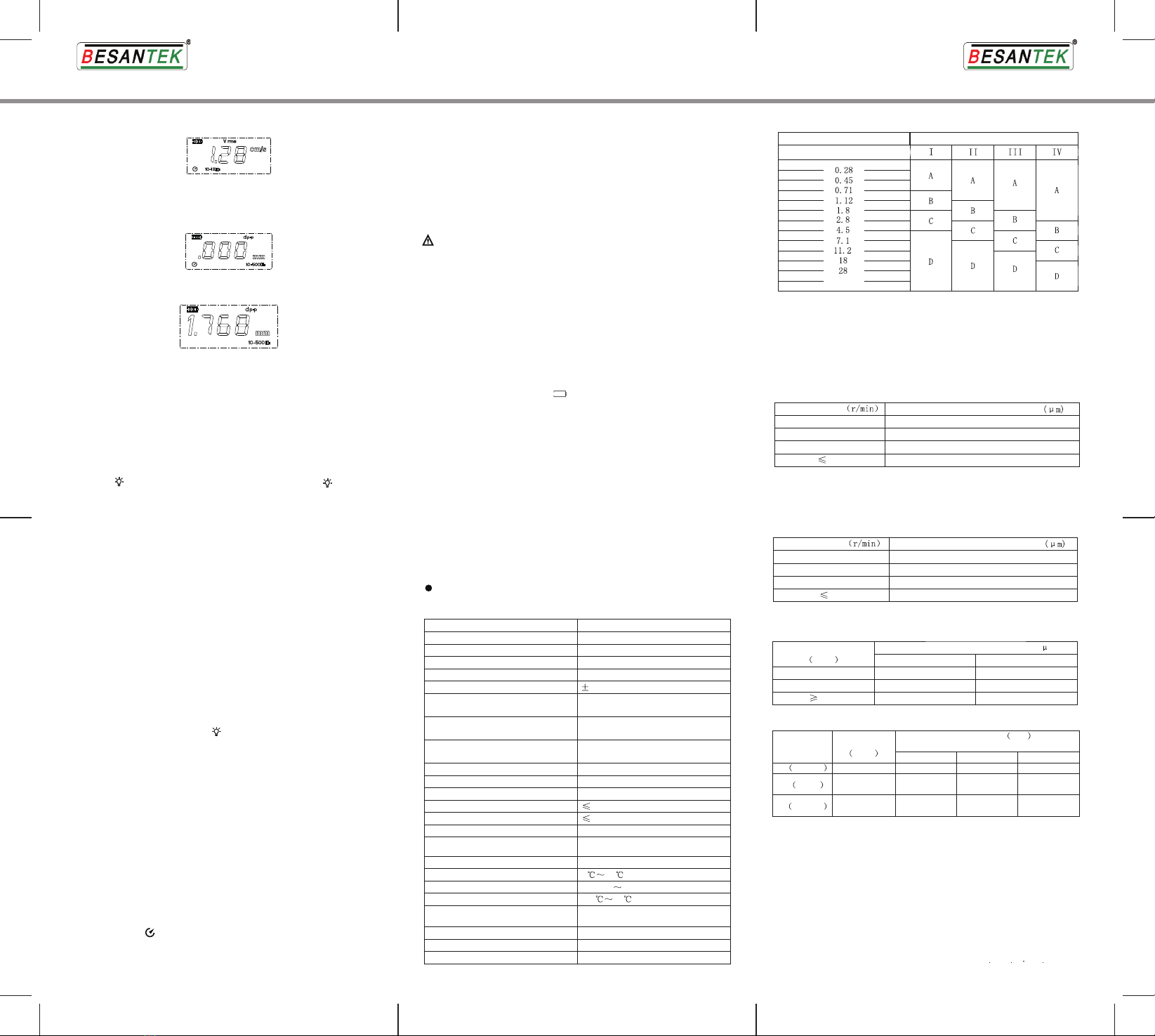
3. Measuring Displacement
1) Press “ D” to enter displacement mode, LCD will show dp-p, 10-500Hz
and mm icons, See the Figure below for details:
2) Select a suitable test method to perform the measurement, the reading
will show on LCD, check the Figure below:
4. Max. Mode
Press MAX button in measuring mode to capture Max. reading, MAX icon
displays simultaneously and the captured Max. reading for the
measurement appears. Repress to disable the function.
5. Data Hold
Press HOLD to enter data hold mode, indicated by HOLD icon on LCD,
and the measured value currently obtained will be frozen. Repress to
disable the function.
6. Backlit Display
Press “ ” button to access backlight mode, indicated by “ ” on LCD,
then LCD will be totally lit up. Repress to exit the function.
7. Record Data
Press “REC” to enter manual recording mode, the Tester shows “DATA”
icon and records currently measured readings. DATA icon disappears in
0.5s. Press REC again to record next data. Long press REC to enter auto
recording mode , DATA flashes on LCD and the Tester will automatically
record the currently measured values at a preset time interval ( See
“ Setting the Menu ” for details ) and exit this function if auto recording
time exceeds 1999 maximum number.
8. Read Data
Press “READ” button in order to read recorded data. LCD shows both
“ ----- ” on reading and No. display zones if the memory is blank. The
Tester will enter measuring mode in 0.5s. If there is any data, the Tester
will automatically display the lasted recorded data and its NO., then press
▼/ ▲to decrease/increase recording No. and view corresponding data;
long press▼/ ▲ to decrease/increase recording No. and view data
quickly; Or press REC button to increment data No. by 100, if recording
No. is less than 100 or you have already go up to No.1999, the Tester will
automatically return to recording No. 1 and its recorded data. Except
buttons mentioned above and “ ” button, other buttons are invalid in
this working mode. Press READ again to exit.
9. Clear Data
Method 1: Press and hold “CLEAR” button while pressing “POWER ” to
turn on the Tester, release “POWER” button, CLR icon will appear on
LCD, indicating the records have already been cleared.
Method 2: Clear data by resetting the Meter to factory default (See
“ Setting the Menu ” for details ).
10. Setting the Menu
Press “MENU” button to enter the menu, it defaults to USB0 item which
keeps USB communication disabled, then press “▲/▼” to change to
USB1 which indicates the communication is enabled. USB icon shows on
LCD under this setup. If READ button is pressed down under menu setup
mode, USB1 icon flashes and data in the memory will be transferred to
PC, with the transfer completed, press ENTER to save and go into next
menu option --- APO setup. APO1 is to enable auto power off function,
indicated by “ ” icon on LCD. Press “▲/▼” to change to APO0 to
disable the function or repress to return to APO1. Finally press ENTER to
save and enter next menu option—Time Interval for auto recording, LCD
★ Measurement with use of short probe is applicable for both high-and
low-frequency vibration.
★ Measurement with use of long-probe is applicable for only low-frequency
vibration. Please use the short probe when measuring acceleration at a
frequency>1kHz.
★ The Tester will turn off automatically after 10 minutes’ inactivity.
Notes:
X. Maintenance
1) Working Environment: BST-VM04 is a precision vibration tester, which
should be protected from any shock, impact, moisture, strong
electromagnetic field, oil and dust.
2) Replacing and Maintaining the battery
a. When low battery indicator “ ” shows, please replace the battery
timely.
b. To avoid any battery leakage or serious damage to the Tester, please
take out the battery if not in use for a long time.
3) Do not attempt to disassemble the Tester to alter its circuits randomly.
4) Cleaning the Casing: Clean the tester surface with soft cloth dampened
with little water; Alcoholic or solvent is not allowed , for it may cause
corrosive damage to the LCD.
XI. Warranty
1) Please refer to Warranty Card for detailed warranty terms
2) The Warranty doesn’t apply to any damage caused by unauthorized
disassembly and misuse from users, self-alteration on warranty card and
absence of purchase proof.
XII. Certification
The Vibration Tester complies with:
EN61326-1:2006
Display Update Period
LCD Display
Accuracy
Displacement Range
Velocity Range
Acceleration Range
Vibration Collection
Technical Parameters
10HZ ~ 500HZ
XIII. Technical Specifications
Specifications
Piezoelectric accelerometer
0.01cm/s~19.99cm/s (true valid value)
0.001mm~1.999mm (peak peak value)
(5%+2dgts)
Frequency Range (for Acceleration) 10HZ ~ 10kHZ
Frequency Range (for Velocity) 10HZ ~ 1kHZ
Frequency Range(for Displacement)
Digital; 1999-count
1 second
0.1m/s ~199.9m/s (peak value)
2 2
Low Battery Indicator
Storage Temperature
Working Humidity
Battery Life
Auto Power Off
Backlight Off Time
Working Current
Current Under Sleep Mode
Power 9V alkaline battery
1uA
25mA
Press backlight key to shut off
automatically power off after 10 minutes'
inactivity
20 hours of continuous use
Working Temperature 0 50
20%RH 80%RH
-20 60
Shows when battery voltage<7V
Dimension 166mm X 80mm X 30mm
Weight 395g
Altitude 2000 m
Appendix:
a. Vibration Severity ( IS02372 )
45
Vibration Strength Machinery Category
Vibration velocity Vrms(mm/s)
Note:
(1) I Category: Small Machinery( <15kW); II Category: Medium Machinery
( 15kW~75kW ); III Category: Large Machinery; IV Category: Large
Primary Machinery (the basis ).
(2) A, B, C, D: Vibration Severity. A: Good; B: Satisfactory, C: Unsatisfactory,
D: Unacceptable. The Vrms value should be measured from three axes
of driveshaft.
b. Maximum Vibration Allowed for Machinery with >1 horse power ( NEMA
MG1-12.05)
3000~4000 25.4
1500~2999 38.1
1000~1499 50.8
63.6
Peak-peak displacement amplitude
Rotating speed
999
d. Preformed winding squirrel-cage induction machinery.
Note:
For AC machinery, please use Maximum syn rotation speed; for DC
machinery, select the rotation speed with Max. power; for series-connected
or multipurpose machinery, use the working speed.
c. Maximum Vibration Allowed for Large Induction Machinery ( NEMA MG1-
20.52)
Peak-peak displacement amplitude
Rotating speed
3000 and higher 25.4
1500~2999
999
50.8
1000~1499 63.6
76.2
Two standards above are formulated by National Electrical Manufacturers
Association (NEMA)
50.8 63.6
38.1 50.8
25.4 25.4
Sync rotating speed
720~1499
1500~2999
3000
Peak-peak displacement amplitude ( m)
Plastic support Rigid support
The standard is formulated by American Petroleum Institute.
e. ISO/IS2373 the electric quality standard based on vibration velocity.
80<H<132 132<H<225 225<H<400
Quality grade
600~3600 1.8 2.8 4.5
N Normal
600~1800
1800~3600
0.71
1.12
1.12
1.8
1.8
2.8
600~1800
1800~3600
0.45
0.71
0.71
1.12
1.12
1.8
R Good
S Special
Rotating speed Axis height H mm
maximum vibration velocity rms(mm/s)
r/min
r/min
Grade N limit value recommended in the table is only applicable to common
machinery.
at the moment shows 060, DATA and REC icons, then press “▲/▼” to
increase/decrease the time or long press“▲/▼” to increase/decrease
quickly. The time can be set within 0.5~255 seconds. Finally press
ENTER to save and access next option—factory default, LCD will show
“ DEF? ” ( Pressing ENTER will reset the Tester to factory settings —
USB0, APO1, 60s and clear all recorded data. If with MENU pressed
down, the Tester will go into measurement selected before the menu
setup, or if turning off the Tester when setting the menu, the Tester will
automatically save the setup status, and there is no need to reset after
returning on the Tester ).
** END **
Due to our policy of constant improvement and development, we
reserve the right to change specifications without notice.


