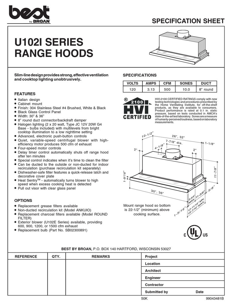
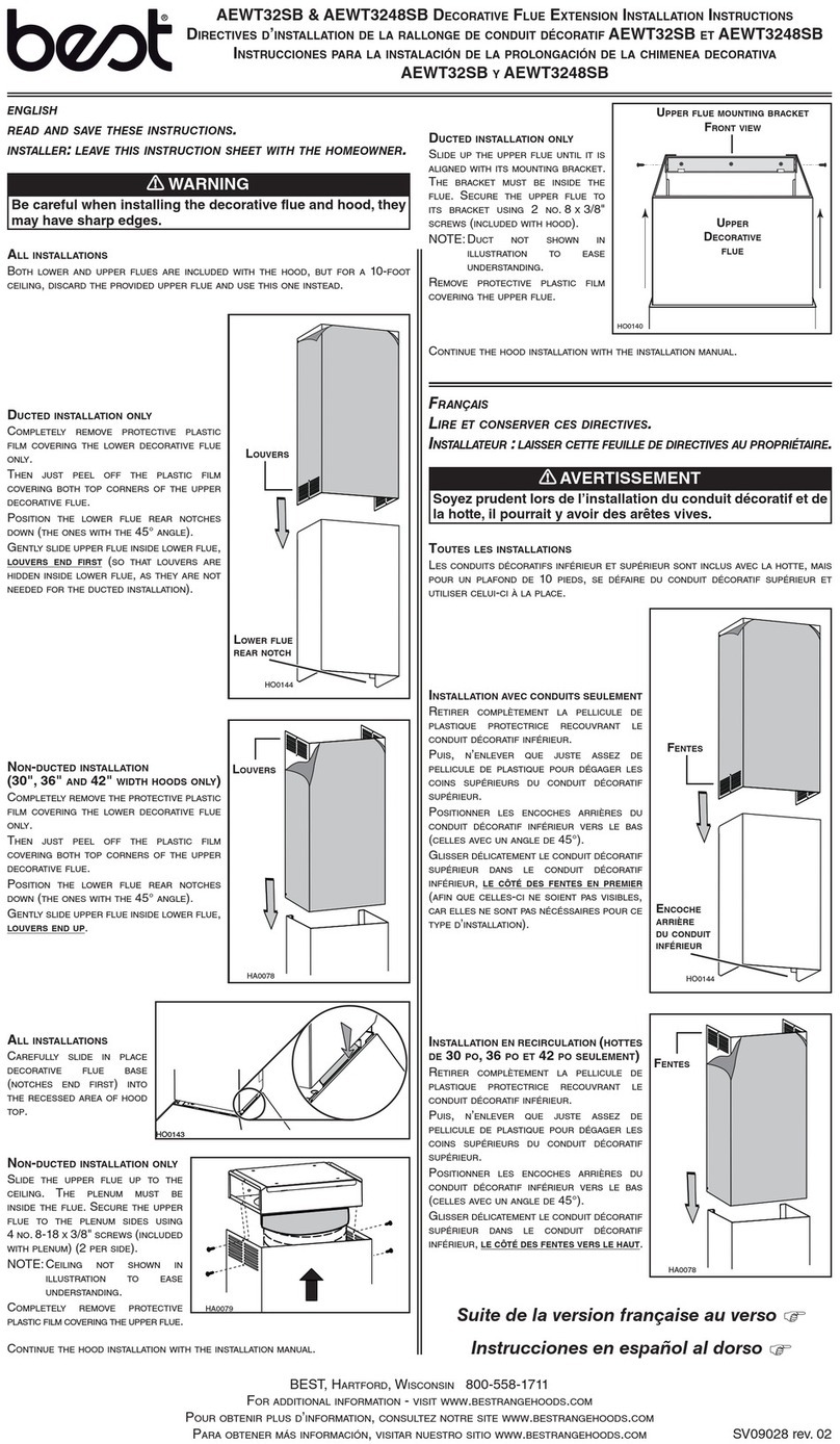
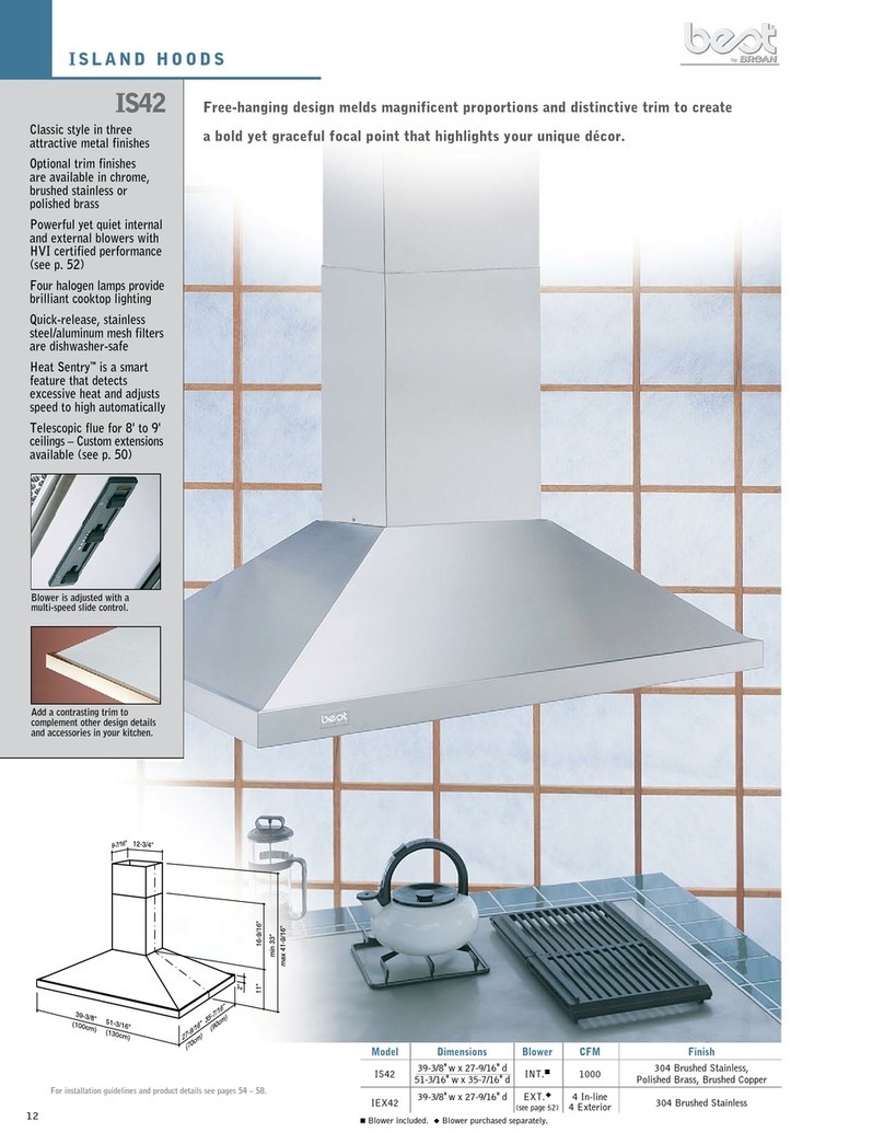
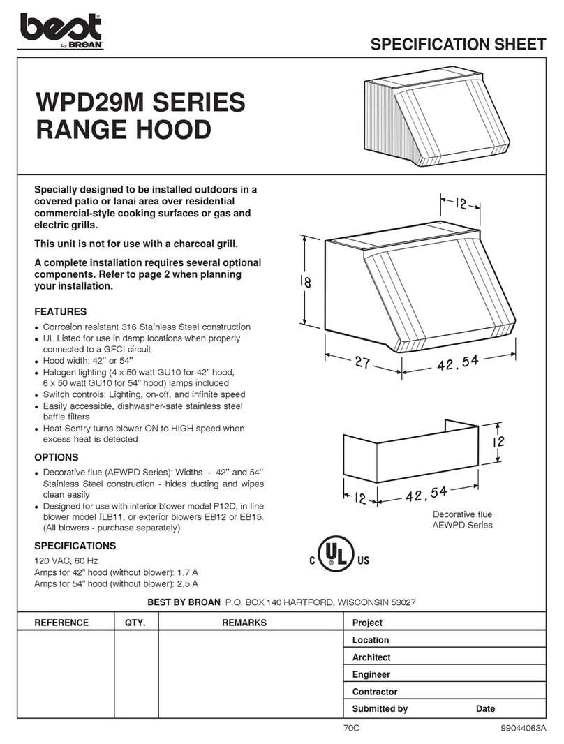
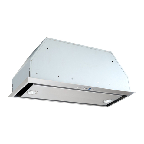
Best IS241 User manual

ENGLISH...................................... 2
FRANÇAIS....................................12
ESPAÑOL..................................... 22
Model IS241 / BER02IS
In USA - BEST Hartford, Wisconsin
In CANADA - BEST Drummondville, QC, Canada
REGISTER YOUR PRODUCT ONLINE AT : www.BestRangeHoods.com/register
For additional Information visit www.BestRangeHoods.com

- 2 -
READ AND SAVE THESE INSTRUCTIONS
WARNING
TO REDUCE THE RISK OF FIRE, ELECTRIC SHOCK, OR INJURY TO PERSONS,
OBSERVE THE FOLLOWING:
1. Use this unit only in the manner intended by the manufacturer. If you have questions,
contact the manufacturer at the address or telephone number listed in the warranty.
2. Before servicing or cleaning unit, switch power off at service panel and lock service
panel to prevent power from being switched on accidentally. When the service
disconnecting means cannot be locked, securely fasten a prominent warning device,
such as a tag, to the service panel.
3. Installation work and electrical wiring must be done by a qualified person(s) in accor-
dance with all applicable codes and standards, including fire-rated construction codes
and standards.
4. Sufficient air is needed for proper combustion and exhausting of gases through the flue
(chimney) of fuel burning equipment to prevent backdrafting. Follow the heating equip-
ment manufacturer’s guidelines and safety standards such as those published by the
National Fire Protection Association (NFPA), and the American Society for Heating,
Refrigeration and Air Conditioning Engineers (ASHRAE), and the local code authorities.
5. When cutting or drilling into wall or ceiling, do not damage electrical wiring and other
hidden utilities.
6. Ducted fans must always be vented to the outdoors.
7. Do not use this unit with any separate solid-state speed control device.
8. To reduce the risk of fire, use only metal ductwork.
9. This unit must be grounded.
TO REDUCE THE RISK OF A RANGE TOP GREASE FIRE:
A. Never leave surface units unattended at high settings. Boilovers cause smoking and
greasy spillovers that may ignite. Heat oils slowly on low or medium settings.
B. Always turn hood ON when cooking at high heat or when flambeing food (i.e. Crepes
Suzette, Cherries Jubilee, Peppercorn Beef Flambe’).
C. Clean ventilating fans frequently. Grease should not be allowed to accumulate on fan or
filter.
D. Use proper pan size. Always use cookware appropriate for the size of the surface
element.
WARNING
TO REDUCE THE RISK OF INJURY TO PERSONS IN THE EVENT OF A RANGE TOP
GREASE FIRE, OBSERVE THE FOLLOWING:*
1. SMOTHER FLAMES with a close-fitting lid, cookie sheet, or metal tray, then turn off the
burner. BE CAREFUL TO PREVENT BURNS. If the flames do not go out immediately,
EVACUATE AND CALL THE FIRE DEPARTMENT.
2. NEVER PICK UP A FLAMING PAN - You may be burned.
3. DO NOT USE WATER, including wet dishcloths or towels - violent steam explosion will
result.
4. Use an extinguisher ONLY if:
A. You know you have a Class ABC extinguisher and you already know how to operate
it.
B. The fire is small and contained in the area where it started.
C. The fire department is being called.
D. You can fight the fire with your back to an exit.
* Based on “Kitchen Fire Safety Tips” published by NFPA.
!
INTENDED FOR DOMESTIC COOKING ONLY
!

- 3 -
!
CAUTION
1. For indoor use only.
2. To reduce risk of fire and to properly exhaust air, be sure to duct air outside. Do not vent
exhaust air into spaces within walls or ceilings or into attics, crawl spaces, or garages.
3. Take care when using cleaning agents or detergents.
4. Avoid using food products that produce flames under the Range Hood.
5. For general ventilating use only. Do not use to exhaust hazardous or explosive materi-
als and vapors.
6. To avoid motor bearing damage and noisy and/or unbalanced impellers, keep drywall
spray, construction dust, etc. off power unit.
7. Your hood motor has a thermal overload which will automatically shut off the motor if it
becomes overheated. The motor will restart when it cools down. If the motor continues
to shut off and restart, have the hood serviced.
8. For best capture of cooking impurities, the bottom of the hood should be a minimum of
24" and a maximum of 30" above the cooking surface.
9. Two installers are recommended because of the large size and weight of this hood.
10. This product is equipped with a thermostat which may start blower automatically. To
reduce the risk of injury and to prevent power from being switched on accidentally,
switch power off at service panel and lock or tag service panel.
11. Use with approved cord-connection kit only.
12. Please read specification label on product for further information and requirements.

- 4 -
PREPARE THE HOOD
Unpack hood and check contents.
You should receive:
1 - Hood
1 - Decorative Flue Assembly
1 - Support Frame
1 - Parts Bag (B080810590) containing:
4 - Mounting Screws (1/4 x 2-3/4”)
11- Mounting Screws (1/8 x 3/8” Pan Head)
4 - Washer ø1/4”
1 - Glass Gasket
1 - Glass Bracket
2 - Side Glass Brackets
1 - Gasket
2 - Halogen Lamps
1 - Parts Bag (B080810114) containing:
1 - Upper Bracket
8 - Mounting Screws (1/8 x 3/8” Pan Head)
2 - Mounting Screws (3/16 x 13/16”)
8 - Washer ø3/16”
1 - Parts Bag (B080810320) containing:
1 - Control Box
1 - Control Box Cover
2 - Mounting Screws (1/8 x 3/8” Pan Head)
2 - Mounting Screws (1/8 x 1/4” Pan Head)
2 - Serrated Washers
1 - Nameplate
1 - Installation Instructions
SUPPORT FRAMEDECORATIVE
FLUE
21 MOUNTING
SCREWS (1/8x3/8”
Pan Head)
2 SERRATED
WASHERS
4 MOUNTING
SCREWS (1/4 x 2-3/4”)
4 WASHERS
Ø1/4”
2 MOUNTING
SCREWS (1/8x1/4”
Pan Head)
8 WASHERS
Ø3/16”
2 MOUNTING
SCREWS (3/16”
x 13/16”)
Control Box
Cover
Gasket
Glass Gasket
Upper Bracket
Glass Bracket
Side Glass
Brackets
Nameplate
Control Box
Halogen Lamps

- 5 -
INSTALL THE DUCTWORK
NOTE: To reduce the risk of fire, use only metal
ductwork.
1. Decide where the ductwork will run between
the hood and the outside.
2. A straight, short duct run will allow the hood
to perform most efficiently.
3. Long duct runs, elbows, and transitions will
reduce the performance of the hood. Use as
few of them as possible.
4. Install a roof or wall cap. Connect 6" round
metal ductwork to cap and work back to-
wards hood location. Use duct tape to seal
the joints between ductwork sections.
INSTALL SUPPORT SYSTEM
1. Assemble the upper half of support frame to
the upper bracket and fix it by means #4
screws (1/8x3/8”).
2. Fix the gasket on the ductwork hole.
3. At hood location, install 2 X 4 cross framing
between ceiling joists using dimensions
shown.
4. Finish the ceiling surface. Be sure to mark
the location of the ceiling joists and cross
framing.
5. Fix the bracket to the ceiling by means of the
4 screws (1/4x2-3/4”) with 4 washers
(ø1/4”).
6. Make sure screws are driven into center of
joists and framing for maximum strength.
HOOD
ROOF CAP
6” ROUND
ELBOW
93/8””
77/8”
UPPER
BRACKET
UPPER
HALF OF
SUPPORT
FRAME
6” ROUND DUCT
EAVE
VENT
DECORATIVE
FLUE
24” TO 30” ABOVE
COOKING SURFACE
CEILING
JOISTS
CROSS
FRAMING
9-3/8”
UPPER
HALF OF
SUPPORT
FRAME
TOP VIEW OF
SUPPORT FRAME
FRONT
SCREWS
(1/8x3/8”)
SCREWS
(1/4X2-3/4”)
WASHERS
(ø 1/4”)
FRONT
GASKET

- 6 -
CONNECT DECORATIVE FLUE
1. Separate the 2 decorative flues; this
operation should be performed with great
care to avoid scratches. Place flues on
the floor and lift the inner flue without tiltins
on deformins the shape of the flues.
2. Secure the upper flue section to the brackets
of the support frame with the 2 screws (3/16
X 13/16”).
3. Insert the lower flue section pushing it
upwards, and make it turn as far as the hole,
which has been made in the lower flue
section, is found available through its lower
opening. Partly screw one screw in the hole
and temporarily rest the lower flue section
on this (screw 1/8x3/8”). When making such
operation mind that the gasket is not
damaged.
LOWER
FLUE
SECTION
BRACKET
OF THE
SUPPORT
FRAME
UPPER
FLUE
SECTION
SCREWS
(3/16X13/
16”)
SCREW
(1/8X3/8”)
7. Separate the blower box and the lower part
of the support frame. Remove the 4 screws.
8. Connect the lower part of the support frame
to the part previously fixed to the ceiling with
8 screws (1/8x3/8”) and 8 washers (ø 3/16”).
9. Adjust the overall height of the support frame.
Loosen and re-tighten the screws in the
height adjustment slots as necessary. Note
that the hood height is 13 - 3/8” and that the
bottom of the hood must be 24” min. and 30”
max. above the cooktop.
FRONT
SCREWS
(1/8X3/8”)
WASHERS
(ø3/16”)
LOWER PART OF
THE SUPPORT
FRAME

- 7 -
INSTALLATION OF GLASS
FRAME
1. Insert the glass gasket along the edges of
the glass.
2. Insert the glass, from the top to the bottom,
over the blower unit and secure it to the
blower by means of the three brackets and
the six screws (1/8x3/8”) which have been
supplied. The brackets must be fixed on the
side of the blower unit which has not got
controls.
Note that the blower unit must be slightly
elevated to allow the glass to fully seat on
blower bracket. Place a block of packins
foam under the blower unit to accomplish
this.
ATTENTION: Not to break the glass, it's of
much importance for the plastic gasket to
cover every part of glass frame and that the
glass is not directly in contact with metal.
Glass frame appliances are part of a
prestigious range of hand crafted cooker
hoods; due to the particular steps of
processing the glass is subjected to, the
glass body could present some deffects and
distortion.
Please be very carefull not to hit the glass
with any objects made of porcelain, metal,
glass or anything else that is very heavy.
GLASS
BLOWER UNIT
GLASS
GASKET
GLASS
BRACKET SIDE GLASS
BRACKETS
CONNECT DUCTWORK
Three people are required to perform the
following operations.
1. Place the hood under the lower part of the
support frame and connect the duct to the
duct collar. Be sure the control side is
orientated properly.
2. Use 6" round metal duct to connect the
duct collar on the hood to the ductwork
above.
3. Use duct tape to make all joints secure and
air tight.
DUCT
6” DUCT
COLLAR
SCREWS
(1/8X3/8”)
FRONT
FRONT
(CONTROL
SIDE)

- 8 -
MOUNT HOOD TO SUPPORT
FRAME
1. Fix controls to the control box inside the
lower section of decorative flue by means of
the 2 screws (1/8x1/4”). Put the cover on the
control box.
2. Fix the control box to the blower housins by
means of the 2 screws (1/8x3/8”) and 2
serrated washers.
Three people are required to perform the
following operations.
3. Install the hood to support frame by 4 screws
(use the screws removed beforehand - 1/8”
x 3/8”).
4. Install the halogen lamps and the grease
filter.
5. Make electrical connections (refer to the
section “WIRING”.
6. Remove the temporary fixing screw of the
lower flue section and lower it in place on
the hood.
WIRING
Note: This range hood must be properly
grounded. The unit should be installed by a
qualified electrician in accordance with all
applicable national and local electrical codes.
1. Remove the wiring box cover. Remove a
knockout from the wiring box.
2. Secure the conduit to the wiring box
through a conduit connector.
3. Make electrical connections. Connect white
to white, black to black and green to green.
4. Replace wiring box cover and screws. Make
sure that wires are not pinched between
cover and box.
WIRING BOX
COVER
SCREWS
(1/8X3/8”)
TOOTHED
WASHERS
SCREWS
(1/8X1/4”)
CONTROLS

- 9 -
MAINTENANCE
Grease Filter
Clean the grease filter frequently. Remove the
grease filter by pulling it downward.Use a warm
detergent solution. Grease filters are dish-
washer safe. Note: Avoid damage to bulbs by
carefully aligning filter openings with bulbs.
Interior Hood Cleaning
DISCONNECT POWER TO HOOD BEFORE
CLEANING!
1. Remove the grease filter as shown above.
2. Remove the light bulbs. (See “HALOGEN
BULBS” on next page.
3. Remove the metal grille held in place with
four (4) screws.
4. Use a soft cloth and mild detergent solution
to wipe interior surfaces clean.
Exterior Hood Cleaning
Stainless steel is one of the easiest materials
to keep clean. Occasional care will help pre-
serve its fine appearance.
Cleaning tips:
OHot water with soap or detergent is all that
is usually needed.
OFollow all cleaning by rinsing with clear water. Wipe dry with a clean, soft cloth to
avoid water marks.
OFor discolorations or deposits that persist, use a non-scratching household
cleanser or stainless steel polishing powder with a little water and a soft cloth.
OFor stubborn cases, use a plastic scouring pad or soft bristle brush together with
cleanser and water. Rub lightly in direction of polishing lines or "grain" of the
stainless finish. Avoid using too much pressure which may mar the surface.
ODO NOT allow deposits to remain for long periods of time.
ODO NOT use ordinary steel wool or steel brushes. Small bits of steel may adhere
to the surface causing rust.
ODO NOT allow salt solutions, disinfectants, bleaches, or cleaning compounds to
remain in contact with stainless steel for extended periods. Many of these com-
pounds contain chemicals which may be harmful. Rinse with water after expo-
sure and wipe dry with a clean cloth.
Painted surfaces should be cleaned with warm water and mild detergent only.
Glass Cleaning
Use a soft cloth and a glass cleaning solution only!
DO NOT use abrasive cloths, steel wool, or scouring pads.
DO NOT use strong cleaning solutions or abrasive powders.
METAL
GRILLE
GREASE FILTER

- 10 -
OPERATION
Controls
The hood is operated using the (5) push-but-
tons located at eye-level, on the front edge of
the hood.
The light switch turns the halogen lights on
and off.
The blower on-off / speed 1 switch turns the
blower on to its lowest running speed. Turn
the blower off by pressing this switch a sec-
ond time.
The blower speed 2 switch turns the blower on to medium-low running speed.
Pressing this switch a second time sets a timer which keeps the blower operating
at this speed for 10 minutes.
The LED will blink during this time and the blower will shut off automatically.
The blower speed 3 and blower speed 4 switches operate the same as blower
speed 2 switch except: Blower speed 3 is medium-high and blower speed 4 is
high.
At the end of each working time of 30 hours, all the leds blink at the same time;
this indicates that the grease filter need to be cleaned.
Once the clean grease filters are on, push the “blower speed 2 switch” twice (or
else the “blower speed 3 switch” or the “blower speed 4 switch”) during the blink
of the LED, to make the count down start again.
HEAT SENTRY™
Your hood is equipped with a HEAT SENTRY™ thermostat. This thermostat is a
device that will turn on or speed up the blower if it senses excessive heat above
the cooking surface.
1) If blower is OFF - it turns blower ON to HIGH speed.
2) If blower is ON at a lower speed setting - it turns blower up to HIGH speed.
When the temperature level drops to normal, the blower will return to its original
setting.
WARNING
The HEAT SENTRY thermostat can start the blower even if the hood is turned
OFF. When this occurs, it is impossible to turn the blower OFF with its switch.
If you must stop the blower, do it from the main electrical panel.
0-1 234
BLOWER
ON-OFF /
SPEED 1
BLOWER
SPEED 2
LIGHT
SWITCH
BLOWER
SPEED 3
LED LED LED LED
BLOWER
SPEED 4

- 11 -
HALOGEN BULBS
This range hood requires two halogen bulbs
(max 20W, 12V, TYPE MR16 bulb shielded,
GU 5.3 Base).
ALWAYS SWITCH OFF THE ELECTRICITY
SUPPLY BEFORE CARRYING OUT ANY
OPERATIONS ON THE APPLIANCE.
To change bulbs:
1. Remove the grease filter.
2. Remove bulbs by pulling them straight downward. Do not rotate bulbs.
3. Replace bulbs by aligning the bulb’s pins with the receptacle holes and pushing
bulb upward.
IN CASE THE NEW HALOGEN BULB DOES NOT LIGHT UP ONCE IT IS ON, CALL
THE QUALIFIED PERSON.
FUSE REPLACEMENT
SWITCH OFF THE ELECTRICITY SUPPLY.
Push the lower flue upwards.
Open the electrical box.
Replace with the same type of fuse
(5x20mm, 4A, 125V).
FUSE
ELECTRICAL BOX
WARRANTY
ONE YEAR LIMITED WARRANTY FOR BEST PRODUCTS
Broan-NuTone LLC (Broan-NuTone) warrants to the original consumer purchaser of Best products that such products will be free
from defects in materials or workmanship for a period of one year from the date of original purchase. THERE ARE NO OTHER
WARRANTIES, EXPRESS OR IMPLIED, INCLUDING, BUT NOT LIMITED TO, IMPLIED WARRANTIES OR MERCHANT ABILITY
OR FITNESS FOR A PARTICULAR PURPOSE.
During this one-year period, Broan-NuTone will, at its option, repair or replace, without charge, any product or part which is found
to be defective under normal use and service.
THIS WARRANTY DOES NOT EXTEND TO FLUORESCENT LAMP STARTERS, TUBES, HALOGEN AND INCANDESCENT BULBS,
FUSE, FILTERS, DUCTS, ROOF CAPS, WALL CAPS AND OTHER ACCESSORIES FOR DUCTING. This warranty does not cover
(a) normal maintenance and service or (b) any products or parts which have been subject to misuse, negligence, accident, improper
maintenance or repair (other than by Broan-NuTone), faulty installation or installation contrary to recommended installation
instructions.
The duration of any implied warranty is limited to the one-year period as specified for the express warranty. Some states do not
allow limitation on how long an implied warranty lasts, so the above limitation may not apply to you.
BROAN-NUTONE'S OBLIGATION TO REPAIR OR REPLACE, AT BROAN-NUTONE'S OPTION, SHALL BE THE PURCHASER'S
SOLE AND EXCLUSIVE REMEDY UNDER THIS WARRANTY. BROAN-NUTONE SHALL NOT BE LIABLE FOR INCIDENTAL,
CONSEQUENTIAL OR SPECIAL DAMAGES ARISING OUT OF OR IN CONNECTION WITH PRODUCT USE OR PERFORMANCE.
Some states do not allow the exclusion or limitation of incidental or consequential damages, so the above limitation or exclusion
may not apply to you.
This warranty gives you specific legal rights, and you may also have other rights, which vary from state to state. This warranty
supersedes all prior warranties.
To qualify for warranty service, you must (a) notify Broan-NuTone at the address stated below or telephone number stated below,
(b) give the model number and part identification and (c) describe the nature of any defect in the product or part. At the time of
requesting warranty service, you must present evidence of the original purchase date.
In USA - Best®, 926 W. State Street, Hartford, WI 53027 (800-558-1711)
In Canada - Best®, 550 Lemire Blvd., Drummondville, QC J2C 7W9 (866-737-7770)
www.BestRangeHoods.com

- 12 -
READ AND SAVE THESE INSTRUCTIONS
LISEZ ET CONSERVEZ CES INSTRUCTIONS
AVERTISSEMENTS
POUR REDUIRE LES RISQUES D’INCENDIE, DE DECHARGES ELECTRIQUES OU
DE DOMMAGES AUX PERSONNES, OBSERVEZ LES INSTRUCTIONS SUIVANTES:
1. N’utilisezcet appareil quecomme cela est indiquépar le constructeur.Si vous avez des
problèmes,contactezlefabriquantàl’adresseouaunumérodetéléphoneindiquésdans
lagarantie.
2. Avantde pourvoir àl’entretienou au nettoyage devotre appareil, éteignez-le autableau
descommandesoubloquezletableaudescommandesafind’éviterdelemettreenmarche
accidentellement.Sivousnepouvezpas bloquer le système permettant d’éteindrevotre
appareil,appliquezunavertissementextérieurd’unefaçonsure,commeparexemple un
panneau,sur le tableaudes commandes.
3. L’assemblageet la connexionélectrique doivent être faitspar des personnesqualifiées
enrespectantles normes etrèglementsen vigueur, ycomprisles normes etrèglements
concernantlespossibilités d’incendie.
4. Ilestindispensablequ’ilyaitsuffisammentd’air pourquelacombustionetl’évacuationdes
gaz à travers le tuyau du brûleur du combustible ait lieu sans retour de flamme. Suivez
lesindicationsdonnéespar lefabricantdubrûleurainsiquelesnormes desécuritécomme
cellesquisontpubliéesparl’AssociationNationalepourla Protection contre les Incendies
NationalFireProtectionAssociation(NFPA)etlaAmericanSocietyforHeating,Refrigeration
andAirConditioningEngineers(ASHRAE),etlesautoritéslocalesen matière de normes.
5. Quandvous coupez oupercez des trousdans le murou le plafond,n’abîmezpas les fils
électriquesou autres.
6. Leventilateur canalisé doit toujours évacuerl’air vers l’extérieur.
7. N’utilisez pas cet appareil avec un appareil contrôlant la vitesse à état solide.
8. Afinde diminuer toutrisque d’incendie n’utilisezque des conduitsen métal.
9. Votre appareil doit être relié à la terre.
ATTENTION - POUR REDUIRE LES RISQUES D’INCENDIE DES MATIERES GRASSES
QUI SONT EN TRAIN DE CUIRE:
A. Ne laissez jamais ni vos éléments chauffants, ni vos casseroles ou poêles sur le feu
sans les contrôler si vous réglez l’apport de chaleur sur une position élevée. Si vos
casseroles ou poêles débordent cela provoque de la vapeur et des éclaboussures de
graisse qui peuvent prendre feu. Chauffez les huiles lentement à feu bas ou moyen.
B. Faites toujours fonctionner votre hotte quand vous cuisez à des températures élevées
ou quand vous cuisinez des plats flambés. (par ex. crêpes Suzette, Cerises “Jubilé”,
Steack au poivre flambé).
C. Nettoyez régulièrement les ailes de vos ventilateurs. Ne permettez pas que la graisse
s’accumule sur le ventilateur ou sur le filtre.
D. Utilisez des casseroles de taille appropriée. Utilisez toujours des ustensiles de cuisson
dont la taille est appropriée à la surface de votre élément de cuisson.
AVERTISSEMENTS
POURREDUIRELES RISQUESDEDOMMAGESAUXPERSONNESAU CASOÙVOTRE
CUISINIEREPRENDRAITFEU,OBSERVEZLESINSTRUCTIONSSUIVANTES:*
1. ETEINDRE LES FLAMMES à l’aide d’un couvercle le plus hermétique possible, une
plaque à gâteaux, ou un plateau en métal, puis éteindre le brûleur. ATTENTION à NE
PAS VOUS BRÛLER. Si les flammes ne s’éteignent pas immédiatement, SORTEZ ET
APPELEZ LES POMPIERS.
2. NE PRENEZ JAMAIS EN MAIN UNE POÊLE OU UNE CASSEROLE QUI A PRIS FEU
- Vous pourriez vous brûler.
3. N’UTILISEZ PAS D’EAU, ni torchons ou serviettes mouillés - vous provoqueriez une
violente explosion de vapeur.
SEULEMENT POUR UTILISATION DOMESTIQUE
!
!

- 13 -
4. Utilisez un extincteur SEULEMENT si:
A. Vous savez que vous avez un extincteur Classe ABC, et vous en connaissez déjà le
mode d’emploi.
B. Ce n’est pas un très gros incendie et qu’il se limite à l’endroi où il a explosé.
C. Vous êtes en train d’avertir les pompiers.
D. Vous avez la possibilité d’essayer d’éteindre l’incendie en ayant le dos tourné vers
une issue.
* D’après les “Suggestions concernant la Sécurité contre les incendies des cuisines”
publiées par NFPA.
ATTENTION
1. Pourusage intérieur seulement.
2. Afin deréduireles risques d’incendie, assurez-vousd’évacuer l’airàl’extérieur. Ne pas
évacuerl’air dans desespaces clos commel’intérieur des mursou plafonds oudans le
grenier,vide sanitaire ougarage.
3. Faites attention lorsque vous utilisez des agents nettoyants ou des détergents.
4. Évitezd'utiliser des produitsalimentaires pouvant produiredes flammes sousla hotte.
5. N’utilisezcet appareil quepour une ventilationgénérale. Ne l’utilisez paspour évacuer
des matières ou des vapeurs dangereuses ou explosives.
6. Pour éviter de causer des dommages au moteur et de rendre les rotors bruyants et/ou
nonéquilibrés,gardezvotreappareil à l’abri des poussièresdegypseetde construction
ou de rénovation, etc.
7. Le moteur de votre ventilateur possède une protection thermique qui l’éteindra
automatiquement s’il devient surchauffé. Il redémarrera automatiquement une fois
refroidi.Silemoteurcontinueàs’éteindreetàseremettre en marche, faites vérifier votre
hotte.
8. Pourune meilleur évacuationdesodeurs de cuisson,lebas de lahottedevrait être à un
minimum de 24 po et à un maximum de 30 po au-dessus de la surface de cuisson.
9. Deux installateurs sont recommandés lors de l’installation étant donné la grande
dimension et le poids de cette hotte.
10. Ceproduitestdotéd’unthermostatpouvantactiverautomatiquementle ventilateur. Pour
réduirelerisquedeblessuresetéviterl’activationaccidentelle,coupezlecourantdepuis
lepanneaud’alimentationélectrique etverrouillez-leouapposezsurcelui-ciune étiquette
de couleur vive.
11.Utilisez uniquement avec unensemble de cordond’alimentationapprouvé.
12. Nous vous recommandons de lire l’étiquette indiquant les caractéristiques de votre
appareilpour de plusamples renseignements et exigences.
!

- 14 -
PREPAREZ LA HOTTE
Enlever la hotte dans l’emballage et controller le
contenu.
Vous devez recevoir :
1 - Hotte
1 - Conduit décoratif
1 - Structure de support
1 - Sachet (B080810590) avec:
4 - Vis d’assemblage 1/4 x 2-3/4” (6 x 70mm)
11 - Vis d’assemblage 1/8 x 3/8” (3.9 x 9.5mm)
Tête ronde
4 - Rondelles ø1/4” (ø 6.4mm)
1 - Garniture verre
1 - Etrier verre
2 - Etrieres laterales verre
1 - Garniture plastique
2 - Ampoules halogènes
1 - Sachet (B080810114) avec:
1 - Plaque supérieure
8 - Vis d’assemblage 1/8 x 3/8” (3.9 x 9.5mm)
Tête ronde
2 - Vis d’assemblage 3/16 x 13/16” (M4 x 20mm)
8 - Rondelles ø3/16” (ø 4.5mm)
1 - Sachet (B080810320) avec:
1 - Boîte commandes
1 - Couvercle commandes
2 - Vis d’assemblage 1/8 x 3/8” (3.9 x 9.5mm)
Tête ronde
2 - Vis d’assemblage 1/8 x 1/4” (3.9 x 6mm) Tête
ronde
2 - Rondelles dentées
1 - Plaquette logo
1 - Instructions pour l’installation
STRUCTURE DE
SUPPORT
CONDUIT
DECORATIF
Couvercle
Commades
Garniture
Plastique
Garniture Verre Plaque
supérieure
Plaquette
LogoBoîte
Commades
4 VIS D’ASSEMBLAGE
1/4 x 2-3/4” (6x70mm)
Etrier Verre
Etrieres
Laterales
Verre
21 VIS
D’ASSEMBLAGE
1/8x3/8”
(3.9x9.5mm)
Tête ronde
2 RONDELLES
DENTEES
4 RONDELLES
Ø1/4” (Ø6.4mm)
2 VIS
D’ASSEMBLAGE
1/8x1/4”
(3.9x6mm) Tête
ronde
8 RONDELLES
Ø3/16”
(Ø4.5mm)
2 VIS
D’ASSEMBLAGE
3/16” x 13/16”
(M4 x 20mm)
Ampoules
halogènes

- 15 -
INSTALLATION DU SYSTEME
D’EVACUATION
REMARQUE: Pour réduire les risques
d’incendie, n’utilisez que des tuyaux en métal.
1. Décidez où le tuyau doit être installé, entre
votre hotte et l’extérieur.
2. Un tuyau droit et court permettra à votre hotte
de fonctionner d’une façon plus efficace.
3. Un tuyau long avec des coudes et des
transitions réduira le bon fonctionnement
de votre hotte. En utiliser le moins possible.
4. Installez un couvercle sur le toit ou au mur.
Reliez un tuyau en métal rond de 6”
(150mm) au couvercle et faites-le aller
jusqu’à l’empla-cement de votre hotte.
Rendez les jonctions du tuyau hermétiques
au moyen d’un ruban pour tuyaux.
INSTALLATION DE LA
STRUCTURE DE SUPPORT
1. Assembler la partie supérieure de la
structure de support à la plaque supérieure
et fixez-la au moyen des 4 vis 1/8x3/8”
(3,9x9,5mm).
2. Fixer la garniture en plastique à la plaque
supérieure.
3. Installez, à l’emplacement de votre hotte,
un cadre croisé de 2 x 4 entre les solives du
plafond en suivant les dimensions qui vous
sont indiquées.
4. Perfectionnez la surface du plafond.
DE 24” À 30” AU-DESSUS
DU PLAN DE CUISSON
TROU
D’ÉVA-
CUATION
TUYAU ROND
DE 6” (150mm)
COUVERCLE
DU TOIT
COUDE ROND
DE 6”
CONDUIT
DÉCORATIF
HOTTE
SOLIVES DU
PLAFOND
93/8” (250mm)
7 7/8”
(198mm)
PLAQUE
SUPERIEURE
PARTIE
SUPERIEURE
DE LA
STRUCTURE
DE
SUPPORT
9-3/8”
(250mm)
PARTIE
FRONTALE
VIS 1/8x3/8”
(3,9X9,5mm)
VIS 1/4x2-3/4”
(6X70mm)
RONDELLES
ø1/4”
(6,4mm)
PARTIE
FRONTALE
GARNITURE PLASTIQUE
VUE DE HAUT DU CADRE
CROISÉ
PARTIE
SUPERIEURE
DE LA
STRUCTURE
DE SUPPORT
CADRE
CROISÉ

- 16 -
Assurez-vous de bien marquer l’emplacement des solives et du cadre croisé au
plafond.
5. Fixer la plaque au plafond au moyen des 4 vis 1/4x2-3/4” (6x70mm) avec 4
rondelles ø1/4” (6,4mm).
6. Assurez-vous que les vis soient bien
centrées dans les solives et dans le cadre
croisé de sorte que le tout soit bien solide.
7. Separer le groupe moteur e la partie
inférieure de la structure de support. Enlever
les 4 vis.
8. Assemblez la partie inférieure de la structure
de support à la partie qui a été fixée
précédemment au plafond au moyen de 8
vis 1/8x3/8” (3,9x9,5mm) et de 8 rondelles
ø3/16” (4,5mm).
9. Réglez la hauteur totale de la structure de
support. Désserrez et resserrez les vis dans
les fissures permettant de régler la
hauteur selon ce qui est nécessaire.
Considérez que la hauteur de votre hotte
est de 13 - 3/8” et que le bas de votre hotte
doit être à entre 24” et 30” au maximum au-
dessus du plan de cuisson.
INSTALLATION DE LA
CHEMINEE TELESCOPIQUE
1. Séparer les 2 tuyaux décoratifs; cette
opération doit être réalisée en faisant
particulièrement attention pour éviter des
rayures. Positionner les tuyaux au sol
et soulever le tuyau interne en veillant à
ne pas les plier ni à les déformer.
2. Fixer la cheminée supérieure aux étriers de
la structure de support à l'aide des 2 vis 3/
16x13/16” (M4x20mm).
3. Insérez la cheminée inférieure en la
poussant vers le haut. Faites-le tourner
jusqu’à ce que le trou, qui a été fait dans la
cheminée inférieure, soit disponible à
travers son ouverture inférieure.
Serrez partiellement une vis 1/8x3/8”
(3,9x9,5mm) dans le trou et appuyez
provisoirement la cheminée inférieur à celle-
ci. En faisant ceci, faites attention à ne pas
abîmer la garniture.
CHEMINEE
INFERIEURE
ETRIER DE LA
STRUCTURE DE
SUPPORT
CHEMINEE
SUPERIEURE
VIS
3/16x13/16”
(M4X20mm)
VIS
1/8x3/8”
(3,9X9,5mm)
RONDELLES
ø3/16” (4,5MM)
VIS
1/8X3/8”
(3,9X9,5MM)
PARTIE
FRONTALE
PARTIE INFERIEURE
DE LA SCRUCTURE
DE SUPPORT

- 17 -
MONTAGE DE L’ELEMENT
DECORATIF EN VERRE
1. Insérez la garniture du verre le long des
bords du verre.
2. Insérez le verre, du haut en bas, dans le
groupe moteur et fixez-le à celui-ci au
moyen des 3 étrieres et des 6 vis en dotation
1/8x3/8” (3,9x9,5mm). Les étrieres doivent
être fixées sur les côtés du groupe moteur
où il n’y a pas les commandes.
Veiller à ce que le groupe moteur soit
légèrement rehaussé de telle sorte que le
verre puisse être parfaitement placé à
hauteur des brides de fixation de l’unité.
Placer un bloc de matériau expansé sous
l’unité aspirante pour compléter
l’installation.
ATTENTION: Il est important que le joint en
plastique soit bien mis en place, et que le
bord du verre n'entre pas en contact direct
avec le métal, car il risquerait de se casser.
Les hottes dotées d'un élément décoratif en
verre font partie d'une gamme d'articles
"haut de gamme" fabriqués artisanalement;
l'élément en verre peut présenter quelques
petits défauts de déformation, liés aux
traitements auxquels il a dû être soumis.
Faites très attention à ne pas heurter bru-
squement la partie en verre avec des objets
en porcelaine, métal, verre ou autres objets
lourds au risque de le casse.
VERRE GARNITURE DU
VERRE
GROUPE MOTEUR
CONNEXION DU SYSTEME
D’EVACUATION
Il faut 3 personnes pour effectuer les
opérations suivantes.
1. Approcher maintenant la hotte à la partie
inférieure de la structure de support et
raccorder le tuyau d'évacuation de l'air à la
bride de jonction. S’assurer que le côté de
commandes est correctement orienté.
2. Reliez la bride de jonction au système
d’évacuation qui se trouve au-dessus au
moyen d’un tuyau rond en métal de 6”
(150mm).
3. Utilisez du ruban pour tuyauterie afin de
rendre toutes les jonctions sures et étan-
ches.
TUYAU
ROND DE
6”
(150MM)
ETRIER
VERRE
ETRIERES
LATERALES VERRE
VIS 1/8x3/8”
(3,9X9,5mm)
BRIDE DE
JONCTION
PARTIE
FRONTAL
PARTIE
FRONTAL
(POSITION
COMMANDES)

- 18 -
ASSEMBLAGE DE VOTRE
HOTTE A LA STRUCTURE DE
SUPPORT
1. Fixer les commandes à l’équerre qui se
trouve à l’intérieur de la cheminée inférieure
au moyen des 2 vis 1/8x1/4” (3,9x6mm).
Appuyez le couvercle sur la boîte des
commandes.
2. Fixez la boîte des commandes au support
au moyen des 2 vis 1/8x3/8” (3,9x9,5mm) et
des 2 rondelles dentées.
Il faut 3 personnes pour effectuer les
opérations suivantes.
3. Fixer la hotte à la structure, à l'aide des 4 vis
fournis (utiliser les vis déposées
préalablement - 1/8”x3/8” - 3.9x9.5mm).
4. Monter les lampes halogènes et le filtre à
graisse.
5. Effectuez le raccordement électrique
(référez-vous au chapitre “INSTALLATION
ELECTRIQUE”).
6. Eliminer la vis de fixation provisoire de la
cheminée inférieure et placez celle-ci
définitivement en l’appuyant à la hotte.
COUVERCLE DE LA BOÎTE
DE CONNEXION
INSTALLATION ELECTRIQUE
Remarque: Ce modèle de hotte doit être relié
à la terre correctement. Cet article devrait
être installé par un électricien qualifié selon
les lois nationales et locales en matière
d’électricité.
1. Enlevez le couvercle de la boîte de
connexion électrique. Ouvrez un trou de la
boîte de connexion électrique.
2. Fixer le “conduit” au boîtier de connexion
à l’aide d’un connecteur approprié pour
ce “conduit”.
3. Faites le raccordement électrique. Reliez le
blanc au blanc, le noir au noir et le vert au
vert.
4. Remettez le couvercle de la boîte de
connexion et les vis. Assurez-vous que les
fils se sont pas coincés entre le couvercle et
la boîte.
COMMANDES
VIS
1/8x1/4”
(3,9X6mm)
VIS 1/8x3/8”
(3,9X9,5mm)
RONDELLES
DENTEES

- 19 -
ENTRETIEN
Grille anti-graisse
Nettoyez la grille anti-graisse fréquemment. Enlevez la
grille anti-graisse en la tirant vers le bas.
Utilisez une solution détergente tiède. La grille
anti-graisse peut être lavée au lave-vaisselle.
Remarque: Evitez d’abîmer les ampoules en
alignant soigneusement les ouvertures de la
grille avec les ampoules.
Nettoyage de l’intérieur de votre hotte
DEBRANCHEZ VOTRE HOTTE AVANT DE LA
NETTOYER!
1. Enlevez la grille anti-graisse comme cela
est indiqué plus haut.
2. Enlevez les ampoules. (Voir “AMPOULES
HALOGENES” à la page suivante).
3. Enlevez la grille en métal en dévissant les
quatre (4) vis qui la fixent.
4. Lavez l’intérieur de votre hotte au moyen
d’un chiffon doux imprégné d’une solution
contenant un détergent neutre.
Nettoyage de l’éxterieur de votre hotte
L’acier inoxydable est une des matières les plus
faciles à nettoyer. Un entretien de temps en
temps permettra de le conserver en parfait état. Conseils pour le nettoyage:
OEau chaude et savon ou détergent est tout ce qui est normalement nécessaire.
OAprès chaque nettoyage, rincez bien à l’eau claire. Essuyez avec un chiffon
propre et doux afin d’éviter les taches d’eau.
O
Si des décolorations ou des dépôts persistent, utilisez un nettoyant domestique non abrasif
ou de la poudre pour l’acier inoxydable et un peu d’eau et un chiffon doux.
ODans les cas difficiles, utilisez une éponge en plastique ou une brosse douce
avec du nettoyant et de l’eau. Frottez légèrement en suivant la direction du
polissage ou du “grain” de l’acier inoxydable. Evitez de frotter trop fort afin de ne
pas abîmer la surface.
ONE LAISSEZ PAS les taches trop longtemps.
ON’UTILISEZ PAS de laines d’acier ordinaires ou des brosses en acier. Des débris
d’acier pourraient adhérer à la surface et causer de la rouille.
ONE PERMETTEZ PAS que des solutions salées, des désinfectants, des
blanchissants ou des produits nettoyants restent en contact avec l’acier pendant
longtemps. Beaucoup de ces produits contiennent des produits chimiques qui
pourraient causer des dommages. Rincez à l’eau immédiatement s’ils entrent en
contact et essuyez avec un chiffon humide.
Les surfaces peintes doivent être nettoyées avec de l’eau tiède additionnée d’un
détergent doux seulement.
Nettoyage du verre
Utilisez seulement un chiffon doux et un produit nettoyant pour le verre!
N’UTILISEZ PAS d’éponges abrasives, de laine d’acier ou de produits dégraissants
N’UTILISEZ PAS de solutions nettoyantes fortes ni de poudres abrasives.
GRILLE ANTI-GRAISSE
GRILLE EN
MÉTAL

- 20 -
FONCTIONNEMENT
Commandes
Votre hotte fonctionne grâce aux (5) boutons
sur lesquels vous devez appuyer et qui se
trouvent à la hauteur de vos yeux, sur le devant
de votre hotte.
Le bouton de la lumière allume et éteint les
lampes halogènes.
Le bouton ON/OFF vitesse 1 du ventilateur
fait fonctionner le ventilateur à la vitesse la plus
basse.Vous éteignez le ventilateur en appuyant
sur le bouton une deuxième fois.
Le bouton deuxième vitesse fait fonctionner le ventilateur à une vitesse
moyennement basse. En appuyant une deuxième fois sur ce bouton vous faites
fonctionner un timer qui fera fonctionner le ventilateur à cette vitesse pendant 10
minutes. Le voyant lumineux clignotera pendant tout ce temps et le ventilateur
s’arrêtera automatiquement.
Les boutons du ventilateur 3ème et 4ème vitesse font fonctionner ce dernier
comme le bouton deuxième vitesse avec la différence que le bouton 3ème vitesse
est une vitesse moyennement élevée et le bouton 4ème vitesse est une vitesse
élevée.
Au bout d'environ 30 heures de fonctionnement, tous les voyants lumineux se mettent
à clognoter en même temps; cela indique que la grille métallique doive être nettoyée.
Après avoir remonté la grille propres, appuyer 2 fois sur le “bouton deuxième
vitesse” (ou également sur les boutons du ventilateur 3ème et 4ème vitesse) au
même temps les voyants lumineux clignotons, afin de remettre le comptage en
marche.
HEAT SENTRYMC
Votre hotte est munie d’un thermostat HEAT SENTRYMC. Ce thermostat est un
dispositif qui actionnera ou augmentera la vitesse du ventilateur s’il détecte une
chaleur excessive au-dessus de la surface de cuisson.
1) Si le ventilateur n’est pas en marche - il actionnera le ventilateur en haute
vitesse.
2) Si le ventilateur fonctionne en basse vitesse - le ventilateur tournera en haute
vitesse.
Lorsque la température revient à la normale, le ventilateur retourne à sa vitesse
d’origine.
AVERTISSEMENT
Le thermostat HEAT SENTRYMC peu actionner la hotte même si la hotte est
arrêtée. Si tel est le cas, il est impossible de l’arrêter avec l’interrupteur. Si
vous devez arrêter le ventilateur, faites-le à partir du panneau électrique
principal.
0-1 234
LED LED LED LED
VENTILATEUR
VITESSE 4
VENTILATEUR
VITESSE 3
BOUTON DE
LA LUMIERE
VENTILATEUR
ON/OFF
VITESSE 1
VENTILATEUR
VITESSE 2
This manual suits for next models
1
Table of contents
Languages:
Other Best Ventilation Hood manuals

Best
Best KEX8087 User manual

Best
Best CP34 Series User manual

Best
Best WPD39M SERIES User manual

Best
Best D49M30SB User manual

Best
Best K260A series User manual

Best
Best UP27 Series User manual

Best
Best WM45I User manual

Best
Best DPF Series User manual

Best
Best IEX170 User manual

Best
Best WTT32I3 User manual