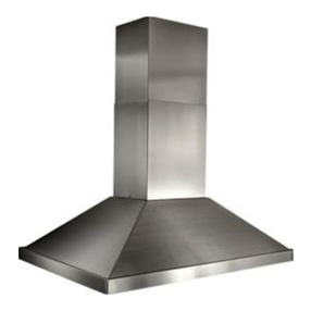
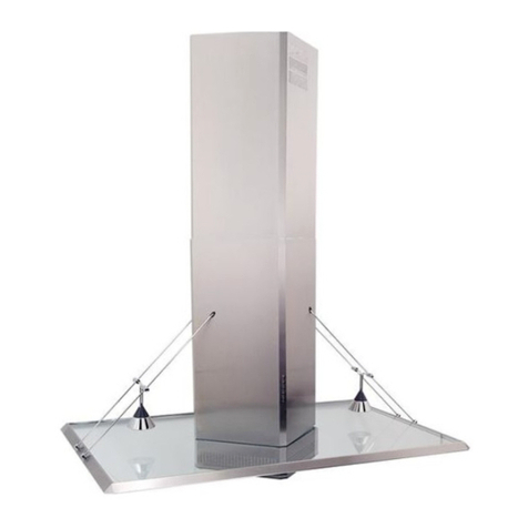
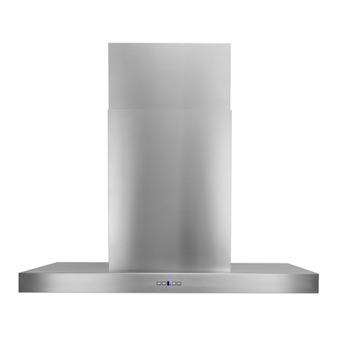
Best ICF6 User manual

In USA - BEST Hartford, Wisconsin
InCANADA -BEST Drummondville, QC, Canada
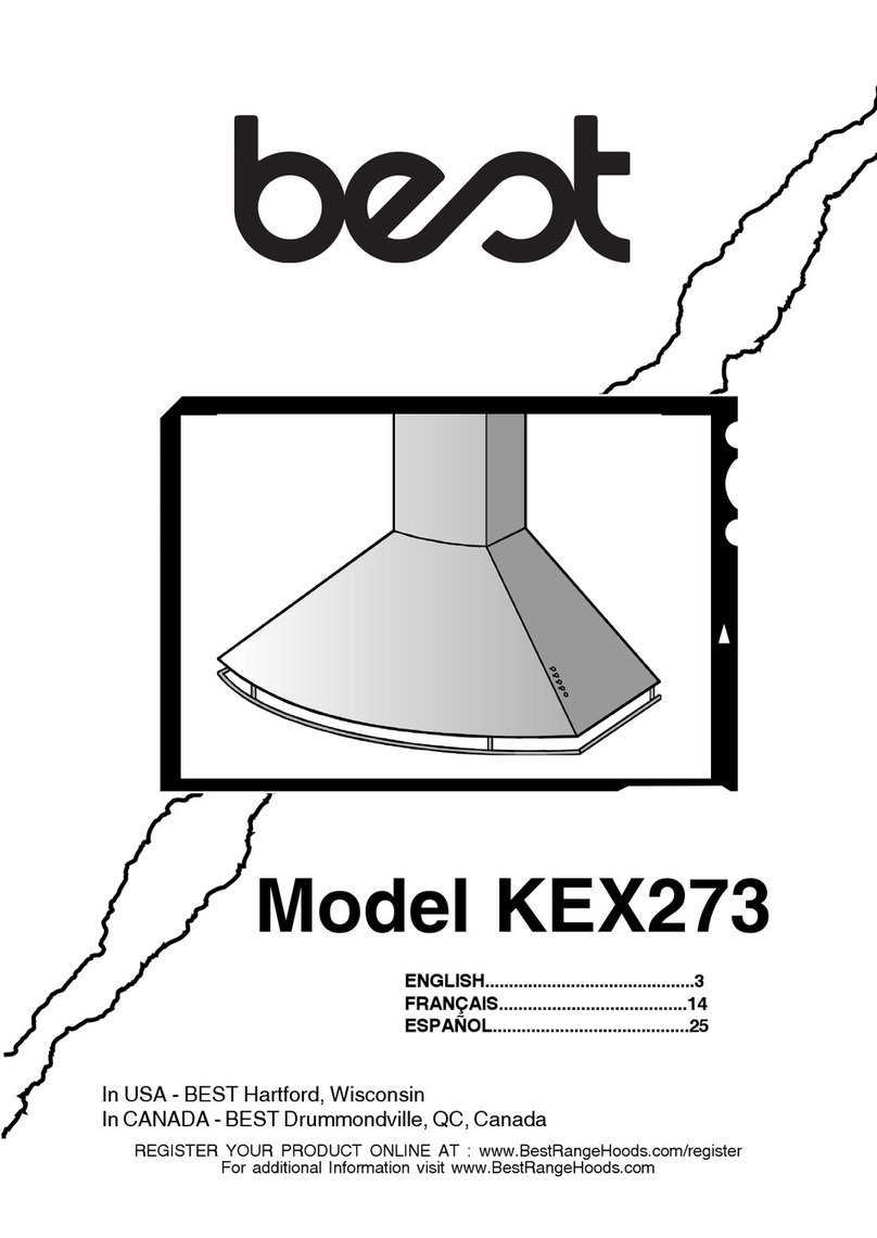
Model ICF6
ENGLISH........................................3
FRANÇAIS...................................21
ESPAÑOL.....................................41
REGISTER YOUR PRODUCT ONLINE AT : www.BestRangeHoods.com/register
For additional Information visit www.BestRangeHoods.com


- 3 -
READ AND SAVE THESE INSTRUCTIONS
WARNING
TO REDUCE THE RISK OF FIRE, ELECTRIC SHOCK, OR INJURY TO PERSONS, OBSERVE
THE FOLLOWING:
1. Usethis unitonly in the manner intendedby themanufacturer. If youhave questions,contact the
manufacturerattheaddressortelephonenumberlistedinthewarranty.
2. Before servicing or cleaning unit, switch power off at service panel and lock service panel to
preventpowerfrombeingswitchedonaccidentally.Whentheservicedisconnectingmeanscannot
be locked, securely fasten a prominent warning device, such as atag, to the servicepanel.
3. Installationworkandelectrical wiringmustbedonebyaqualifiedperson(s)inaccordancewithall
applicablecodes andstandards, includingfire-ratedconstructioncodes and standards.
4. Sufficientairisneededforpropercombustionandexhaustingofgasesthroughtheflue(chimney)
of fuel burning equipment to prevent backdrafting. Follow the heating equipment manufacturers
guidelinesandsafetystandardssuchasthosepublishedbytheNationalFireProtectionAssocia-
tion(NFPA),andtheAmericanSocietyforHeating,RefrigerationandAirConditioningEngineers
(ASHRAE),andthelocalcodeauthorities.
5. Whencuttingordrillingintowallorceiling,donotdamageelectricalwiringandotherhiddenutilities.
6. Ducted fansmust always be vented to the outdoors.
7. Do not use thisunit with any separate solid-statespeed controldevice.
8. To reduce the risk of fire, use only steel ductwork.
GROUNDINGINSTRUCTIONS
Thisappliancemustbegrounded.Intheeventofanelectricalshortcircuit,groundingreducestherisk
of electrical shock by providing an escape wire for the electric current.
WARNING - Improper grounding can result in a risk of electric shock.
Consultaqualified electrician ifthegroundinginstructionsarenotcompletelyunderstood,orifdoubt
existsas towhethertheapplianceis properly grounded.
TO REDUCE THE RISK OF A RANGE TOP GREASE FIRE:
A. Never leave surface units unattended at high settings. Boilovers cause smoking and greasy
spillovers that may ignite. Heat oils slowly onlow ormediumsettings.
B. Always turn hood ON when cooking at high heat or when flambeing food (i.e. Crepes Suzette,
Cherries Jubilee, Peppercorn Beef Flambe).
C. Cleanventilatingfansfrequently.Greaseshould notbeallowedtoaccumulate onfanorfilter.
D. Use proper pan size. Always use cookware appropriate for thesize of thesurface element.
!INTENDED FOR DOMESTIC COOKING ONLY !

- 4 -
WARNING
TO REDUCE THE RISK OF INJURY TO PERSONS IN THE EVENT OF A RANGE TOP GREASE
FIRE,OBSERVETHE FOLLOWING:*
1. SMOTHERFLAMESwithaclose-fittinglid,cookiesheet,ormetaltray,thenturnofftheburner.BE
CAREFULTOPREVENTBURNS.Iftheflamesdonotgooutimmediately,EVACUATEANDCALL
THEFIREDEPARTMENT.
2. NEVERPICK UP AFLAMINGPAN -You maybe burned.
3. DONOTUSE WATER, including wetdishcloths ortowels -violent steamexplosion willresult.
4. Usean extinguisherONLYif:
A. You know you have aClass ABC extinguisherand youalready knowhow tooperate it.
B. Thefireissmallandcontainedin theareawhereitstarted.
C. Thefiredepartmentisbeingcalled.
D. You can fight the fire with your back to an exit.
* Based on Kitchen Fire Safety Tips published by NFPA.
!CAUTION
1. Forindooruseonly.
2. To reducerisk of fire and to properlyexhaust air, be sureto duct air outside.Do not vent exhaust
air into spaces within walls orceilings or into attics, crawl spaces, or garages.
3. Takecarewhenusingcleaningagentsor detergents.
4. Avoidusingfood productsthatproduceflamesundertheRangeHood.
5. For general ventilating use only. Do not use to exhaust hazardous or explosive materials and
vapors.
6. To avoid motor bearing damage and noisy and/or unbalanced impellers, keep drywall spray,
constructiondust, etc. off powerunit.
7. Yourhood motor has athermal overload whichwill automatically shut offthe motorifitbecomes
overheated.Themotorwillrestartwhenitcoolsdown.Ifthemotorcontinuestoshutoffandrestart,
havethe hoodserviced.
8. For bestcapture ofcooking impurities,the bottomof the hoodshould bea minimumof 24" and a
maximumof36"abovethe cookingsurface.
9. Twoinstallersare recommended because ofthe large size andweightof this hood.
10. This product is equipped with a thermostat which may start blower automatically. To reduce the
riskofinjuryandtopreventpowerfrombeingswitchedonaccidentally,switchpoweroffatservice
paneland lockor tagservice panel.
11. Pleasereadspecificationlabel onproductforfurtherinformationandrequirements.
12. The glass panel on this hood is not to be used as a shelf.

- 5 -
LED LAMPS
The hood is provided with LED lamps wich require no maintenance.
CLEANING AND MAINTENANCE
Proper maintenance of the Range Hood will assure proper performance of the unit.
Motor
The motor is permanently lubricated and never needs oiling. If the motor bearings make
excessive or unusual noise, replace the motor with the exact service motor. The impeller
should also be replaced.
Grease Filter
The grease filters should be cleaned frequently. Use a warm detergent solution. Grease
filter are dishwasher safe.
Clean all-metal filters in the dishwasher using a non-phosphate detergent. Discoloration
of the filter may occur if using phosphate detergents, or as a result of local water
conditions - but this will not affect filter performance. This discoloration is not covered by
the warranty. See INSTALL FILTERS section for removal and installation instructions.
Non-ducted Recirculation Filter
The non-ducted recirculation filter should be changed every 6 months. Replace more
often if your cooking style generates extra grease, such as frying and wok cooking. See
INSTALL FILTERS section for removal and installation instructions.
Stainless Steel Cleaning
DO:
Regularly wash with clean cloth or rag
soaked with warm water and mild soap or
liquid dish detergent.
Always clean in the direction of original
polish lines.
Always rinse well with clear water (2 or 3
times) after cleaning. Wipe dry completely.
You may also use a specialized
household stainless steel cleaner.
DONT:
Use any steel or stainless steel wool or
any other scrapers to remove stubborn dirt.
Use any harsh or abrasive cleansers.
Allow dirt to accumulate.
Let plaster dust or any other construction
residues reach the hood. During
construction/renovation, cover the range
hood to make sure no dust sticks to the
stainless steel surface.
Avoid: When choosing a detergent
Any cleaners that contain bleach will attack stainless steel
Any products containing: chloride, fluoride, iodide, bromide will deteriorate surfaces rapidly.
Any combustible products used for cleaning such as acetone, alcohol, ether, benzol,
etc., are highly explosive and should never be used close to a range.

- 6 -
OPERATION
Filter Alarm
After 30 hours of blower operation, the filter alarm is activated and Filter Alarm Indicator
LED turns red. It indicates the grease filters need to be cleaned.
After 120 hours of blower operation, the filter alarm is activated and Filter Alarm Indicator
LED turns red and flashes. It indicates the grease filters need to be cleaned and the
charcoal filters need to be replaced (for non-ducted applications).
After cleaning the grease filters (and/or replacing the charcoal filters), reset the hour counter
by pressing the Filter Alarm / Timer Rest button during display of the alarm.
Auto Shut-Off Feature
If the blower and/or the lights are on continuously for 10 hours without any user interaction
with the controls, the hood will automatically shut off. Press any control button to re-activate
the hood.
HEAT SENTRY
Your hood is equipped with a HEAT SENTRY thermostat. This thermostat is a device that
will turn on or speed up the blower if it senses excessive heat above the cooking surface.
1) If blower is OFF - it turns blower ON to HIGH speed.
2) If blower is ON at a lower speed setting - it turns blower up to HIGH speed.
When the temperature level drops to normal, the blower will return to its original setting.
WARNING
The HEAT SENTRY thermostat can start the blower even if the hood is turned OFF.
When this occurs, it is impossible to turn the blower OFF with its switch. If you must
stop the blower, do it from the main electrical panel.
Controls (Fig.1)
The hood is operated using the (5) push buttons located on the front edge of the hood.
Filter Alarm
Indicator
Filter Alarm /
Timer Reset
Speed
Indicators
Blower
On / Speed
Blower
Off / Speed
Light On
Light Off
When LED is red (motor off) it indicates the
filter alarm. When LED is green flashing, it
indicates timer is activated and Filter Alarm
/ Timer Reset button has been pressed.
When pressing the button during the dis-
play of the filter alarm (blower off) it resets
the filter alarm. When pressing the button
while the blower is on, it activates the ten-
minute timer function and the blower will
automatically turn off in ten minutes.
The green LEDs indicate blower speed.
Activates the blower (at the last speed
used) and increases the blower speed until
the maximum speed is achieved.
Decreases the blower speed. If pressed for
two seconds, the blower will turn off.
Turns lights on
Turns lights off

- 7 -
FIG. 2 FIG. 3
P5
P4
P3
P2
P1
INDICATOR
LIGHT
HOOD CONTROL
Remote Control Functions (Fig.2)
See Controls section on previous page for more information on each function.
Delay - Off
Blower Speed Decrease and Off
Blower Speed Increase and On
Light
CAUTION RISK OF EXPLOSION IF BATTERY IS
REPLACED BY AN INCORRECT TYPE. DISPOSE
OF USED BATTERY TO THE INSTRUCTION.
Battery disposal
When the batteries need to be replaced, dispose of them only and exclusively in the numerous
readily available special waste bins, especially in shops selling electronic consumer goods.
Observance of the regulations on differentiated waste collection, in particular, proper disposal of
used batteries, contributes to preventing possible negative effects on the environment and health.
REMOTE CONTROL
The remote control is linked to the hood at the factory.
If, for some reason, the link is lost - follow the directions below:
To Link Remote Control to Hood
1. Turn off hood motor and hood lights.
2. Press on the remote control for at least 3 seconds and release the button. The indicator
light will light up (Fig. 2).
3. Within 3 seconds press P5 on the hood control (Fig. 3). The BEEP confim that the
linking process was successful.

- 8 -
PREPARE THE HOOD
Unpack hood and check contents.
You should receive:
1 - Hood
1 - Upper Decorative Flues
2 - Lower Decorative Flues
1 - Support Frame
1 - Glass
1 - Duct Collar
1 - Parts Bag (B080811005) containing:
2 - Mounting Screws (M4 x 8mm Pan Head)
2 - Mounting Screws (3,9 x 6mm Flat Head)
4 - Aesthetic Screws (M4 x 16mm Flat Head)
6 - Mounting Screws (4,8 x 38mm Pan Head)
6 - Drywall Anchors
1 - Installation Instructions
1 - Remote Control
FIG. 4
LOWER
DECORATIVE
FLUES
UPPER
DECORATIVE
FLUES
SUPPORT
FRAME
DUCT COLLAR
GLASS
4 AESTHETIC SCREWS
(M4x16mm Flat Head) 2 MOUNTING SCREWS
(3,9x6mm Flat Head)
2 MOUNTING SCREWS
(M4x8mm Pan Head)
6 DRYWALL
ANCHORS
6 MOUNTING SCREWS
(4,8x38mm Pan Head)
1 REMOTE
CONTROL

- 9 -
INSTALL THE DUCTWORK
IFC6IQ Series
WARNING: To reduce the risk of fire, use
only metal ductwork.
1. Decide where the ductwork will run
between the hood and the outside.
2. A straight, shortduct runwill allow thehood
to perform most efficiently.
3. Long duct runs, elbows, and transitions will
reduce the performance of the hood. Use
as few of them as possible.
4. Install a roof or wall cap. Connect 8" round
metal ductwork to cap and work back
towards hood location. Use duct tape to
seal the joints between ductwork sections.
ROOF CAP
8 ROUND
ELBOW
24 TO 36 ABOVE
COOKING SURFACE
8 ROUND
DUCT
DECORATIVE
FLUE
HOOD
FIG. 6
FIG. 5
HEIGHT
ADJUSTMENT
SLOTS
INSTALL THE DUCTWORK
IFC6IQ Series
1. Before making the holes on the ceiling,
unscrewthe(8)screws(3.9x6mm)fromthe
upper support frame.

- 10 -
INSTALL SUPPORT SYSTEM
1. At hood location, install 2 x 4 or larger cross
framing between ceiling joists using
dimensions shown.
2. Finish the ceiling surface. Be sure to mark
the location of the ceiling joists and cross
framing.
3. Adjust the overall height using the chart
below of the support frame. Loosen and re-
tighten the 4 screws in the height
adjustment slots as necessary. Insert 12
screws (3.9x6mm) (Fig.7). Make sure this a
4 min. overlap between the upper & lower
support legs.
4. Secure the support frame to joists and cross
framing with six (6) screws provided
(4,8x38mm). Make sure screws are driven
into center of joists and framing for maxi-
mum strength.
Notes:
a. - = Mounting height is not possible
b. Minimum hood distance above cook top
must not be less than 24. A maximum of
30 above cook top is highly
recommended for best capture of cooking
impurities. Distances over 36 are at the
installer and the users discretion; and if
ceiling height and flue lenght permit.
c. Requires optional 10 / 11 flue extension,
ducted model AEICFSB. TOP VIEW OF SUPPORT FRAME
11 (279mm)
CEILING
JOISTS
CROSS FRAMING
SUPPORT
FRAME
DRYWALL
MOUNTING
SCREWS
(4,8x38mm)
FIG. 7
FIG. 8
15 3/8 (390mm)
10 3/4
(273mm)
5 3/16
(131,5mm)
5 9/16
(141mm)
4 11/16
(119mm)
6 1/16
(154mm)
7 3/8
(187mm)
5 7/16
(138mm)
Ceiling
Height Duct
Method Hood Distance Above 36 High Cook Top (in.) (b)
8 Feet Ducted
Non-
Ducted
X
9 Feet Ducted
Non-
Ducted
10 Feet (c) Ducted
24 25 26 28 29 30 31 32 33 34 35 3627
11 Feet (c) Ducted
X X X X X - - - - - - -
- (a) - - - - - - - - - - - -
- - - X* X* X* X* X X X X X X
- - - X X X X X X X X X X
X X X X X X X X X X X X X
X X X X X X X - - - - - -
* = Non duct opening exposed

- 11 -
5. Fix the duct connector to the hood by using
2 screws (3.9x9.5mm) located in the
Hardware Package (Fig.9).
See page 14 for non-duct installation
FIG.9
MOUNTING
SCREWS
3,9x9,5mm
WIRING(ICF6)
Note: This range hood must be properly
grounded.Theunitshouldbeinstalled bya
qualified electrician in accordance with all
applicable national and local electrical
codes.
1. Remove the wiring box cover. Remove a
knockout from the wiring box (Fig.10).
2. Secure the wire to the wiring box through
an approved connector.
3. Makeelectricalconnections.Connectwhite
to white, black to black and green to green.
4. Replace wiring box cover and screws.
Make sure that wires are not pinched
between cover and box.
FIG.10
WIRING BOX
COVER

- 12 -
FIG. 11
FIG. 12
MOUNTING SCREWS M4x8mm
CONNECT DECORATIVE FLUE
DUCTED INSTALLATION ONLY
Note: Rooms with 10 or 11 foot ceilings
require flue extension model AEICF6SB,
available from your local dealer. Discard
the upper flue supplied with the range
hood and replace it with the longer flue
extension.
1. Insert the upper flue in the support frame
(Fig.11).
2. Secure the hood to the ceiling.
3. Attached the upper flue to the upper
support frame by mounting screws
M4x8mm (Fig.12).
4. Fix the glass to the support frame by 4
aesthetic screws M4x16 plus the o-ring
located in the Hardware Package.
IMPORTANT: insert the aesthetic
screws as shown in Fig.13.
FIG. 13
MOUNTING SCREWS M4x16mm + O RING

- 13 -
FIG. 14
FIG. 15
MAGNET
5. Install the switch box assembly in to the
front lower flue by tightening the 2
screws already inserted in the bracket
welded to the flue (Fig.14).
6. Attach the two lower flue parts to the
support frame by overlapping the lateral
magnets (Fig.15).

- 14 -
NON-DUCTED INSTALLATION ONLY
Note: Rooms with 10 or 11 foot ceilings
require flue extension model
AEICF6SB, available from your local
dealer. Discard the upper flue supplied
with the range hood and replace it with
the longer flue extension.
1. Insert the plenum in to the upper support
frame (Fig.16).
2. Attach the plenum to the upper support
frame using (2) 3.9 x 6mm flat head
screws provided, as shown in Fig.17.
3. Attach the 6-to-8 adapter to the blower
outlet and attach 6ducting connector to
the plenum (Fig.18).
4. Attach expandable duct to the plenum
through the duct connector (Fig.18).
5.Attachtheupperfluetotheuppersupport
frame by the mounting screws M4x8mm
(Fig.12).
See page 12 and 13 for flue installation
instruction.
FIG. 16
FIG. 17
FIG. 18
DUCT
CONNECTOR
MOUNTING
SCREWS
(3,9x6mm)
MOUNTING
SCREWS
(3,9x6mm)
ADAPTER

- 15 -
INSTALL FILTERS
DUCTED AND NON-DUCTED HOODS
1.To remove the GREASE filter, open the
perimeter panel (Fig.19).
2. Move the two retaining clips as showed in
Fig.20
3.Pulldownthehandle(Fig.21)to disengage
the grease filter. Pull down the wave filter
using the lateral handles (Fig.22) and see
page 5 for cleaning instructions.
NON-DUCTED HOODS
1. Non-ducted recirculation filters not
included. They must be purchased
separately (AFCICF6 Kit).
2. Remove the wave filter (Fig.22) using the
lateral handlings and engage the charcoal
filter as shown in Fig.23.
3. The charcoal filter replacement model is
AFCWC345.
Non-ducted recirculation filters
The non-ducted recirculation filters should
be changed every 6 months.
FIG. 20
FIG. 23FIG. 22
FIG. 21
FIG. 19

- 16 -
CALIBRATE IQ BLOWER SYSTEMTM
INTERNALBLOWERDUCTEDUNITSONLY
Afterthehoodis installed and wired,engage the calibration process(our Guaranteed Performance
SystemTechnologytoensurefull-ratedairflowisbeingdelivered).Priortocalibration,ensurethatall
filters,lightbulbsandductsystemareinstalled.
CALIBRATIONPROCESS
Holdthecalibrationbuttonfor3seconds;calibrationbuttonwilllightupandstayonforupto13minutes.
Theblowerwillstartandbeginthecalibrationprocess.Whencalibrationiscomplete,oneoftwothings
willoccur:
1.Theblowerturnsoffandcalibrationbuttonlightstayson=Successfulcalibration.Pressthebutton
toturnofftheLED.Note:TheLEDwillalsoturnoffifyouselectanyblower speedon thecontrol.
2. The blower turns off and calibration button light blinks continuously = Too much restriction inthe
ductwork is preventing the IQ Blower System from achieving the rated airflow. The blower is
automaticallysettomaximumintensity.
NOTE:Commonitemsthatcauserestrictions:restricteddamperflap(backdraftdamper,wallcap,
roofcap),toomanyelbows,ductsizelessthan80%ofhoodoutlet,poortransition,useofflexducting
and/orcrushedducting.
Threeoptionsareavailableifyourhoodsystemhastoomuchrestriction:
1.Acceptairflowas is.
a. Press the calibration button to accept airflow as is. The IQ Blower System is nowconfigured to
thehighestpossibleperformance.Theblinkingcalibrationlightgoesout.Note:TheLEDwillalso
turnoffifyouselectanyblowerspeed onthecontrol.
2.Correctductrestriction,cleartheoriginalcalibrationdata,andrepeatthecalibration process.
a. Correct the duct restriction.
b.Cleartheoriginalcalibrationdatabyholdingcalibrationbuttonfor10seconds.Thelightwillblink
3timestoconfirmandtheblowerconfigurationwillgobacktodefaultsettings.
c.Repeatcalibrationprocessfromthebeginning.
3.Clearcalibrationdatatoresethoodtodefaultfactorysettingandachievestandardhigh
pressureblowerperformance.
a.Clearcalibrationdataandresethoodtofactorydefaultsettingbyholdingcalibration
buttonfor10seconds.Thelightwillblink3timestoconfirmandtheblowerconfiguration
willgobacktodefaultsettings.
CALIBRATION LIGHT
CALIBRATION
BUTTON

- 17 -
WARRANTY
ONE YEAR LIMITED WARRANTY FOR BEST PRODUCTS
Broan-NuTone LLC (Broan-NuTone) warrants to the original consumer purchaser of Best products that such products will be free
from defects in materials or workmanship for a period of one year from the date of original purchase. THERE ARE NO OTHER
WARRANTIES, EXPRESS OR IMPLIED, INCLUDING, BUT NOT LIMITED TO, IMPLIED WARRANTIES OR MERCHANT ABILITY
OR FITNESS FOR A PARTICULAR PURPOSE.
During this one-year period, Broan-NuTone will, at its option, repair or replace, without charge, any product or part which is found
to be defective under normal use and service.
THIS WARRANTY DOES NOT EXTEND TO FLUORESCENT LAMP STARTERS, TUBES, HALOGEN AND INCANDESCENT
BULBS, FUSE, FILTERS, DUCTS, ROOF CAPS, WALL CAPS AND OTHER ACCESSORIES FOR DUCTING. This warranty does
not cover (a) normal maintenance and service or (b) any products or parts which have been subject to misuse, negligence,
accident, improper maintenance or repair (other than by Broan-NuTone), faulty installation or installation contrary to recom-
mended installation instructions.
The duration of any implied warranty is limited to the one-year period as specified for the express warranty. Some states do not
allow limitation on how long an implied warranty lasts, so the above limitation may not apply to you.
BROAN-NUTONE'S OBLIGATION TO REPAIR OR REPLACE, AT BROAN-NUTONE'S OPTION, SHALL BE THE PURCHASER'S
SOLE AND EXCLUSIVE REMEDY UNDER THIS WARRANTY. BROAN-NUTONE SHALL NOT BE LIABLE FOR INCIDENTAL,
CONSEQUENTIAL OR SPECIAL DAMAGES ARISING OUT OF OR IN CONNECTION WITH PRODUCT USE OR PERFORMANCE.
Some states do not allow the exclusion or limitation of incidental or consequential damages, so the above limitation or exclusion
may not apply to you.
This warranty gives you specific legal rights, and you may also have other rights, which vary from state to state. This warranty
supersedes all prior warranties.
To qualify for warranty service, you must (a) notify Broan-NuTone at the address stated below or telephone number stated below,
(b) give the model number and part identification and (c) describe the nature of any defect in the product or part. At the time of
requesting warranty service, you must present evidence of the original purchase date.
In USA - Best®, 926 W. State Street, Hartford, WI 53027 (800-558-1711)
In Canada - Best®, 550 Lemire Blvd., Drummondville, QC J2C 7W9 (866-737-7770)
www.BestRangeHoods.com

- 18 -
KEY NO. PART NO. DESCRIPTION
9 B08087675 Grease Filters
37 B02300804 Heat Sentry
67 B06102620 Wires Assembly
76 B08092902 Glass
114 B032904990 Wire Clamp
115 BE3350233 Wiring Box
116 BE3334252 Wiring Box Cover
118 B08092906 Lower Flue
119 B08092909 Upper Flue
124 B08092904 Telescopic Structure Bottom
125 BE3405258 Telescopic Structure Top
202 B03292290 Wire Clamp
250 B02011389 Ring Nut
274 B03295035 Fuse Box
312 B03115336 Inside Panel
343 B08092900 Panel
362 B02011377 Magnet
415 B03292169 Fairlead
439 B02320034 Grommet
474 B02300885 Led Lamp
477 B02011354 Closing
506 97019431 BLDC Driver
507 B06102584 Calibration Button Assembly
AQI B06102594 Switch Box Assembly
ARU B080810849 Duct Connector Assembly 8
IME B06145222 Electrical Installation Assembly
CAS B06002259 Blower Assembly
* B080811005 Fitting Set
ACR3 B08999186 Remote Control
ANKICF6 B08999180 Non-Ducted Kit (Includes Key No. 58, 86, 122, 503)
58 B03294170 Outlet Reduction
86 B03292300 Outlet Flange
122 B08093495 Non-Duct Plenum
503 B02011557 Expandable Duct
AFCICF6 B08999179 Non-Duct Filter
* Not shown assembled.
SERVICE PARTS
MODEL ICF6IQ100SB

- 19 -

- 20 -
Other manuals for ICF6
1
Table of contents
Languages:
Other Best Ventilation Hood manuals
Popular Ventilation Hood manuals by other brands

CDA
CDA 3D9BL Manual for installation, use and maintenance

Windster
Windster RA-3030SS user manual

Bosch
Bosch DHI 635 H OPERATING AND INSTALLATION Manual

Greenheck
Greenheck Steel Airfoil Blades FSD-331 Specification sheet

IKA
IKA IKA-LEXINGTON user manual

KOBE
KOBE BRILLIA INX-026 Installation instructions and operation manual

Gaggenau
Gaggenau AH 530-720 Operating and assembly instructions

Streamline
Streamline S-220-USMF-30 Installation Instructions, Maintenance, Use and Warranty

ROBLIN
ROBLIN PREMIUM 900 Dimensions

Electrolux
Electrolux LFG235S user manual

FALMEC
FALMEC QUASAR Instruction booklet

ZANKER
ZANKER KHB 62650 XA user manual