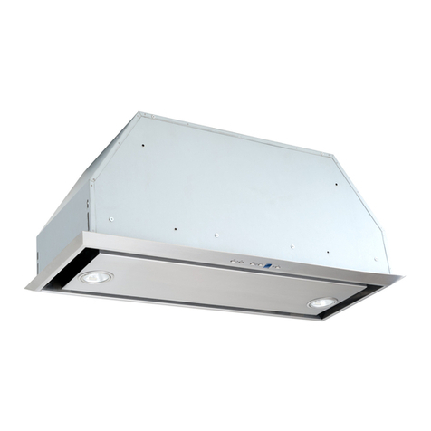
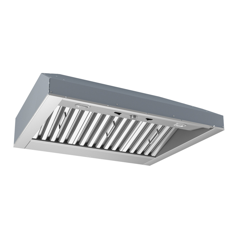
Best P195ES52SB User manual

- 1 -
ENGLISH.........................................3
FRANÇAIS......................................11
ESPAÑOL.......................................19
In USA - BEST Hartford, Wisconsin
InCANADA-BESTDrummondville,QC,Canada
REGISTER YOUR PRODUCT ONLINE AT : www.BestRangeHoods.com/register
For additional Information visit www.BestRangeHoods.com
Power Module
Module de Puissance
Módulo de potencia
Mod. P195ES52SB

- 2 -

- 3 -
READ AND SAVE THESE INSTRUCTIONS
WARNING
TO REDUCE THE RISK OF FIRE, ELECTRIC SHOCK, OR INJURY TO PERSONS,
OBSERVE THE FOLLOWING:
1. Usethisunitonlyinthemannerintendedbythemanufacturer.Ifyouhavequestions,
contactthemanufacturerattheaddress or telephonenumberlisted in thewarranty.
2. Before servicing or cleaning unit, switch power off at service panel and lock service
panel to prevent power from being switched on accidentally. When the service
disconnectingmeanscannotbelocked,securelyfastenaprominentwarningdevice,
suchasatag,totheservicepanel.
3. Installation work and electrical wiring must be done by a qualified person(s) in accor-
dancewith all applicable codesand standards, including fire-ratedconstructioncodes
andstandards.
4. Sufficientairis neededfor propercombustion andexhausting ofgasesthroughtheflue
(chimney)of fuelburningequipment toprevent backdrafting. Followthe heatingequip-
mentmanufacturer’sguidelinesand safety standards such as those published by the
National Fire Protection Association (NFPA), and the American Society for Heating,
RefrigerationandAirConditioningEngineers(ASHRAE), andthelocal codeauthorities.
5. When cutting or drilling into wall or ceiling, do not damage electrical wiring and other
hiddenutilities.
6. Ductedfansmust always be vented totheoutdoors.
7. Donotuse this unit withanyseparate solid-state speed controldevice.
8. Toreducetheriskof fire, use only metal ductwork.
9. Thisunitmust begrounded.
!
INTENDED FOR DOMESTIC COOKING ONLY
!

- 4 -
!
CAUTION
1. Forindooruseonly.
2. Toreduceriskof fireandto properlyexhaustair,besuretoductair outside.Donotvent
exhaustairintospaceswithin wallsor ceilingsorintoattics,crawlspaces,or garages.
3. Takecarewhen using cleaningagentsor detergents.
4. Avoidusingfood productsthatproduce flames underthe Range Hood.
5. Forgeneralventilatinguseonly. Donot useto exhausthazardousorexplosivemateri-
alsandvapors.
6. Toavoidmotor bearingdamageand noisyand/orunbalanced impellers, keepdrywall
spray,constructiondust, etc. off power unit.
7. Yourhoodmotor hasathermal overloadwhich willautomaticallyshut offthemotor ifit
becomesoverheated.Themotor willrestart whenit coolsdown. Ifthemotorcontinues
toshutoff and restart, have the hood serviced.
8. Forbestcapture ofcooking impurities,thebottom ofthehood shouldbe aminimumof
24"and a maximum of30"above the cooking surface.
9. Usewithapproved cord-connection kitonly.
10. Pleasereadspecificationlabel onproduct forfurther informationandrequirements.
WARNING
TO REDUCE THE RISK OF A RANGE TOP GREASE FIRE:
A. Never leave surface units unattended at high settings. Boilovers cause smoking and
greasyspillovers that mayignite.Heat oilsslowlyon low ormediumsettings.
B. Always turn hood ON when cooking at high heat or when cooking flaming foods. (i.e.
CrepesSuzette,CherriesJubilee, Peppercorn Beef Flambe’).
C. Cleanventilatingfansfrequently.Greaseshouldnot beallowedtoaccumulateon fanor
filter.
D. Use proper pan size. Always use cookware appropriate for the size of the surface
element.
TO REDUCE THE RISK OF INJURY TO PERSONS IN THE EVENT OF A RANGE TOP
GREASE FIRE, OBSERVE THE FOLLOWING:*
1. SMOTHERFLAMESwithaclose-fittinglid,cookie sheet,or metaltray, thenturn offthe
burner.BE CAREFULTOPREVENT BURNS.If the flamesdo notgoout immediately,
EVACUATEANDCALLTHEFIREDEPARTMENT.
2. NEVERPICKUP AFLAMINGPAN -You maybeburned.
3. DONOTUSE WATER,including wetdishcloths ortowels-violentsteam explosionwill
result.
4. Useanextinguisher ONLYif:
A. YouknowyouhaveaClassABC extinguisherandyou alreadyknowhowtooperate
it.
B. Thefireissmall and containedinthe area whereitstarted.
C. The firedepartmentisbeingcalled.
D. You can fight the firewithyourback to an exit.
*Based on “KitchenFire Safety Tips”publishedby NFPA.

- 5 -
PREPARE THE HOOD
Unpack hood and check contents.
1 - Hood
1 - Parts Bag (B08084044) containing:
4 - Mounting Screws (4,2 x 15mm Pan Head)
1 - 6” Damper
1 - Installation Instructions
DAMPER (B08088378)
4 MOUNTING SCREWS
(4,2 x 15mm Pan Head)
!
CAUTION
Wear safety gloves before every installation
and/ormanitenanceoperation

- 6 -
AIR
AIR
GRILL
6” ROUND
DUCT AND
ELBOW
DUCT
CONNECTOR
HOOD
At least
15”
INSTALL THE DUCTWORK (Ducted Hoods Only) -Fig.1
NOTE: To reduce the risk of fire, use only metal ductwork.
1. Decide where to install the duct.
The ducting from this fan to the outside of the building has a strong effect on the air
flow, noise and energy use of the fan. Use the shortest, straightest duct routing
possible for best performance, and avoid installing the fan with smaller ducts than
recommended. Insulation around the ducts can reduce energy loss and inhibit
mold growth. Fans installed with existing ducts may not achieve their rated airflow
2. Use duct tape to seal the joints between ductwork sections.
3. Install a roof or wall cap. Connect 6” round metal ductwork to cap and work back
towards hood location
DUCTED
CONFIGURATION ROOF CAP
6” ROUND
DUCT
WALL
CAP
HOOD
24” TO 30” ABOVE
COOKING SURFACE
6” ROUND
ELBOW
INSTALL DUCT CONNECTOR
1. Install the damper onto the hood by pressing it onto the discharge opening.
2. Remove the tape located on the damper.
Fig.1
Fig. 2
NON-DUCTED CONFIGURATION
INSTALL THE DUCTWORK (Non-Ducted Hoods Only) -Fig.2
NOTE: The following material must be purchased separately for non-ducted
recirculation installation.
•Non-ducted Charcoal Filter Model:
FILTEREB40
•6” round metal ductwork and fittings.
•Grill
1. Attach 6” round metal ductwork and fittings.
2. Run ductwork to the location where it is
discharged back into the room.
3. Duct tape all joints to make them secure and
air tight.
4. Install a decorative grill. You may need to
purchase a metal round-to-rectangular
transition, depending on your application.

- 7 -
INSTALL THE HOOD
Note:Thehoodmustbeinstalledinside
thecabinet.
The internal height of cabinet must be
minimum16”.
Thehoodshouldbemountedcentered
overthecooktopburners.
1. Removetheframebymovingthe2slide
fasteners“A”forward(Fig.4).Pushthe
filterlatchandtiltthefilterdownward(B)
and remove.
2. Cutaholeinthebottomofthecabinet,
using the dimensions shown (Fig.5 ).
3. Adjust the positionoftheclasping side
spring by turning the “D” screw
according to the thickness of the
cabinet to which it is going to be
anchored (Fig.6).
4. Insertthehoodinthecabinet(Fig.7)and
lockintopositionusingthesidespring.
5. Secure the hood with (4) “C” mounting
screws.
6.Replacetheframebymovingthe2slide
fasteners“A” backward. (Fig.4).
19-1/2
10-¼”
1”
Fig. 5
X= min 7/16”
max 13/16”
CLASPING SIDE
SPRING
X
Fig.6
D
Fig.7
CONNECT DUCTWORK
1. Use 6" round metal duct to connect
the duct connector on the hood to the
ductwork above.
2. Use duct tape to make all joints
secure and air tight.
Fig. 4
HOOD
33-7/16”
(85cm.)
MAX.
WIRING
Note:Thisrangehood must be properly
grounded.Theunitshouldbeinstalledby
a qualified electrician in accordance
with all applicable national and local
electricalcodes. The grounded 3 prong
outlet should be accessible after the
hoodinstallation (i.e.: access door).
GROUNDINGINSTRUCTIONS
This appliance must be grounded. In the
event of an electical short circuit,
grounding reduces the risk of electric
shockbyproviding an escape wireforthe
electriccurrent.Thisapplianceisequipped
withacordhavingagroundingwirewitha
groundingplug.Theplugmustbyplugged
intoanoutlet thatisproperlyinstalledand
grounded.
WARNING - Improper grounding can
resultina risk ofelectricshock.
Consult a qualified electrician if the
grounding instructions are not completely
understood, or if doubt exist as to wheter
theapplianceisproperlygrounded.Donot
useanextensioncord.Ifthepowersupply
cordistooshort,haveaqualifiedelectrician
installanoutletneartheappliance.Position
the power socket at a maximum distance
of 33-7/16” (85cm.) from where the lead
exits from the hood (see illustration
alongside). Fit the plug into the power
socket.

- 8 -
01 0123
INSTALL FILTERS
(NON-DUCTED HOODS ONLY - Fig.8 )
1. Install a charcoal filter on each side of
the blower (included with Non-ducted
Charcoal Filter Model: FILTEREB40
2. To install the charcoal filter, align center
keyhole slot on the filter with center of
theblower. Rotatetolockfilterintoplace.
3. To remove the charcoal filter, rotate the
filter until it disengages from the blower.
(DUCTEDAND NON-DUCTED HOODS)
•To remove the GREASE filter, grip the
latch tab and pull it down. This will
disengange the filter from the hood.
•To install the GREASE filter, align filter
tabs to the side of the filter with slots in
the hood drawer. Pull latch tab down,
push filter up into place and release the
tab.
•Make sure the filter is securely
enganged after assembly.
Fig.8
NON-DUCTED
RECIRCULATION FILTERS
MAINTENANCE
ALWAYS SWITCH OFF THE ELECTRICITY
SUPPLY BEFORE CARRYING OUT ANY
OPERATIONS ON THE APPLIANCE.
Grease Filters
The grease filter should be cleaned fre-
quently. Use a warm detergent solution.
Grease filter is dishwasher safe.
Toremovethe grease filter:pushinonthe
metallatchtab.Tiltthefilterdownwardand
remove.
Cleaning
Occasional care will help preserve its fine
appearance.
•Cleanwithwarmwaterandmilddetergent
only.
• Follow all cleaning by rinsing with clear
water.
•Wipe dry withclean,soft cloth.
Lightbulbs-(Fig.9)
Thisrangehoodrequirestwo13wattG24q-
1 Compact Fluorescent lamps (included).
To change bulbs:
1. Removetheframebymovingthe2slide
fasteners (A) (Fig.4, page 6).
2. To replace lamp, grasp lamp at
base and pull out to remove. Replace
with 13W Fluorescent lamp noted
above.
CAUTION: BULB MAY BE HOT!
Fig.9
OPERATION - Fig.10
Controls
Thelight switchturnsthelampsonand
off.
The blower switch: makes it possible
to select the motor operating speed (3
speeds).
Position 0: motor off.
The pilot lamp lights up whenever the
blower is on.
LIGHT
SWITCH BLOWER
SWITCH
PILOT LAMP Fig.10

- 9 -
WARRANTY
ONE YEAR LIMITED WARRANTY FOR BEST PRODUCTS
Broan-NuToneLLC (Broan-NuTone) warrantstothe original consumerpurchaser of
Bestproductsthat suchproductswillbefree fromdefectsinmaterialsorworkmanship
fora period of oneyearfrom the date of originalpurchase.THERE ARE NO OTHER
WARRANTIES, EXPRESS OR IMPLIED, INCLUDING, BUT NOT LIMITED TO,
IMPLIED WARRANTIES OR MERCHANT ABILITY OR FITNESS FOR A
PARTICULARPURPOSE.
Duringthisone-year period,Broan-NuTonewill,atits option,repairorreplace,without
charge, any product or part which is found to be defective under normal use and
service.
THISWARRANTY DOES NOT EXTEND TO FLUORESCENT LAMP STARTERS,
TUBES,HALOGENANDINCANDESCENTBULBS,FUSE,FILTERS,DUCTS,ROOF
CAPS,WALL CAPS AND OTHER ACCESSORIES FOR DUCTING. This warranty
does not cover (a) normal maintenance and service or (b) any products or parts
whichhavebeen subject to misuse, negligence, accident, impropermaintenanceor
repair (other than by Broan-NuTone), faulty installation or installation contrary to
recommendedinstallation instructions.
Theduration of anyimpliedwarranty is limited totheone-year period asspecifiedfor
the express warranty. Some states do not allow limitation on how long an implied
warranty lasts, so the above limitation may not apply to you.
BROAN-NUTONE'S OBLIGATION TO REPAIR OR REPLACE, AT BROAN-
NUTONE'S OPTION, SHALL BE THE PURCHASER'S SOLE AND EXCLUSIVE
REMEDYUNDERTHIS WARRANTY. BROAN-NUTONE SHALL NOT BE LIABLE
FOR INCIDENTAL, CONSEQUENTIAL OR SPECIAL DAMAGES ARISING OUT
OFORINCONNECTIONWITHPRODUCTUSEORPERFORMANCE.Somestates
donot allowthe exclusionor limitationofincidental orconsequential damages,so the
abovelimitationor exclusion may not apply to you.
This warranty gives you specific legal rights, and you may also have other rights,
which vary from state to state. This warranty supersedes all prior warranties.
To qualify for warranty service, you must (a) notify Broan-NuTone at the address
statedbelow or telephone number statedbelow,(b) give the modelnumberand part
identification and (c) describe the nature of any defect in the product or part. At the
time of requesting warranty service, you must present evidence of the original
purchasedate.
In USA - Best®, 926 W. State Street, Hartford, WI 53027 (800-558-1711)
In Canada - Best®, 550 Lemire Blvd., Drummondville, QC J2C 7W9
(866-737-7770)
www.BestRangeHoods.com
HEAT SENTRY™
Your hood is equipped with a HEAT SENTRY™ thermostat. This thermostat is a
devicethatwillturnonorspeeduptheblowerifitsensesexcessiveheatabovethe
cooking surface.
1)IfblowerisOFF-itturnsblowerONtoHIGHspeed.
2) If blower is ON at a lower speed setting - it turns blower up to HIGH speed.
When the temperature level drops to normal, the blower will return to its original
setting.
WARNING
TheHEATSENTRYthermostatcanstarttheblowerevenifthehoodisturned
OFF.Whenthisoccurs,itisimpossibletoturntheblowerOFFwithitsswitch.If
youmuststoptheblower,doitfromthemainelectrical panel.

- 10 -
SERVICE PARTS
B08093943
B03295083
B02011013
B08087694
B02300985
B02320351
B03293051
B02300787
B03294033
B02300983
B08088378
B03202287
B03290499
B03295084
B032920170
B032920180
BR2300132
B032920200
B03294781
B08086668
B02300987
B02320352
B08080375
B03201014
B03295075
B03295072
B03295074
B03295073
B08084044
B06002195
B06108783
FRAME
SIDE FASTENER
SPRING
GREASE FILTER
CAPACITOR
FLUORESCENT LAMP
LIGHT LENS
HEAT SENTRY
ELECTRICAL PRINTED CIRCUIT BOARD BOX COVER
POWER CORD
DAMPER
CABLE STOP
WIRE GUIDE
GRID LATCH
WIRING BOX
WIRING BOX COVER
JUNCTION CLAMP
ELECTRICAL BOX WIRE CLAMP
ELECTRICAL PRINTED CIRCUIT BOARD BOX
ELECTRICAL PRINTED CIRCUIT BOARD
FLUORESCENT LAMP HOLDER
FLUORESCENT BALLAST
SWITCH MOUNTING BOARD
PILOT LAMP
SWITCH BOARD BOX COVER
SWITCH BOARD BOX
MOTOR SWITCH
LIGHT SWITCH
PARTS BAG
BLOWER ASSEMBLY (Included Key No. 45, 48, 49, 53)
SWITCH BOX ASSEMBLY (Included Key No. 228, 229,
230, 234, 238, 241)
1
4
6
9
14
18
29
37
39
60
86
107
114
134
145
146
147
151
165
166
197
208
228
229
230
234
238
241
998
CAS
AQI
KEY No. PART No. DESCRIPTION

- 11 -
LISEZ ET CONSERVEZ CES INSTRUCTIONS
AVERTISSEMENTS
POUR REDUIRE LES RISQUES D’INCENDIE, DE DECHARGES ELECTRIQUES
OU DE DOMMAGES AUX PERSONNES, OBSERVEZ LES INSTRUCTIONS
SUIVANTES:
1. N’utilisez cet appareil que comme cela est indiqué par le constructeur. Si vous
avez des problèmes, contactez le fabriquant à l’adresse ou au numéro de
téléphone indiqués dans la garantie.
2. Avant de pourvoir à l’entretien ou au nettoyage de votre appareil, éteignez-le
au tableau des commandes ou bloquez le tableau des commandes afin d’éviter
de le mettre en marche accidentellement. Si vous ne pouvez pas bloquer le
système permettant d’éteindre votre appareil, appliquez un avertissement
extérieur d’une façon sure, comme par exemple un panneau, sur le tableau des
commandes.
3. L’assemblage et la connexion électrique doivent être faits par des personnes
qualifiées en respectant les normes et règlements en vigueur, y compris les
normes et règlements concernant les possibilités d’incendie.
4. Il est indispensable qu’il y ait suffisamment d’air pour que la combustion et
l’évacuation des gaz à travers le tuyau du brûleur du combustible ait lieu sans
retourdeflamme.Suivezlesindicationsdonnéesparlefabricantdubrûleurainsi
que les normes de sécurité comme celles qui sont publiées par l’Association
Nationale pour la Protection contre les Incendies National Fire Protection
Association (NFPA) et la American Society for Heating, Refrigeration and Air
Conditioning Engineers (ASHRAE), et les autorités locales en matière de
normes.
5. Quand vous coupez ou percez des trous dans le mur ou le plafond, n’abîmez
pas les fils électriques ou autres.
6. Le ventilateur canalisé doit toujours évacuer l’air vers l’extérieur.
7. N’utilisez pas cet appareil avec un appareil contrôlant la vitesse à état solide.
8. Afin de diminuer tout risque d’incendie n’utilisez que des conduits en métal.
9. Votre appareil doit être relié à la terre.
SEULEMENT POUR UTILISATION DOMESTIQUE
! !

- 12 -
ATTENTION
1. Pour usage intérieur seulement.
2. Pourréduiretoutrisque d’incendieet pourévacuercorrectementl’air,assurez-vous de
prévoirun conduit de ventilationextérieur.Ne videz pas l’air danslesespaces limités
pardesmurs ou des plafonds, les combles, lespassagesétroitsou les garages.
3. Faitestrèsattention quandvous utilisez desproduits denettoyageou desdétergents.
4. Évitezd’utiliserdes alimentspouvant s’enflammersous laRangeHood.
5. N’utilisezcetappareilquepouruneventilationgénérale.Nel’utilisezpaspourévacuer
desmatières ou des vapeursdangereusesou qui peuvent exploser.
6. Pouréviterde causerdes dommagesaumoteur etde rendrelesrotors bruyantset/ou
non équilibrés, évitez que les sprays pour murs secs, la poussière de construction
entrenten contact aveclapartie électrique.
7. Lemoteurdevotrehotteaunthermostatquiéteindraautomatiquementlemoteurs’ilest
surchauffé. Le moteur se remettra en marche lorsqu’il se sera refroidi. Si le moteur
continueà s’éteindre et àseremettre en marche,faitesvérifier votre hotte.
8. Pourmieuxcapturer les impuretés de cuisine,lebas de votre hottedevraitêtreà une
distance minimum de 24” et à une distance maximum de 30” au-dessus du plan de
cuisson.
9. Utiliseruniquementavec un kit deconnexionpour alimentation homologué.
10. Nous vous recommandons de lire l’étiquette indiquant les caractéristiques de votre
hottepour deplusamples informations et exigences.
AVERTISSEMENTS
POUR REDUIRE LES RISQUES D’INCENDIE DES MATIERES GRASSES QUI SONT
EN TRAIN DE CUIRE:
A. Ne laissez jamais ni vos éléments chauffants, ni vos casseroles ou poêles sur le feu
sans les contrôler si vous réglez l’apport de chaleur sur une position élevée. Si vos
casserolesoupoêles débordent cela provoque de la vapeur etdeséclaboussuresde
graissequi peuvent prendrefeu. Chauffez leshuiles lentement àfeubas oumoyen.
B. Faitestoujoursfonctionnervotre hotte quandvous cuisez àdestempératures élevées
ou quand vous cuisinez des plats flambés. (par ex. crêpes Suzette, Cerises “Jubilé”,
Steackau poivreflambé).
C. Nettoyez régulièrement lesailesdevos ventilateurs. Ne permettezpasque la graisse
s’accumulesur le ventilateurousur le filtre.
D. Utilisez descasserolesde tailleappropriée. Utiliseztoujoursdes ustensilesdecuisson
dontla taille estappropriéeà la surfacede votre élémentdecuisson.
POUR REDUIRE LES RISQUES DE DOMMAGES AUX PERSONNES AU CAS OÙ
VOTRECUISINIEREPRENDRAITFEU,OBSERVEZLESINSTRUCTIONS SUIVANTES:*
1. ETEINDRE LES FLAMMES à l’aide d’un couvercle le plus hermétique possible, une
plaqueà gâteaux, ou un plateau en métal,puiséteindre le brûleur. ATTENTION à NE
PASVOUS BRÛLER.Si lesflammes nes’éteignentpas immédiatement,SORTEZ ET
APPELEZLESPOMPIERS.
2. NEPRENEZJAMAISEN MAINUNEPOÊLEOUUNE CASSEROLEQUIAPRISFEU
-Vouspourriezvous brûler.
3. N’UTILISEZPASD’EAU,ni torchonsouserviettesmouillés - vous provoqueriez une
violenteexplosiondevapeur.
4. UtilisezunextincteurSEULEMENTsi:
A. Voussavezque vousavez unextincteur ClasseABC, etvous enconnaissez déjàle
moded’emploi.
B. Cen’estpasun très grosincendie et qu’ilselimite à l’endroioùil a explosé.
C. Vous êtes entraind’avertir les pompiers.
D. Vous avez la possibilitéd’essayerd’éteindre l’incendie en ayant le dostournévers
uneissue.
* D’après les “Suggestions concernant la Sécurité contre les incendies des cuisines”
publiéesparNFPA.
!

- 13 -
PRÉPARATION DE LA HOTTE
Retirer la hotte de l’emballage, puis vérifier le contenu.
1 - Hotte
1 - Sac de pièces (B08084044) comprenant:
4 - Vis de montage (4,2 x 15mm Tête ronde)
1 - Clapet de 6 Po
1 - Directives d’installation
CLAPET (B08088378)
4 VIS DE MONTAGE
(4,2 x 15mm tête ronde)
ATTENTION
Mettre gants de protection avant d’ installer ou
effectuerunemanitenance
!

- 14 -
AIR
AIR
GRILLE
TUYAURONDET
COUDE ROND
DE 6 Po
CONNECTEUR
MODULE DE
Au moins
15 Po
PUISSANCE
DE CONDUIT
INSTALLATION DU SYSTEME D’EVACUATION
(HOTTESCANALISÉESUNIQUEMENT)-Fig.1
REMARQUE:Pour réduire lesrisquesd’incendie, n’utilisez quedes tuyaux enmétal.
1. Décidez où le tuyau rond doit être installé.
Les conduits allant de ce ventilateur jusqu’à l’extérieur de l’habitation ont
une grande influence sur le débit d’air, le bruit du ventilateur et sa
consommation d’énergie. Pour obtenir le meilleur rendement, utilisez les
conduits les plus courts et les plus droits que possible et évitez d’utiliser
des conduits plus petits que ceux recommandés. L’isolation des conduits
peut contribuer à réduire les pertes d’énergie et éviter la prolifération de
moisissures. Les ventilateurs installés sur d’anciens conduits pourraient ne
pas produire leur
débit d’air nominal.
2. Utilisez du ruban
adhésif pour sceller
les joints entre les
sections de conduits.
3. Installez un couvercle
de toit ou au mur.
Reliezuntuyaude6Po
en métal rond au
couvercle, puis retour
vers emplacement de
la hotte.
COUVERCLE DU TOIT
TUYAU ROND
DE 6 PO
COUVERCLE
DU MUR
MODULE DE
PUISSANCE
DE 24”(61cm) À 30”
(76cm) AU-DESSUS
DU PLAN DE
CUISSON
COUDE ROND DE 6 PO
CONNEXION DU SYSTEME D’EVACUATION
1. Installez le clapet sur la hotte en appuyant sur l’ouverture de décharge.
2. Retirez le ruban adhésif situé sur le clapet.
Fig.1
Fig. 2
NON-CANALISÉS CONFIGURATION
INSTALLER LES CONDUITS
(Hottes non canalisés uniquement) - Fig.2
NOTE: Le matériel suivant doit être acheté séparément pour l’installation de
recirculation non canalisés.
•Filtre à charbon pour hotte non-canalisé
Modele: FILTEREB40
•Conduit rond en metal de 6 PO et les
raccords
•Grille
1. Attachez un tuyau rond en metal de 6 Po et
les raccords.
2. Installez les conduits à l’endroit où il est
évacué dans la cuisine.
3. Le ruban adhésif tous les joints pour les
rendre sécuritaires et hermétiques.
4. Installer une grille décorative. Vous devrez
peut-être acheter un rond en métal à
rectangulaire de transition, en fonction de
votre demande.
HOTTE
CANALISE

- 15 -
INSTALLATION DE LA HOTTE
REMARQUE:lahottedoitêtreinstallée
àl’intérieurdumeuble.
L’hauteurintérieuredumeubledoitêtre
de16” (406.4mm) minimum.
Lahotte doit être montéeau milieu sur
lesfeuesduplandecuisson.
Fig. 4
19-1/2
10-¼”
1”
Fig. 5
X= min 7/16”
max 13/16”
X
Fig.6
D
Fig.7
DECOUPEZ UN TROU AU FOND DU MEUBLE
HOOD
33-7/16”
(85cm.)
MAX.
INSTALLATION ELECTRIQUE
Remarque: Ce modèle de hotte doit
êtrerelié à la terre correctement. Cet
articledevrait être installé par un
électricienqualifié selon les lois
nationales et localesen matière
d’électricité. La prise à 3 broches doit
être accessible après l’installation de
lahotte (parexemple: laporte d’accès).
INSTRUCTIONS POUR LA MISE A LA
TERRE
Cet appareil doit être relié à la terre.
En cas de court-circuit, la mise à la terre
réduit le risque de décharge électrique
enfournissant un câble permettant au
courantd’être dévié. Cet appareil est
équipéd’uncordonayantuncâbledemise
àlaterreavecune fiche de mise àlaterre.
Lafichedoitêtrebranchéedansuneprise
decourant correctement installée et mise
àlaterre.ATTENTION-Unemiseàlaterre
incorrecte peut entraîner un risque de
décharge électrique.
Consulter un électricien spécialisé si les
instructionsde mise àla terre nesont pas
tout à fait compréhensibles ou en cas de
doute sur le fait de savoir si l’appareil est
correctementreliéàlaterre.Nepasutiliser
de prolongation.
Si le cordon d’alimentation est trop court,
demanderàunélectricienagrééd’installer
une prise de courant près de l’appareil.
Régler l’alimentation électrique dans
l’espace couvert par le conduit décoratif.
Placer la prise femelle à une distance
maximumde33-7/16”(85cm)del’endroit
oùleplombsortdelahotte(voirl’illustration
ci-contre). S’assurer qu’il n’y ait pas
d’interférence avec la zone de fixation du
support ou avec le conduit décoratif
(àl’endroit où la gaine touche le mur).
Mettre la fiche dans la prise femelle.
1.Otezlagrilleendéplaçantlesdeuxattacheslatérales‘’A’’(Fig.4).Presserlapoignée
des filtres et faites basculer les filtres vers le bas (B) et les retirer.
2.Découpezuntrouaufonddumeubleenutilisantlesdimensionsreportéesdanslafig.5.
3.Réglezlapositionduressortdefixationlatéralàl’aidedelavis‘’D’’correspondanteet
ce,enfonctiondel’épaisseurdupanneaudécoupéquiserviradesupportpourlafixation
(Fig.6).
4.Placerlahottedanslemeuble(Fig.7)etverrouillezàl’aideduressortlatéral.
5.Fixerlahotteàl’aide(4)desvis“C”demontagepourtôle.
6.Reposez la grilleavec les deuxattaches latérales ‘’A’’(Fig.4 ).

- 16 -
INSTALLER LES FILTRES
(Hottesnon-canalisées
uniquement - Fig.8 )
1. Installez un filtre à charbon de
chaque côté du ventilateur (inclus
avec le modèle “Non-canalisé -
Filtre à charbon”: FILTEREB40
2. Pour installer le filtre à charbon,
alignez le centre fente en trou de
serrure sur le filtre avec le centre
de la soufflerie. Tourner pour
verrouiller en position.
3. Pour retirer le filtre à charbon,
tourner le filtre jusqu’à ce qu’il se
dégage de la soufflerie.
(Hottescanaliséeset
non-canaliséesuniquement)
•Pour enlever les filtres à graisse
poussez sur la languette. Faites
basculer les filtres vers le bas et
les retirer. Cela disengange le filtre
de la hotte.
•Pour installer le filtre à graisse,
aligner les onglets de filtre du côté
du filtre à fentes dans le tiroir hotte.
Tirez verrouiller onglet vers le bas,
pousser le filtre en place en place
et relâchez la languette.
•Assurez-vous que le filtre est bien
enganged après assemblage.
Fig.8
ENTRETIEN
TOUJOURS COUPER L’ALIMENTATION
ELECTRIQUE AVANT D’EFFECTUER
UNE QUELCONQUE OPERATION SUR
L’APPAREIL.
Filtreàgraisse
Les filtres à graisse devront être
fréquemment nettoyés. Utilisez une
solution détergente chaude. Les filtres
à graisse peuvent être lavés en
machine.
Pourenleverlesfiltresàgraissepoussez
sur la languette du verrou métallique.
Faites basculer les filtres vers le bas et
les retirer.
Nettoyage
Un entretien ponctuel contribuera à
préserver son aspect.
• Nettoyez à l’eau chaude en prenant
soin d’utiliser un détergent non
agressif.
• Faites suivre le nettoyage d’un rinçage
à l’eau claire.
•Essuyezavecunchiffonpropreetdoux.
Ampoules (Fig.9)
Ce type de hotte nécessite deux lampes
fluorescentes à 13 watt G24q-1
(comprises)
Pourchangerleslampesfluorescentes:
1.Otezlagrilleenenlevantles2attaches
latérales (A).
2.Pour remplacer les lampes
fluorescentes,saisirlalampeàlabaseet
tirer pour enlever. Remplacez avec
lampes fluorescentes 13W.
ATTENTION: L’AMPOULE PEUT
ÊTRE CHAUDE.
Non-canalisé
Filtre à charbon
FONCTIONNEMENT - Fig.10
Commandes
L’interrupteur de la lumière allume et
éteint les lampes.
L’interrupteur du moteur permet de
sélectionner la vitesse de marche du
moteur. Position 0: moteur éteint.
Le voyant lumineux s’allume quand le
moteur fonctionne.
01 0123
INTERRUPTEUR
LUMIERE
VOYANT LUMINEUX Fig.10
INTERRUPTEUR
MOTEUR
Fig.9
RACCORDEMENTDUCONDUIT
1. Utilisezun conduitrondenmétalde
6Popourrelierleraccorddeconduit
sur la hotte au conduit au-dessus.
2. Sceller hermétiquement les joints à
l’aide de ruban à conduits.

- 17 -
DÉTECTEUR DE CHALEUR HEAT SENTRY™
Votrehotteestmunied'undétecteurdechaleurHEATSENTRY™.Ils’agitd’un dispositif
quiactionnera ouaugmenteralavitesse duventilateurs’l détecte unechaleurexcessive
au-dessu de la surface de cuisson.
1)Sileventilateurn’estPASENMARCHE,il actionnera le ventilateur à haute vitesse.
2)SileventilateurestENMARCHEàbassevitesse,leventilateurpasseraàhautevitesse.
Lorsquelatempératurerevientàlanormale,leventilateurretourneàsavitessed’origine.
AVERTISSEMENT
Le thermostat HEAT SENTRY peut activer la soufflante même si la hotte est
ÉTEINTE. Dans ce cas, il est impossible de DÉSACTIVER la soufflante avec le
commutateurd'arrêt.Sivousdevezarrêterlasoufflante,faites-ledepuislepanneau
électrique principal.
GARANTIE
GARANTIE LIMITÉE DE UN AN DE BEST
Broan-NuToneLLC(Broan-NuTone)garantitàl'acheteuroriginalquelesproduitsBEST
vendusenvertudelaprésentesontlibresdetoutvicedematériauoudefabricationpour
une période de un an à compter de la date d'achat originale. CETTE GARANTIE NE
COMPORTE AUCUNE AUTRE GARANTIE, EXPRESSE OU TACITE, Y COMPRIS,
MAISSANSS'YLIMITER,LESGARANTIESTACITESDEVALEURMARCHANDEOU
D'ADAPTATIONÀUNUSAGEPARTICULIER.
Durantcettepériodedeunan,Broan-NuTonerépareraouremplaceragratuitement,àsa
discrétion, tout produit ou toute pièce jugés défectueux dans des conditions normales
d'utilisation.
CETTE GARANTIE NE S'APPLIQUE PAS AUX TUBES FLUORESCENTS ET AUX
STARTERS,NIAUXAMPOULESHALOGÈNESOUINCANDESCENTES,FUSIBLE,
FILTRES, CONDUITES, CHAPEAUX DE TOIT, CHAPEAUX DE MUR ET AUTRES
ACCESSOIRES POUR CANALISATIONS. Cette garantie ne couvre pas (a) les frais
d'entretienoudeservicenormauxni(b)toutproduitoutoutepiècesoumisàuneutilisation
inadéquate,unenégligence,unaccident,unentretienouuneréparationinadéquats(autres
queceuxeffectuésparBroan-NuTone),unemauvaiseinstallationouuneinstallationcontraire
aux instructionsrecommandées.
Laduréedetoutegarantietaciteestlimitéeàlapériodedeunanstipuléepourlagarantie
expresse.CertainsÉtatsouprovincesnepermettentpasdelimitesquantàladuréed’une
garantieimplicite.La restrictionsusmentionnéepeutdoncnepass'appliquerdansvotre
cas.
BROAN-NUTONE’SL'OBLIGATIONPOURBROAN-NUTONEDERÉPAREROUDE
REMPLACERLEPRODUIT,ÀSADISCRÉTION,CONSTITUELESEULRECOURSDE
L'ACHETEUR EN VERTU DE CETTE GARANTIE. BROAN-NUTONE NE PEUT PAS
ÊTRETENUERESPONSABLEDETOUTDOMMAGEINDIRECT,CONSÉCUTIFOU
ACCESSOIREDÉCOULANTDEL'UTILISATIONOUDURENDEMENTDUPRODUIT.
CertainsÉtatsouprovincesinterdisentl'exclusionoularestrictiondesdommagesindirects
ouconsécutifs.Larestrictionsusmentionnéepeutdoncnepass'appliquerdansvotrecas.
La présente garantie vous confère des droits spécifiques reconnus par la loi. D'autres
droitspourraientégalementvousêtreaccordésselonlalégislationlocaleenvigueur.La
présentegarantieremplacetouteslesautresgarantiesprécédentes.
Pourleservicesousgarantie,vousdevez(a)aviserBroan-NuToneàl'unedesadresses
ounuméros de téléphonementionnésci-dessous, (b) indiquer lenumérode modèle et
d'identificationdelapièceet(c)décrireladéfectuositéduproduitoudelapièce.Lorsd’une
réclamation,vousdevezprésenterunepreuvedeladate d'achatoriginale.
In USA - Best®, 926 W. State Street, Hartford, WI 53027 (800-558-1711)
In Canada - Best®, 550 Lemire Blvd., Drummondville, QC J2C 7W9
(866-737-7770)
www.BestRangeHoods.com

- 18 -
LISTE DES PIÈCES DE RECHANGE
B08093943
B03295083
B02011013
B08087694
B02300985
B02320351
B03293051
B02300787
B03294033
B02300983
B08088378
B03202287
B03290499
B03295084
B032920170
B032920180
BR2300132
B032920200
B03294781
B08086668
B02300987
B02320352
B08080375
B03201014
B03295075
B03295072
B03295074
B03295073
B08084044
B06002195
B06108783
ENCADREMENT
ARRET DE GRILLE
RESSORT
FILTRE Á GRAISSE
CONDENSATEUR
TUBE AU NEON
PLAFFONIERE
HEAT SENTRY
COUVERCLE BOITE CIRCUIT IMPRIME ELECTRIQUE
CABLE ALIMENTATION
BRIDE DE RACCORDEMENT
ARRET CABLE
SERRE CABLE
CROCHET
BOITE CABLE ALIMENTATION
COUVERCLE BOITE CABLE ALIMENTATION
BORNE
SERRE CABLE BOITE INSTALLATION ELECTRIQUE
BOITE INSTALLATION ELECTRIQUE
CIRCUIT IMPRIME ELECTRIQUE
SUPPORT NEON
RÉGULATEUR DE COURANT
CIRCUITE IMPRIME COMMANDES
LAMPE TEMOIN
COUVERCLE TABLEAU DE COMMANDES
BOITE TABLEAU DE COMMANDES
BOUTON MOTEUR
BOUTON LUMIERE
ACCESSOIRE DE FIXATION
ENSEMBLE CONVOYER (Comprend les repères n°. 45,
48, 49, 53)
ENSEMBLE TABLEAU DE COMMANDES (Comprend les
repères n°. 228, 229, 230, 234, 238, 241)
1
4
6
9
14
18
29
37
39
60
86
107
114
134
145
146
147
151
165
166
197
208
228
229
230
234
238
241
998
CAS
AQI
N°
REPÈRE DESCRIPTION
N° DE
PIÈCE

- 19 -
LEA Y CONSERVE ESTAS INSTRUCCIONES
ADVERTENCIA
PARA EVITAR EL RIESGO DE INCENDIO, CORTOCIRCUITO O DAÑO PARA LAS
PERSONAS,OBSERVE ATENTAMENTE LASSIGUIENTES NORMAS:
1. Use esta unidad solamente de la manera indicada por el fabricante; si tiene dudas,
póngaseen contacto conéste a ladireccióno teléfono indicadosen la garantía.
2. Antesdehaceruna revisión o de limpiar la unidad, desconéctela de la redparaevitar
queseencienda de manera accidental. En el caso de que éste nopuedaserdesacti-
vado,se indicará nelpanelde servicio.
3. Elmontajey la instalación eléctricadebe hacerlos un técnicoespecializadosiguiendo
lasnormas estándareincluyendo aquellasdeconstrucción antiincendio.
4. Necesitaairesuficientepara unaapropiadacombustiónyescape degasesatravésdel
tubodeldepósitodequemadecombustible.Paraevitarqueelhumoaspiradovuelvaa
lacocina,siga lasdirectivas delfabricanteylasnormas estándarde siguridadasícomo
lasnormaspublicadasporlaAsociación deprevenciónde incendios(NFPA)ylaSocie-
dadamericanadeespecialistasencale-facción,refrigeracióny aire acondicionado y
ademáslas normas delas autoridades locales.
5. Hacer un corte o un taladro en la pared o en el techo no debe dañar la instalación
eléctricau otras instalacionesocultasen la pared.
6. Losconductosventiladores debensiempredesalojar alexterior.
7. Nouseesta unidad condispositivode controldela velocidad aestadosólido.
8. Paraevitarel riesgodeincendio, usesolamenteconductos demetal.
9. Estaunidadtiene que serconectadaa tierra.
INDICADOPARA ELUSO ENCOCINAS DOMESTICAS
!
!

- 20 -
PARA EVITAR EL RIESGO DE DAÑOS A PERSONAS EN CASO DE FUEGO POR
ALTO NÍVEL DE GRASA, TENGA EN CUENTA LO SIGUIENTE:*
1.SOFOQUE LALLAMAcon unatapaderaapropiada,unabandejametálicaóunutensilio
de cocína que pueda cubrirla, despues, apague el quemador. ACTÚE CON
PRECAUCÍON PARA EVITAR QUEMADURAS. Si la llama no se extingue inmedia-
tamente,SALGAYLLAMEALOSBOMBEROS.
2.NUNCA COJAUNASARTEN ENLLAMAS,porque correel riesgo dequemarse.
3. NO USE AGUA ni paños o toallas húmidas porque puede provocarse una violenta
humareda.
4.Use unextintorSOLAMENTE si:
A. Poseeunextintorde clase ABC ysabeperfectamente cómo usarlo.
B. Elfuegoespequeño yestácontrolado enelmismo sitio enque empezó.
C. Ha llamadoconanterioridad alos bomberos.
D. Puedecombatir elfuegoretrocedíendohacialasalida.
*Basado en“Seguridad antifuegoenla cocína”publicado porNFPA.
ADVERTENCIA
PARA EVITAR EL RIESGO DE FUEGO POR ALTO NIVEL DE GRASA:
A. Nuncaabandonelos quemadoresconel fuegoalto.La coccióncausa humoyrestos
degrasa quepueden arder.Calienteel aceitea fuegomedioo bajo.
B. Enciendasiemprelacampanacuandococineafuego altoocuandococinealimentos
fácilmente inflamables. (por ejemplo Crepes Suzette, Cerezas Jubilee, Ternera
flambeadacongranosdepimienta).
C. Limpie confrecuencialosventiladores.Nosedebe acumulargrasa enel ventiladoro
enelfiltro.
D. Usa el tamañpde cazuela apropiado.Usesiempre utensilios decocinade tamaño y
materialadecuados.
ADVERTENCIA
1. Parausoen interiores.
2. Parareducirelriesgodeincendiosyparaevacuarcorrectamenteloshumos,asegurarse
dehaberrealizado unaconducción delairehastaelexterior. Noexpulsar loshumosen
espacioscerradospor paredes o techos, áticos, espacios angostos o garajes.
3. Prestarlamáxima atenciónal utilizarproductosde limpiezaodetergentes.
4. Evitareluso deproductos alimentariosquepuedaninflamarsebajo lacampana.
5. Sóloparaventilación total.No usegasesde escapepeligrosos omaterialesy vapores
explosivos.
6. Paraevitardaños en el funcionamiento del motor eimpulsoresruidosos y/o desequi-
librados,mantengaalejadosdelaunidaddeencendidopulverizadoresensecoopolvo.
7. El motor tiene un nivel de sobrecarga térmica que apaga automáticamente el motor
cuandoseharecalentadoexcesivamente. Elmotorseponedenuevoenfincionamento
cuandola temperaturabaja. Sielmotor comienzaa encenderseya apagarse,deberá
haceruna revisión de éste.
8. Para limpiar mejor las impurezas al cocinar, la distancia entre la parte inferior de la
campanay la zona de cocción debe sermínimo24” - maximo 30”.
9. Usesolamentecon juego de conexión para alimentaciónaprobado.
10.Se recomienda leerla placa decaracteristicas del productopara ulterior información.
!
Table of contents
Languages:
Other Best Ventilation Hood manuals
Popular Ventilation Hood manuals by other brands

M-system
M-system MOK620WT manual

Fisher & Paykel
Fisher & Paykel HP60IDCHX3 INSTALLATION GUIDE/USER GUIDE

Baumatic
Baumatic BXX90SS instruction manual

Leisure
Leisure H91PK User instructions

Klimawent
Klimawent ERGO-MINI Use and maintenance manual

Kitchenware
Kitchenware RIV3CL9G Installation and operating instructions

Franke
Franke FTU 3807 Instructions for use and installation

Kleenmaid
Kleenmaid RH90 Instructions for use

AEG Electrolux
AEG Electrolux DF7460 OPERATING AND INSTALLATION Manual

ETNA
ETNA 4325TWT Instruction on mounting and use

Faber
Faber Stilux 90 instruction manual

Küppersbusch
Küppersbusch LB6700.0E Instructions for use and installation instructions