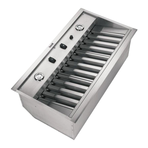
Best P195P2M70SB User manual

- 1 -
Model P195P
ENGLISH.......................................2
FRANÇAIS..................................11
ESPAÑOL...................................20
In USA - BEST Hartford, Wisconsin
InCANADA-BESTDrummondville,QC,Canada
REGISTER YOUR PRODUCT ONLINE AT : www.BestRangeHoods.com/register
For additional Information visit www.BestRangeHoods.com

- 2 -
READ AND SAVE THESE INSTRUCTIONS
WARNING
TO REDUCE THE RISK OF FIRE, ELECTRIC SHOCK, OR INJURY TO PERSONS,
OBSERVE THE FOLLOWING:
1. Usethisunitonly inthe mannerintended bythe manufacturer.If youhave questions,
contactthe manufacturerat theaddressor telephonenumberlisted inthe warranty.
2. Before servicing or cleaning unit, switch power off at service panel and lock service
panel to prevent power from being switched on accidentally. When the service
disconnectingmeans cannotbe locked,securelyfastenaprominentwarningdevice,
suchas atag, tothe servicepanel.
3. Installation work and electrical wiring must be done by a qualified person(s) in accor-
dancewith allapplicable codesandstandards, includingfire-rated constructioncodes
andstandards.
4. Sufficientair isneededfor propercombustionand exhaustingofgasesthrough theflue
(chimney)of fuelburningequipment topreventbackdrafting. Followtheheating equip-
mentmanufacturer’s guidelinesand safetystandards suchas thosepublished bythe
National Fire Protection Association (NFPA), and the American Society for Heating,
RefrigerationandAir ConditioningEngineers(ASHRAE),andthe localcodeauthorities.
5. When cutting or drilling into wall or ceiling, do not damage electrical wiring and other
hiddenutilities.
6. Ductedfans mustalways bevented totheoutdoors.
7. Donot usethis unitwith anyseparatesolid-state speedcontrol device.
8. Toreduce therisk offire, useonly metalductwork.
9. Thisunit mustbegrounded.
TOREDUCE THERISKOF ARANGE TOPGREASEFIRE:
A. Never leave surface units unattended at high settings. Boilovers cause smoking and
greasyspillovers thatmayignite. Heatoils slowlyonlow ormediumsettings.
B. Always turn hood ON when cooking at high heat or when cooking flaming foods. (i.e.
CrepesSuzette, CherriesJubilee, PeppercornBeef Flambe’).
C. Cleanventilatingfansfrequently. Greaseshouldnotbe allowedtoaccumulateon fanor
filter.
D. Use proper pan size. Always use cookware appropriate for the size of the surface
element.
WARNING
TOREDUCE THERISK OFINJURY TOPERSONS INTHEEVENT OFA RANGETOP
GREASEFIRE,OBSERVE THEFOLLOWING:*
1. SMOTHERFLAMES withaclose-fitting lid,cookiesheet,or metaltray,then turnoffthe
burner.BE CAREFULTOPREVENT BURNS.Ifthe flamesdonot gooutimmediately,
EVACUATEANDCALL THEFIREDEPARTMENT.
2. NEVERPICK UPAFLAMING PAN-Youmaybeburned.
3. DONOT USEWATER,including wetdishclothsor towels-violent steamexplosionwill
result.
4. Usean extinguisherONLY if:
A. Youknowyou haveaClassABCextinguisher andyoualreadyknowhow tooperate
it.
B. Thefire issmalland containedinthe areawhere itstarted.
C. Thefiredepartmentis beingcalled.
D. You canfight thefirewith yourback toan exit.
*Based on“KitchenFire SafetyTips” publishedbyNFPA.
!
INTENDED FOR DOMESTIC COOKING ONLY
!

- 3 -
!
CAUTION
1. Forindoor useonly.
2. Toreduceriskoffire andtoproperlyexhaustair, besuretoduct airoutside.Donotvent
exhaustairinto spaceswithinwallsorceilingsorinto attics,crawlspaces,or garages.
3. Takecare whenusing cleaningagentsor detergents.
4. Avoidusing foodproducts thatproduceflames undertheRange Hood.
5. Forgeneral ventilatinguseonly. Donotuse toexhausthazardousor explosivemateri-
alsand vapors.
6. Toavoid motorbearing damageandnoisy and/orunbalancedimpellers, keepdrywall
spray,construction dust,etc. offpower unit.
7. Yourhood motorhasa thermaloverloadwhich willautomaticallyshut offthemotorifit
becomesoverheated. Themotorwillrestart whenitcools down.Ifthe motorcontinues
toshut offand restart,have thehood serviced.
8. Forbest captureofcooking impurities,thebottom ofthehood shouldbea minimumof
24"and amaximum of30"above thecooking surface.
9. Thisproductis equippedwith athermostat whichmay startblower automatically.To
reduce the risk of injury and to prevent power from being switched on accidentally,
switchpower offat servicepanel andlock ortag servicepanel.
10. Usewithapproved cord-connectionkit only.
11. Pleasereadspecificationlabelonproduct forfurtherinformation andrequirements.

- 4 -
PREPARE THE HOOD
Unpack hood and check contents.
1 - Hood
1 - Hardware Bag (B08084041) containing:
4 - Mounting Screws (4,2 x 20 mm Pan Head)
1 - Parts Bag (B08084042) containing:
1 - Junction Box
1 - Junction Box Cover
2 - Cover Screws (3,9 x 6 Flat Head)
4 - Washer
2 - Mounting Screws (3,9 x 9,5mm Pan Head)
1 - Parts Bag (B080814051) containing:
1 - 6” Damper Duct Connector
2 - Mounting Screws (3,9 x 9,5mm Pan Head)
1 - Parts Bag (B080810849 - P195P2M70 ONLY) containing:
1 - 8” Damper Duct Connector
4 - Mounting Screws (3,9 x 9,5mm Pan Head)
1 - Installation Instructions
4 + 4 MOUNTING
SCREWS
(3,9 x 9,5mm Pan Head)
8” DUCT CONNECTOR
(B080810849 - P195P2M70 ONLY)
4 MOUNTING SCREWS
(4,2 x 20 mm Pan Head)
4 WASHER Ø4,3mm
1 JUNCTION BOX
1 JUNCTION BOX COVER
2 COVER SCREWS
(3,9 x 6mm Flat Head)
6” DUCT CONNECTOR
(B080814051)

- 5 -
INSTALL THE DUCTWORK
NOTE: To reduce the risk of fire, use only
metal ductwork.
1. Decide where to install the duct.
2. A straight, short duct will allow the hood to
perform most efficiently.
3. Long duct, elbows, and transitions will
reduce the performance of the hood. Use
as few of them as possible.
4. Use duct tape to seal the joints between
ductwork sections.
Ductedconfiguration(showninFig.1a):
Installarooforwallcap.Connecttheroundmetal
ductwork to cap and work back towards hood
location.
Non-Ductedconfiguration(showninFig.1b):
Install a decorative grill (not supplied by Best).
You may need to purchase a metal round-to-
rectangular transition depending on your
application.
DUCTED CONFIGURATION
ROOF CAP
ROUND
DUCT
WALL
CAP
HOOD
24” TO 30” ABOVE
COOKING SURFACE
ROUND
ELBOW
INSTALL JUNCTION BOXE
In the area marked “120 VAC INPUT”, place
a junction box on the top of the hood. Run the
wires through the hole below and secure with
(2) 3,9 x9,5 screws and (2) washers. See
Fig.3-4.
MOUNTING SCREWS
(3.9x9.5mm)
REMOVE THE TAPE
INSTALL DUCT CONNECTOR
1. Install the damper duct connector onto the
hood using mounting screws (3,9x9,5mm)
as shown in Fig.2
2. Remove the tape located on the damper.
See Fig.2.
Fig.1a
Fig.2
Fig.3
Fig.4
Fig.1b
NON-DUCTED CONFIGURATION
REMOVE THE TAPE
MOUNTING SCREWS
(3.9x9.5mm)
Model:
P195P1M52 - P195P1M70
(6” DUCT CONNECTOR)
Model:
P195P2M70
(8” DUCT CONNECTOR)
MOUNTING SCREWS
(3,9 x 9,5mm)
P195PM70Models
MARKED
“120 VAC INPUT”
MOUNTING SCREWS
(3,9 x 9,5mm) MARKED
“120 VAC INPUT”
P195P1M52Model

- 6 -
X
10 ¼”
1”
X=19-½” For Version P195P1M52
X=26- ” For Version P195PM70 Models
5/8
INSTALL THE HOOD
1. Cut a hole in the bottom of the cabinet.
See Fig.5
2. To install the hood, adjust the position of
the clasping side spring by turning the
screws, according to the thickness of the
cabinet to which it is going to be anchored.
See Fig.6
3. Insert the hood in the cabinet and lock into
position using the side spring.
4. Use the holes in the hood, secure it with (4)
mountingscrews(B) -3.2x16mm.SeeFig.7
A= min 7/16”- max 13/16”
CLASPING SIDE
SPRING
A
MOUNTING SCREWS
(3.2x16mm)
Fig.5
Fig.6 Fig.7
WIRING
Note: This range hood must be properly
grounded. The unit should be installed by a
qualified electrician in accordance with all
applicablenationalandlocalelectricalcodes.
•120VACINPUT(FIG.8)
1. Securetheconduittothewiringboxthrough
a conduit connector.
2. Make electrical connections. Connect white
to white, black to black and green to green.
3. Installwiringboxcoverandsecureitwith(2)
screws3,9x6mmand(2)washers.Makesure
that wires are not pinched between cover
and box.
•
MAKE-UP AIR DAMPER ALTERNATE
CONNECTION (FIG.9)
ThehoodiscompatiblewithBroanMake-UpAir
DamperModelMD6TorModelMD8T(optional).
Purchase separately.
MaketheconnectiontotheMake-UpAirDamper
with low voltage wiring, as shown. See Make-
Up Air Damper instructions for additional
information.
WIRING
BOX
COVER
(2) SCREWS
(3,9 x 6mm)
WASHER
MAKE-UPAIR
DAMPER
CONNECTION
120 VAC INPUT
Fig.8
Fig.9
2 Mounting screws on
eachside(as shown)
Dimension from bottom
edgeof cabinet tocenter
lineofscrew/hole
0,3”- 0,4”
B
LOW-VOLTAGE CONNECTOR
FOR MAKE-UP AIR DAMPER
RANGE
HOOD
LOW-VOLTAGE
WIRES
TOP OF HOOD
MAKE-UP AIR
DAMPER
120
VAC 24
VAC
DAMPER
MOTOR
CONNECT DUCTWORK
1. Use 6"or 8” round metal duct to connect
the duct connector on the hood to the
ductwork above.
2. Use duct tape to make all joints secure and
air tight.

- 7 -
MAINTENANCE
Grease Filters
The grease filter/s should be cleaned fre-
quently.Useawarmdetergent solution.Grease
filters are dishwasher safe.
To take off the grease filter/s first open the
closure panel pulling downwards. See Fig.10
To take off the grease filter/s: at the handle,
push the stop inwards and pull the filters
downwards. See Fig.11.
HoodCleaning
Stainless steel is one of the easiest materials
to keep clean. Occasional care will help pre-
serve its fine appearance.
Cleaning tips:
OHot water with soap or detergent is all that is
usually needed.
ORinsewater. Wipedrywithaclean, softcloth
to avoid water marks.
OFor discolorations or deposits, use a non-
scratching household cleanser or stainless
steel polish with a soft cloth.
OFor stubborn cases, use a plastic scouring
pador softbristlebrushtogetherwithcleaser
and water. Rub lightly in direction of the
"grain" of the stainless finish. Avoid using
too much pressure which may mar the
surface.
ODO NOT allow deposits to remain for long
periods of time.
ODO NOT use ordinary steel wool or steel
brushes. Small bits of steel may adhere to
the surface causing rust.
ODO NOT allow salt solutions, disinfectants,
bleaches, or cleaning compounds to remain
in contact with stainless steel for extended
periods. Many of these compounds contain
chemicalswhich maybe harmful.Rinse with
water after exposure and wipe dry with a
clean cloth.
Painted surfaces should be cleaned with warm
water and mild detergent only.
CLOSURE PANEL
GREASE FILTER/S
Fig.10
Fig.11
INSTALL RECIRCULATION KIT
(Non-Duct Option Only)
Purchase Charcoal Filter Kit Model
AFCP195P52forP195P1M52orAFCP195P70
for P195PM70.
Replace filters every 3 months.

- 8 -
OPERATION
The hood is operated using the (5) push buttons located on the front edge of the
hood.
The Light Off switch turns the lights off and on.
The Light Intensity switch increases and decreases the lighting level.
The Blower Off/Speed switch turns the blower off and changes blower speed to four
different speed settings: high, medium-high, medium-low and low speed. Depress
and hold the button for 2 seconds to turn the blower off.
The Blower On/Speed switch turns the blower on to four different speed settings:
Low, medium-low, medium-high and high speed.
The LED Display:
• Indicates blower speed selection from 1 (lowspeed) to 4 (high speed).
• Flashes the blower speed when the 10-minute delay off has been activated.
• After 30 hours of operation, the center segment of the display blinks and remains lit,
indicating that the filter needs to be cleaned.
The Delay off feature: When pushed, the blower will continue to operate at the
current speed setting for 10 minutes before automatically turning itself off.
The Filter Alarm Reset switch is used to reset the 30-hour filter timer. After the filter
is cleaned or replaced, press this switch once to reset the filter clean alarm.
Light OFF Light
Intensity
Blower Off/Speed LED Display Delay off/
Filter Alarm Reset
Blower On/Speed
HEATSENTRY™
YourhoodisequippedwithaHEATSENTRY™thermostat.Thisthermostatisadevicethat
willturn onor speeduptheblowerifitsensesexcessiveheat abovethe cookingsurface.
1)IfblowerisOFF-itturnsblowerONtoHIGHspeed.
2)IfblowerisONatalowerspeedsetting-itturnsbloweruptoHIGHspeed.
Whenthetemperatureleveldrops tonormal, theblowerwill returnto itsoriginalsetting.
WARNING
TheHEATSENTRYthermostatcanstarttheblowerevenifthehoodisturnedOFF.
Whenthisoccurs,itisimpossibletoturntheblowerOFFwithitsswitch.Ifyoumust
stoptheblower,doitfromthemainelectrical panel.
HALOGEN BULBS
This range hood requires two halogen
bulbs (Type T3, 12Volt, 20Watt Max, G-4
Base).
WARNING: Always switch off the
electricitysupply beforecarryingoutany
operationson theappliance.
1. Open the cover by prying from the
proper slots. See Fig. 12.
2. Remove the bulb by pulling sideways.
(DO NOT ROTATE)
CAUTION: Bulb may be hot.
3. Replace with Type T3, 12Volt, 20Watt
Max, G-4 Base halogen bulb. Do not
touch replacement bulb with bare
hands!
!
Fig.12

- 9 -
WARRANTY
ONE YEAR LIMITED WARRANTY FOR BEST PRODUCTS
Broan-NuTone LLC (Broan-NuTone) warrants to the original consumer
purchaser of Best products that such products will be free from defects in
materials or workmanship for a period of one year from the date of original
purchase.THERE ARENOOTHERWARRANTIES,EXPRESSORIMPLIED,
INCLUDING, BUT NOT LIMITED TO, IMPLIED WARRANTIES OR MER-
CHANT ABILITY OR FITNESS FOR A PARTICULAR PURPOSE.
During this one-year period, Broan-NuTone will, at its option, repair or
replace, without charge, any product or part which is found to be defective
under normal use and service.
THISWARRANTYDOESNOTEXTENDTOFLUORESCENT LAMPSTART-
ERS, TUBES, HALOGEN AND INCANDESCENT BULBS, FUSE, FILTERS,
DUCTS, ROOF CAPS, WALL CAPS AND OTHER ACCESSORIES FOR
DUCTING. This warranty does not cover (a) normal maintenance and ser-
vice or (b) any products or parts which have been subject to misuse, neg-
ligence, accident, improper maintenance or repair (other than by Broan-
NuTone), faulty installation or installation contrary to recommended instal-
lation instructions.
The duration of any implied warranty is limited to the one-year period as
specified for the express warranty. Some states do not allow limitation on
how long an implied warranty lasts, so the above limitation may not apply
to you.
BROAN-NUTONE'SOBLIGATIONTO REPAIR ORREPLACE,AT BROAN-
NUTONE'S OPTION, SHALL BE THE PURCHASER'S SOLE AND EXCLU-
SIVEREMEDYUNDER THIS WARRANTY.BROAN-NUTONESHALL NOT
BELIABLEFORINCIDENTAL,CONSEQUENTIAL ORSPECIAL DAMAGES
ARISING OUT OF OR IN CONNECTION WITH PRODUCT USE OR PER-
FORMANCE. Some states do not allow the exclusion or limitation of inci-
dental or consequential damages, so the above limitation or exclusion
may not apply to you.
This warranty gives you specific legal rights, and you may also have other
rights, which vary from state to state. This warranty supersedes all prior
warranties.
To qualify for warranty service, you must (a) notify Broan-NuTone at the
address stated below or telephone number stated below, (b) give the model
number and part identification and (c) describe the nature of any defect in
the product or part. At the time of requesting warranty service, you must
present evidence of the original purchase date.
In USA - Best®, 926 W. State Street, Hartford, WI 53027 (800-558-1711)
In Canada - Best®, 550 Lemire Blvd., Drummondville, QC J2C 7W9
(866-737-7770)
www.BestRangeHoods.com

- 10 -
SERVICE PARTS
B003100148
B003100147
B02011013
B08087694
B08087527
B02300985
B02300891
B02300804
B03292357
B03294033
B08092519
B02011340
B08092517
B02011341
B08093306
BE3251205
B03202287
B03290499
BE3350233
BE3334252
BR2300136
B032920200
B03295008
B08080872
B03292290
B02300861
BE3403940
BE3403941
BE3347852
B02300798
B02011376
B02320371
B08084041
B08084042
B08084040
B06108781
B06108782
B06108780
B080814051
B080810849
B06002201
B06143513
B06143514
FRAME - ONLYFOR P195P1M52 MODEL
FRAME - ONLYFOR P195PM70 MODELS
SPRING
GREASEFILTER-ONLY FOR P195P1M52 MODEL
GREASE FILTER - ONLY FOR P195PM70 MODELS
CAPACITOR
LAMPBULB
HEATSENSOR
ELECTRICALPRINTEDCIRCUITBOARDBOX
ELECTRICALPRINTEDCIRCUIT BOARDBOX COVER
6”DUCTCONNECTOR
6”DAMPERFLAP
8”DUCTCONNECTOR -ONLYFORP195P2M70 MODEL
8” DAMPER FLAP - ONLY FOR P195P2M70 MODEL
BLOWERBRACKET-ONLY FORP195P2M70 MODEL
UPPERBRACKET
CABLESTOP
WIREGUIDE
CABLECONNECTIONBOX
CABLECONNECTIONBOXCOVER
JUNCTIONCLAMP
ELECTRICALBOXWIRE CLAMP
ELECTRICALBOX
ELECTRICALPRINTEDCIRCUITBOARD
REFLECTORSTOP
TRANSFORMER
CLOSUREPANEL-ONLY FORP195P1M52 MODEL
CLOSUREPANEL-ONLY FORP195PM70 MODELS
BRACKET
HALOGENLAMP
PANELHINGE
TERMINALBUSHING
HARDWAREBAG
PARTSBAG
INSTALLATIONINSTRUCTIONSSET
ELECTRICALBOXASSEMBLY- ONLY FORP195P1M52 MODEL-
(INCLUDING KEY No. 38, 39, 151, 166, 208)
ELECTRICALBOXASSEMBLY- ONLY FOR P195PM70 MODELS-
(INCLUDING KEY No. 38, 39, 151, 166, 208)
SWITCH BOX ASSEMBLY (INCLUDING KEY No. 223, 228, 229, 230,
234)
6”DAMPERDUCT CONNECTOR (INCLUDINGKEYNo. 56, 57)
8”DAMPERDUCT CONNECTOR (INCLUDINGKEYNo. 56, 57)
BLOWER ASSEMBLY (INCLUDING KEY No. 14, 42, 48, 53, 59, 68,
69)
ELECTRICALINSTALLATIONASSEMBLY - ONLYFOR P195P1M52
MODEL- (INCLUDING PART No. B06108780, B06108781 )
ELECTRICALINSTALLATIONASSEMBLY- ONLYFOR P195PM70
MODELS- (INCLUDING PART No. B06108780, B06108782 )
1
1
6
9
9
14
26
37
38
39
56
57
56
57
62
63
107
114
115
116
147
151
165
166
202
208
343
343
472
474
477
509
998
998
999
-
-
AQI
ARU
ARU
CAS
-
-
KEY No. PART No. DESCRIPTION

- 11 -
LISEZ ET CONSERVEZ CES INSTRUCTIONS
POUR USAGE DOMESTIQUE SEULEMENT
! !
AVERTISSEMENT
AFIN DE RÉDUIRE LES RISQUES D’INCENDIE, D’ÉLECTROCUTION OU DE
BLESSURESCORPORELLES, SUIVEZ LESINSTRUCTIONSSUIVANTES :
1. N’utilisezcetappareilquedelafaçonprévueparlefabricant.Pourd’autresrenseignements,
contactezlefabricantàl’adresseouaunumérodetéléphoneindiquésdanslagarantie.
2. Avantdenettoyerouderéparerl’appareil,coupezlecourantaupanneaud’alimentationet
verrouillez-en l’accès afin d’éviter sa remise en marche accidentelle. Si le panneau
d’alimentationnepeutêtreverrouillé,yfixerunindicateurvoyant,parexempleuneétiquette
decouleurvive.
3. Lestravauxd’installationetderaccordementélectriquedoiventêtreeffectuéspardu
personnelqualifiéenrespectantlesnormesetrèglementsenvigueur,ycomprislesnormes
etcodesdebâtimentenmatièredepréventiond’incendie.
4. Unecirculationd’airefficaceestrequisepourassurerlacombustionetl’évacuationcomplète
desgazparlacheminéedeséquipementsàcombustionpourprévenirlesretoursde
cheminée.Conformez-vousauxinstructionsetauxstandardsdesécuritédesfabricants
d’équipementdechauffage,telsqu’ilssontpubliésparlaNationalFireProtectionAssociation
(NFPA)etl’AmericanSocietyforHeating, RefrigerationandAirConditioningEngineers
(ASHRAE)ainsiquelesresponsablesdescodeslocaux.
5. Lorsquevouscoupezouperforezunmurouunplafond,prenezgardedenepas
endommagerlesfilsélectriquesouautreinstallationquipourraientyêtredissimulés.
6. Lesconduitsdel’installationdoiventtoujoursévacuerl’airàl’extérieur.
7. N’utilisezpasd’autrecommandederégimeàsemi-conducteursconjointementaveccet
appareil.
8. Pourréduirelesrisquesd’incendie,n’utilisezquedesconduitsenmétal.
9. Cetappareildoitêtrereliéàunemiseàlaterre.
AFINDERÉDUIRELERISQUEDEFEUDECUISINIÈRE:
A. Nelaissezjamaislesappareilsdecuissonsanssurveillancelorsqu’ilssontréglésà
feuvif.Lesdébordementsengendrentdelafuméeetdesdéversementsgraisseux
pouvants’enflammer.Chauffezl’huilelentement,àfeudouxoumoyen.
B. Metteztoujourslahotteenmarchelorsquevouscuisinezàfeuvifouquevous
cuisinezdesmetsflambés(parex.:crêpesSuzette,cerisesjubilé,steakau
poivreflambé).
C. Nettoyezrégulièrementlaroueduventilateur.Nelaissezpaslagraisse
s’accumulersurleventilateuroulesfiltres.
D. Utilisezlebonformatdecasserole.Servez-voustoujoursd’ustensilesdecuisson
appropriésàladimensiondelasurfacechauffante.

- 12 -
AVERTISSEMENT
AFIN D’ÉVITER TOUS RISQUES DE BLESSURE LORS D’UN FEU DE CUISINIÈRE,
OBSERVEZLESINSTRUCTIONSSUIVANTES*:
1. ÉTOUFFEZ LES FLAMMES à l’aide d’un couvercle hermétique, une plaque à
biscuitsouunplateauenmétal,puiséteignezlebrûleur.ATTENTIONDENEPASVOUS
BRÛLER.Silesflammesnes’éteignentpasimmédiatement,SORTEZETAPPELEZLES
POMPIERS.
2. NEPRENEZJAMAISENMAINUNEPOÊLEOUUNECASSEROLEQUIAPRISFEU,
vouspourriez vousbrûler.
3. N’UTILISEZPASD’EAU,nidetorchonsoudeserviettesmouillés;vousprovoqueriezune
violenteexplosiondevapeur.
4. UtilisezunextincteurSEULEMENTLORSQUE:
A. Voussavezqu’ils’agitd’unextincteurdeclasseABCetquevousenconnaissezle
fonctionnement.
B. L’incendieestpetitetlimitéàl’endroitoùiladébuté.
C. Lespompiersontétéavisés.
D. Vouspouvezcombattrel’incendieenayantaccèsàunesortie desecours.
*TiréesduKitchenFireSafetyTipspubliéparlaNFPA.
ATTENTION
1. Pour usage intérieur seulement.
2. Afinderéduirelesrisquesd’incendie, assurez-vousd’évacuer l’airàl’extérieur.
Ne pas évacuer l’air dans des espaces clos comme l’intérieur des murs ou
plafonds ou dans le grenier, vide sanitaire ou garage.
3. Faites attention lorsque vous utilisez des agents nettoyants ou des détergents.
4. Évitez d'utiliser des produits alimentaires pouvant produire des flammes sous
la hotte.
5. N’utilisez cet appareil que pour une ventilation générale. Ne l’utilisez pas pour
évacuer des matières ou des vapeurs dangereuses ou explosives.
6. Pouréviterdecauserdesdommagesaumoteuretderendrelesrotorsbruyants
et/ou non équilibrés, gardez votre appareil à l’abri des poussières de gypse et
de construction ou de rénovation, etc.
7. Le moteur de votre ventilateur possède une protection thermique qui l’éteindra
automatiquement s’il devient surchauffé. Il redémarrera automatiquement une
foisrefroidi. Silemoteurcontinueàs’éteindreet àseremettreenmarche,faites
vérifier votre hotte.
8. Pour une meilleur évacuation des odeurs de cuisson, le bas de la hotte devrait
êtreàunminimumde24po età unmaximum de30po au-dessusdelasurface
de cuisson.
9. Ce produit est doté d’un thermostat pouvant activer automatiquement le
ventilateur.Pourréduirelerisquedeblessuresetéviterl’activationaccidentelle,
coupez le courant depuis le panneau d’alimentation électrique et verrouillez-
le ou apposez sur celui-ci une étiquette de couleur vive.
10. Utilisez uniquement avec un ensemble de cordon d’alimentation approuvé.
11. Nous vous recommandons de lire l’étiquette indiquant les caractéristiques de
votre appareil pour de plus amples renseignements et exigences.
!

- 13 -
PRÉPARATION DE LA HOTTE
Retirer la hotte de l’emballage, puis vérifier le contenu.
1 - Hotte
1 - Sac de visserie (B08084041) comprenant :
4 - Vis de montage (4,2 x 20 mm à tête ronde)
1 - Sac de pièces (B08084042) comprenant:
1 - Boîte de jonction
1 - Couvercle de la boîte de jonction
2 - Cache-vis (3,9 x 6 mm à tête plate)
4 - Rondelles
2 - Vis de montage (3,9 x 9,5 mm à tête ronde)
1 - Sac de pièces (B080814051) comprenant:
1 - 6” Raccord de conduit (avec clapet antirefoulement)
2 - Vis de montage (3,9 x 9,5 mm à tête ronde)
1 - Sac de pièces (B080810849 - P195P2M70 SEULEMENT) comprenant:
1 - 8” Raccord de conduit (avec clapet antirefoulement)
4 - Vis de montage (3,9 x 9,5 mm à tête ronde)
1 - Directives d’installation
4+4 VIS DE MONTAGE
(3,9 x 9,5mm à tête ronde)
8” RACCORD DE CONDUIT
(B080810849 - P195P2M70 SEULEMENT)
4 VIS DE MONTAGE
(4,2 x 20mm à tête ronde)
4 RONDELLES
Ø4,3mm.
1 BOÎTE DE JONCTION
1 COUVERCLE DE LA
BOÎTE DE JONCTION
2 CACHE-VIS
(3,9 x 6 mm
à tête plate)
6” RACCORD DE CONDUIT
(B080814051)

- 14 -
POSE DU CONDUIT
NOTE:Pourréduirelerisque d’incendie,
n’utiliserquedesconduits enmétal.
1. Planifier la pose du conduit.
2. Untracédroitetcourtpermetàlahotted'être
plus efficace.
3. Des conduits longs, des coudes et des
transitionsréduisentl’efficacitédelahotte.En
utiliser le moins possible.
4. Sceller hermétiquement les joints à l’aide de
ruban à conduits.
Pourleshottesàévacuation(voirFig1a):
Installeruncapuchondetoitoudemur.Relierle
conduit rond en métal au capuchon, puis
acheminer le conduit jusqu’à l’emplacement de
votrehotte.
Pourleshottesàrecirculation(voirFig1b):
Installer une grille décorative (non fourni par
Best). Vous devrez peut-être acheter une
transition ronde en mètal à rectangulaire en
fonction de votre application.
INSTALLATION DU RACCORD
DE CONDUIT
1. Installer le raccord de conduit à la hotte à
l’aidedesvisdemontage(3,9mmx9,5mm)
commesurFig.2.
2. Retirerlerubansituésurleclapet.VoirFig.2.
INSTALLATION DE LA BOÎTE
DE JONCTION
Dans la zone marquée “120 VAC INPUT”,
placez une boîte de jonction sur le dessus de
lahotte.Fairepasserlescâblesàtraversletrou
ci-dessous et fixez-le avec (2) 3,9 x9, 5 vis et
(2) rondelles.Voir Fig.3-4.
HOTTE À ÉVACUATION
CAPUCHON DE TOIT
CONDUIT ROND
CAPUCHON
DE MUR
HOTTE
DE 24 PO À 30 PO
AU-DESSUS DU
PLAN DE CUISSON
COUDE ROND
VIS DE MONTAGE
(3.9x9.5mm)
RETIRER LE RUBAN
Fig.1a
Fig.2
Fig.1b
HOTTE À RECIRCULATION
RETIRER LE RUBAN
VIS DE MONTAGE
(3.9x9.5mm)
Modèle:
P195P1M52 - P195P1M70
(6” RACCORD DE CONDUIT)
Modèle:
P195P2M70
(8” RACCORD DE CONDUIT)
VISDEMONTAGE
(3,9 x 9,5mm) ARQUAGE
“120 VAC INPUT”
VISDEMONTAGE
(3,9 x 9,5mm)
Fig.3
Fig.4
ModèlesP195PM70
MARQUAGE
“120 VAC INPUT”
ModèleP195P1M52

- 15 -
A
INSTALLATION DE LA HOTTE
1. Découper un trou dans le fonde de
l’armoire. Voir Fig.5.
2. Pour installer la hotte, régler la position
du ressort de fixation latéral en tournant
les vis, selon l'épaisseur du panneau à
laquelle il va être ancré. Voir Fig.6
3. Insérer la hotte dans la base de l’armoire
et la fixer à l’aide du ressort latéral.
4. Utilisez les trous dans le hotte, fixez-le
avec(4)vis demontage(B) - 3.2x 16mm.
Voir Fig.7
DÉCOUPER UN TROU
DANS LA BASE DE L’ARMOIRE
RESSORT DE
FIXATION LATÉRAL
A= min.7/16po - max13/16po
VIS DE MONTAGE
(3,2 mm x 16 mm)
X=19-½PO-PourmodéleP195P1M52
X=26-5/8 PO-Pourmodeles P195PM70
X
10¼PO
1PO
Dimension du bord inférieur
del’armoireàlaligne
médianede la vis/trou
0,3 - 0,4 PO
2 vis de montage de chaque
côté (comme indiqué)
B
INSTALLATION ÉLECTRIQUE
NOTE : Cette hotte doit être correctement
mise à la terre. Les travaux d’électricité
doivent être effectués par un électricien
qualifié en vertu des normes et des codes
nationauxetlocauxenvigueur.
• 120 VAC (figure 8)
1. Fixer le conduit à la boîte de jonction par
un connecteur de conduit.
2. Effectuer les connexions électriques.
Connecter le fil blanc au blanc, noir sur
noiretvertavecvert.
3.Installerlecouvercledelaboîtedejonction
et fixez-le avec (2) vis 3,9 x 6 mm et (2)
rondelles. Assurez-vous que les câbles
ne sont pas coincés entre le couvercle et
la boîte.
• CONNEXION ALTERNEDUCLAPET
AUTOMATIQUE(figure9)
La hotte est compatible avec connexion
du clapet Broan, modèle MD6T ou
modèle MD8T (en option). À acheter
séparément.
Effectuer les connexions électriques à
clapet avec le câblage de basse tension,
comme illustré.
Voir les instructions du clapet pour plus
d’informations.
(2) VIS
(3,9 x 6mm)
RONDELLE
CONNEXION
DUCLAPET
AUTOMATIQUE
Fig.7
Fig.6
COUVERCLE
DE LA
BOÎTE DE
JONCTION
Fig.5
120 VAC INPUT
Fig.8
Fig.9
CONNECTEUR BASSE TENSION POUR
CONNEXION DU CLAPET AUTOMATIQUE
HOTTE
FILS
BASSE TENSION
DESSUS DE LA HOTTE
CONNEXION DU
CLAPET
120
VAC 24
VAC
CLAPET
MOTEUR

- 16 -
ENTRETIEN
Filtres à graisses
Les filtres à graisses doivent être nettoyés
fréquemment. Utiliser une solution d’eau
chaude additionnée de détergent. Les filtres
à graisses peuvent être lavés au lave-
vaisselle.
Pourenleverlefiltresàgraissesd’abordouvrir
lepanneaude fermeture entirantvers le bas.
Voir Fig.10.
Pour enlever le filtre à graisses: à la poignée,
poussez vers l’intérieur d’arrêt et retirez les
filtres vers le bas. Voir Fig.11.
Nettoyage de votre hotte
L’acier inoxydable est un des matériaux les
plus faciles à nettoyer. Un entretien
occasionnel contribue à préserver sa belle
apparence.
Conseils de nettoyage :
1. De l’eau chaude et du savon ou un
détergent est tout ce qui est normalement
nécessaire.
PANNEAU DE FERMETURE
FILTRE À GRAISSES
Fig.10
Fig.11
KIT D’INSTALLATION DE RECIRCULATION
(seulement pour l’option sans conduits)
Achat Model Kit filtre à charbon AFCP195P52 pour P195P1M52 ou AFCP195P70
pour P195PM70. Remplacer les filtres tous les 3 mois.
2. Rincer à l’eau claire. Essuyer la surface avec un chiffon propre et doux pour
éviter les stries.
3. Pour les ternissures ou les dépôts tenaces, utiliser un nettoyant domestique
non abrasif ou une poudre à polir l’acier inoxydable avec un peu d’eau et un
chiffon doux.
4. Pour la saleté rebelle, utiliser un tampon à récurer en plastique ou une brosse
à poils doux avec un nettoyant et de l’eau. Frotter doucement dans le sens des
lignes de polissage ou du « grain » de l’acier. Éviter de trop appuyer au risque
de gâcher la surface.
5. NE PAS LAISSER les dépôts s’accumuler trop longtemps.
6. NEPAS UTILISERunelained’acierordinaireouunebrosse d’acier.Depetites
particules d’acier risqueraient d’adhérer à la surface et de la faire rouiller.
7. NE PAS LAISSER longtemps en contact avec l’acier inoxydable une solution
saline, un désinfectant, de l’eau de Javel ou tout autre produit détachant. Bon
nombredecesnettoyantscontiennentdesproduitschimiquespouvantenaltérer
lasurface.Aprèsl’utilisationdunettoyant,rincerlasurfaceàl’eau,puisl’essuyer
avec un chiffon propre.
Nettoyer les surfaces peintes uniquement à l’eau tiède avec un détergent doux.
RACCORDEMENT DU CONDUIT
1. Utiliser un conduit rond en métal de 6 ou 8 po pour relier le raccord de conduit sur
la hotte au conduit au-dessus.
2. Sceller hermétiquement les joints à l’aide de ruban à conduits.

- 17 -
ARRÊT
LUMIÈRE INTENSITÉ
LUMINEUSE
EXTINCTION/
Vitesse Soufflante AFFICHAGE (DEL)
de la soufflante
DÉMARRAGE/
Vitesse Soufflante
FONCTIONNEMENT
La hotte s'utilise à l'aide des (5) boutons-poussoirs situés sur le devant de la hotte.
Le commutateur Arrêt lumière active et désactive les lumières.
Le commutateur Intensité luminèuse augmente et diminue le niveau d’éclairage.
Le commutateur Extinction/vitesse soufflante permet d'éteindre la soufflante ou
de régler sa vitesse sur quatre positions : haute, moyenne-haute, moyenne-basse
et basse. Maintenez le bouton enfoncé pendant 2 secondes pour éteindre la
soufflante.
Le commutateur Démarrage/vitesse soufflante permet d'allumer la soufflante et
de la régler sur quatre vitesses : basse, moyenne-basse, moyenne-haute et haute.
L’affichage DEL:
• Indique une sélection de vitesse du soufflante de 1 (basse) à 4 (haute).
• Clignote la vitesse du ventilateur lorsque le délai d’arrêt de 10 minutes a été activé.
• Après 30 heures de fonctionnement, le segment central de l’affichage clignote et
reste allumé, ce qui indique que le filtre doit être nettoyé.
Le commutateur de Minuterie /Réinitialisation alarme du filtre active une fonction
de temporisation. Quand il est enfoncé, la soufflante continue à fonctionner à la
vitesse de réglage actuelle pendant 10 minutes avant de s'éteindre automatiquement.
Le commutateur Réinitialisation alarme du filtre permet de réinitialiser la minuterie
de 30 heures du filtre. Après avoir nettoyé ou remplacé les filtres, appuyez une fois
sur ce commutateur pour réinitialiser l'alarme de nettoyage du filtre.
DÉTECTEUR DE CHALEUR HEAT SENTRY™
Votrehotteestmunied'undétecteurdechaleurHEATSENTRY™.Ils’agitd’un dispositif
quiactionnera ouaugmenteralavitessedu ventilateurs’ldétecte unechaleurexcessive
au-dessu de la surface de cuisson.
1)Sileventilateurn’estPASENMARCHE, ilactionneraleventilateuràhautevitesse.
2)SileventilateurestENMARCHEàbassevitesse,leventilateurpasseraàhautevitesse.
Lorsquelatempératurerevientàlanormale,leventilateurretourneàsavitessed’origine.
AVERTISSEMENT
Le thermostat HEAT SENTRY peut activer la soufflante même si la hotte est
ÉTEINTE. Dans ce cas, il est impossible de DÉSACTIVER la soufflante avec le
commutateurd'arrêt.Sivousdevezarrêterlasoufflante,faites-ledepuislepanneau
électrique principal.
AMPOULE HALOGÈNE
Cette hotte requiert deux ampoules halogènes
(Type T3, 12Volt, 20Watt Max, G-4 Base).
AVERTISSEMENT: Toujours couper
l’alimentation électrique avant d’effectuer
toute opération sur l’appareil.
1. Ouvrez le couvercle en faisant levier dans
les fentes appropriées.Voir Fig. 12.
2. Enlever l’ampoule en tirant latéralment.
(TOURNE PAS)
ATTENTION: L’ampoule peut être chaude.
3. Remplacez-la par Type T3, 12Volt, 20Watt
Max, G-4 Base ampoule halogéne.
!
Ne pas toucher l’ampoule de
replacement à mains nues!
Fig.12
MINUTERIE/
Réinitialisation
alarme du filtre

- 18 -
GARANTIE LIMITÉE DE UN AN DE BEST
Broan-NuToneLLC(Broan-NuTone)garantitàl'acheteuroriginalquelesproduits
BEST vendus en vertu de la présente sont libres de tout vice de matériau ou de
fabrication pour une période de un an à compter de la date d'achat originale.
CETTEGARANTIENECOMPORTEAUCUNEAUTREGARANTIE,EXPRESSE
OUTACITE,YCOMPRIS,MAISSANSS'YLIMITER,LESGARANTIESTACITES
DEVALEURMARCHANDEOUD'ADAPTATIONÀUNUSAGEPARTICULIER.
Durant cette période de un an, Broan-NuTone réparera ou remplacera
gratuitement, à sa discrétion, tout produit ou toute pièce jugés défectueux dans
des conditions normales d'utilisation.
CETTE GARANTIE NE S'APPLIQUE PAS AUX TUBES FLUORESCENTS ET
AUXSTARTERS,NIAUXAMPOULESHALOGÈNESOUINCANDESCENTES,
FUSIBLE,FILTRES,CONDUITES,CHAPEAUXDETOIT,CHAPEAUXDEMUR
ETAUTRESACCESSOIRESPOURCANALISATIONS.Cettegarantienecouvre
pas (a) les frais d'entretien ou de service normaux ni (b) tout produit ou toute
pièce soumis à une utilisation inadéquate, une négligence, un accident, un
entretien ou une réparation inadéquats (autres que ceux effectués par Broan-
NuTone), une mauvaise installation ou une installation contraire aux instruc-
tions recommandées.
La durée de toute garantie tacite est limitée à la période de un an stipulée pour
la garantie expresse. Certains États ou provinces ne permettent pas de limites
quant à la durée d’une garantie implicite. La restriction susmentionnée peut
donc ne pas s'appliquer dans votre cas.
BROAN-NUTONE’S L'OBLIGATION POUR BROAN-NUTONE DE RÉPARER
OUDEREMPLACERLEPRODUIT,ÀSADISCRÉTION,CONSTITUELESEUL
RECOURS DE L'ACHETEUR EN VERTU DE CETTE GARANTIE. BROAN-
NUTONENEPEUTPASÊTRETENUERESPONSABLEDETOUTDOMMAGE
INDIRECT,CONSÉCUTIFOUACCESSOIREDÉCOULANTDEL'UTILISATION
OU DU RENDEMENT DU PRODUIT. Certains États ou provinces interdisent
l'exclusion ou la restriction des dommages indirects ou consécutifs. La restric-
tion susmentionnée peut donc ne pas s'appliquer dans votre cas.
La présente garantie vous confère des droits spécifiques reconnus par la loi.
D'autres droits pourraient également vous être accordés selon la législation
locale en vigueur. La présente garantie remplace toutes les autres garanties
précédentes.
Pour le service sous garantie, vous devez (a) aviser Broan-NuTone à l'une des
adresses ou numéros de téléphone mentionnés ci-dessous, (b) indiquer le
numéro de modèle et d'identification de la pièce et (c) décrire la défectuosité du
produit ou de la pièce. Lors d’une réclamation, vous devez présenter une preuve
de la date d'achat originale.
In USA - Best®, 926 W. State Street, Hartford, WI 53027 (800-558-1711)
In Canada - Best®, 550 Lemire Blvd., Drummondville, QC J2C 7W9
(866-737-7770)
www.BestRangeHoods.com
GARANTIE

- 19 -
LISTE DES PIÈCES DE RECHANGE
B003100148
B003100147
B02011013
B08087694
B08087527
B02300985
B02300891
B02300804
B03292357
B03294033
B08092519
B02011340
B08092517
B02011341
B08093306
BE3251205
B03202287
B03290499
BE3350233
BE3334252
BR2300136
B032920200
B03295008
B08080872
B03292290
B02300861
BE3403940
BE3403941
BE3347852
B02300798
B02011376
B02320371
B08084041
B08084042
B08084040
B06108781
B06108782
B06108780
B080814051
B080810849
B06002201
B06143513
B06143514
GRILLE - SEULEMENT POUR MODELE P195P1M52
GRILLE - SEULEMENT POUR MODELES P195PM70
RESSORT
FILTRE À GRAISSES - SEULEMENT POUR MODELE P195P1M52
FILTRE À GRAISSES - SEULEMENT POUR MODELES P195PM70
CONDENSATEUR
AMPOULEHALOGÈNE
DÉTECTEURDE CHALEURHEAT SENTRY
BOÎTEDELACARTE DE CIRCUITIMPRIMÉ
COUVERCLEDUBOÎTIER DE LACARTEDE CIRCUIT IMPRIMÉ
6”CONNECTEUR DECONDUIT
6”CLAPETANTI-RETOUR
8”CONNECTEURDECONDUIT-SEULEMENT POURMODELEP195P2M70
8”CLAPETANTI-RETOUR- SEULEMENT POUR MODELEP195P2M70
SUPPORTCONVOYEUR- SEULEMENT POUR MODELEP195P2M70
ETRIERSUPERIEUR
ARRÊTECABLE
SERRECABLE
BOÎTEDECONNEXION ÉLECTRIQUE
COUVERCLEDUBOÎTIERDECONNEXION ÉLECTRIQUE
PINCEDERACCORDEMENT
SERRECABLEBOITE INSTALLATIONELECTRIQUE
BOÎTIERDELACARTE DE CIRCUITIMPRIMÉ
CARTEDECIRCUIT IMPRIMÉ
SERRE-CABLEREFLECTEUR
TRANSFORMATEUR
PANNEAUDECLOSURE - SEULEMENTPOUR MODELEP195P1M52
PANNEAUDECLOSURE - SEULEMENT POUR MODELESP195PM70
ETRIER
LAMPESHALOGÈNES
CHARNIÈRE
CONNECTEUR
SAC DE VISSERIE
SACDEPIÈCES
DOCUMENTATION
ENSEMBLEDEBOÎTIERELECTRIQUE-SEULEMENT POURLE
MODELEP195P1M52 -(Comprend les repèresN° 38, 39,151, 166, 208)
ENSEMBLE DE BOÎTIER ELECTRIQUE - SEULEMENT POUR MODELES
P195PM70 - (Comprend les repères N°. 38, 39, 151, 166, 208)
BLOC COMMANDES (Comprend les repères N° 223, 228, 229, 230, 234)
6 Po. CLAPET CONDUIT RACCORD (Comprend les repères N° 56, 57)
8 Po. CLAPET CONDUIT RACCORD (Comprend les repères N° 56, 57)
BLOC MOTEUR (Comprend les repères N° 14, 42, 48, 53, 59, 68, 69)
ENSEMBLED’INSTALLATIONELECTRIQUE - SEULEMENT POUR
MODELE P195P1M52 - (Comprend les repères N° B06108780, B06108781 )
ENSEMBLED’INSTALLATIONELECTRIQUE - SEULEMENT POUR
MODELES P195PM70 -(Comprend les repères N° B06108780, B06108782 )
1
1
6
9
9
14
26
37
38
39
56
57
56
57
62
63
107
114
115
116
147
151
165
166
202
208
343
343
472
474
477
509
998
998
999
-
-
AQI
ARU
ARU
CAS
-
-
N° REPÈRE N° DE PIÈCE DESCRIPTION

- 20 -
LEA Y CONSERVE ESTAS INSTRUCCIONES
ADVERTENCIA
PARA EVITAR EL RIESGO DE INCENDIO, CORTOCIRCUITO O DAÑO PARA LAS
PERSONAS,OBSERVE ATENTAMENTE LASSIGUIENTESNORMAS:
1. Use esta unidad solamente de la manera indicada por el fabricante; si tiene dudas,
póngaseen contactoconéste ala direcciónoteléfono indicadosenla garantía.
2. Antesde haceruna revisióno delimpiar launidad, desconéctelade lared paraevitar
quese enciendade maneraaccidental. Enel casode queéste nopuedaserdesacti-
vado,se indicaránel paneldeservicio.
3. Elmontaje yla instalacióneléctricadebe hacerlosun técnicoespecializadosiguiendo
lasnormas estándareincluyendo aquellasdeconstrucción antiincendio.
4. Necesitaaire suficienteparaunaapropiada combustiónyescapede gasesatravésdel
tubodel depósitodequemade combustible.Paraevitarque elhumoaspirado vuelvaa
lacocina,siga lasdirectivasdelfabricante ylasnormasestándar desiguridadasícomo
lasnormaspublicadas porlaAsociacióndeprevención deincendios(NFPA)y laSocie-
dadamericana deespecialistas encale-facción, refrigeracióny aireacondicionado y
ademáslas normasdelas autoridadeslocales.
5. Hacer un corte o un taladro en la pared o en el techo no debe dañar la instalación
eléctricau otrasinstalaciones ocultasenla pared.
6. Losconductos ventiladoresdeben siempredesalojaral exterior.
7. Nouse estaunidad condispositivode controldela velocidada estadosólido.
8. Paraevitar elriesgo deincendio,use solamenteconductosde metal.
9. Estaunidad tieneque serconectadaa tierra.
PARAEVITAR ELRIESGODE FUEGOPORALTONIVELDEGRASA:
A. Nunca abandonelosquemadores conelfuego alto.Lacocción causahumoy restos
degrasa quepuedenarder. Calienteelaceite afuegomedio obajo.
B. Encienda siemprelacampanacuando cocineafuegoalto ocuandococinealimentos
fácilmente inflamables. (por ejemplo Crepes Suzette, Cerezas Jubilee, Ternera
flambeadacongranosdepimienta).
C. Limpieconfrecuencialos ventiladores.Nose debeacumulargrasa enelventiladoro
enel filtro.
D. Usaeltamañp decazuelaapropiado. Usesiempre utensiliosdecocina detamañoy
materialadecuados.
ADVERTENCIA
PARAEVITARELRIESGO DEDAÑOSAPERSONASENCASODE FUEGOPORALTO
NÍVELDE GRASA,TENGAENCUENTA LOSIGUIENTE:*
1.SOFOQUE LALLAMAconunatapadera apropiada,unabandejametálicaó unutensilio
de cocína que pueda cubrirla, despues, apague el quemador. ACTÚE CON
PRECAUCÍON PARA EVITAR QUEMADURAS. Si la llama no se extingue inmedia-
tamente,SALGAY LLAMEALOSBOMBEROS.
2.NUNCA COJAUNASARTEN ENLLAMAS,porque correelriesgo dequemarse.
3. NO USE AGUA ni paños o toallas húmidas porque puede provocarse una violenta
humareda.
4.Use unextintorSOLAMENTE si:
A. Posee unextintor declaseABC ysabe perfectamentecómousarlo.
B. El fuegoespequeño yestá controladoenel mismositioen queempezó.
C. Hallamadocon anterioridadalosbomberos.
D. Puedecombatirelfuego retrocedíendohaciala salida.
*Basado en“Seguridadantifuego enlacocína”publicadoporNFPA.
INDICADOPARA ELUSOEN COCINASDOMESTICAS
!!
This manual suits for next models
1
Table of contents
Languages:
Other Best Ventilation Hood manuals

Best
Best WPD29M Series User manual

Best
Best WP29M SERIES User manual

Best
Best K3139 Series User manual

Best
Best WPP9 Specification sheet

Best
Best DDEX30SS User manual

Best
Best K42 User manual

Best
Best WC3490SB User manual

Best
Best Lipstick WM33I40R User manual

Best
Best PK22 User manual

Best
Best WTT32I Series User manual
Popular Ventilation Hood manuals by other brands

Tricity Bendix
Tricity Bendix Visor CH 520 Operating and installation instructions

NEFF
NEFF D 79T7 Series Operating and installation instructions

OPERIS
OPERIS TANTE 50 manual

Faber
Faber ARKEA instruction manual

Gaggenau
Gaggenau AL 400 791 installation instructions

Novy
Novy Touch 894 Operating and installation instructions