Best Range Hood WM24E User manual

BEST BY BROAN P.O. Box 140, Hartford, WI 53027
Model WM24E
ENGLISH.....................................2
FRANÇAIS................................16
ESPAÑOL..................................30

- 2 -
READ AND SAVE THESE INSTRUCTIONS
WARNING
TO REDUCE THE RISK OF FIRE, ELECTRIC SHOCK, OR INJURY TO PERSONS,
OBSERVE THE FOLLOWING:
1. Usethisunitonlyinthemannerintendedbythemanufacturer.Ifyouhaveanyquestions,
contactthe manufacturerat theaddress ortelephone numberlisted inthe warranty.
2. Before servicing or cleaning unit, switch off power at service panel and lock panel to
prevent power from being switched on accidentally. When the service disconnecting
meanscannotbe locked,securelyfasten aprominentwarning device,suchas atag,to
theservice panel.
3. Installationworkandelectricalwiringmustbe donebyqualifiedperson(s)inaccordance
withallapplicable codesand standards,includingfire-rated construction.
4. Sufficientairisneededforpower combustionandexhausting ofgases throughtheflue
(chimney)of fuelburningequipment toprevent backdrafting.Followthe heatingequip-
ment manufacturer’s guideline and safety standards such as those published by the
National Fire Protection Association (NFPA), and the American Society for Heating,
RefrigerationandAirConditioningEngineers (ASHRAE),andthelocalcodeauthorities.
5. When cutting or drilling into wall or ceiling, do not damage electrical wiring and other
hiddenutilities.
6. Ductedfansmust alwaysbe vented tothe outdoors.
7. Donotuse thisunit withany separate solid-statespeed controldevice.
8. Toreducethe risk offire, use onlymetal ductwork.
9. Thisunitmust begrounded.
TOREDUCE THERISK OFA RANGETOPGREASE FIRE:
A. Never leave surface units unattended at high settings. Boilovers cause smoking and
greasyspillovers thatmay ignite.Heat oilsslowly onlowor mediumsettings.
B. Alwaysturn hood ON whencooking at highheat or when flambeingfood (i.e. Crepes
Suzette,Cherries Jubilee,Peppercorn Beef Flambe’).
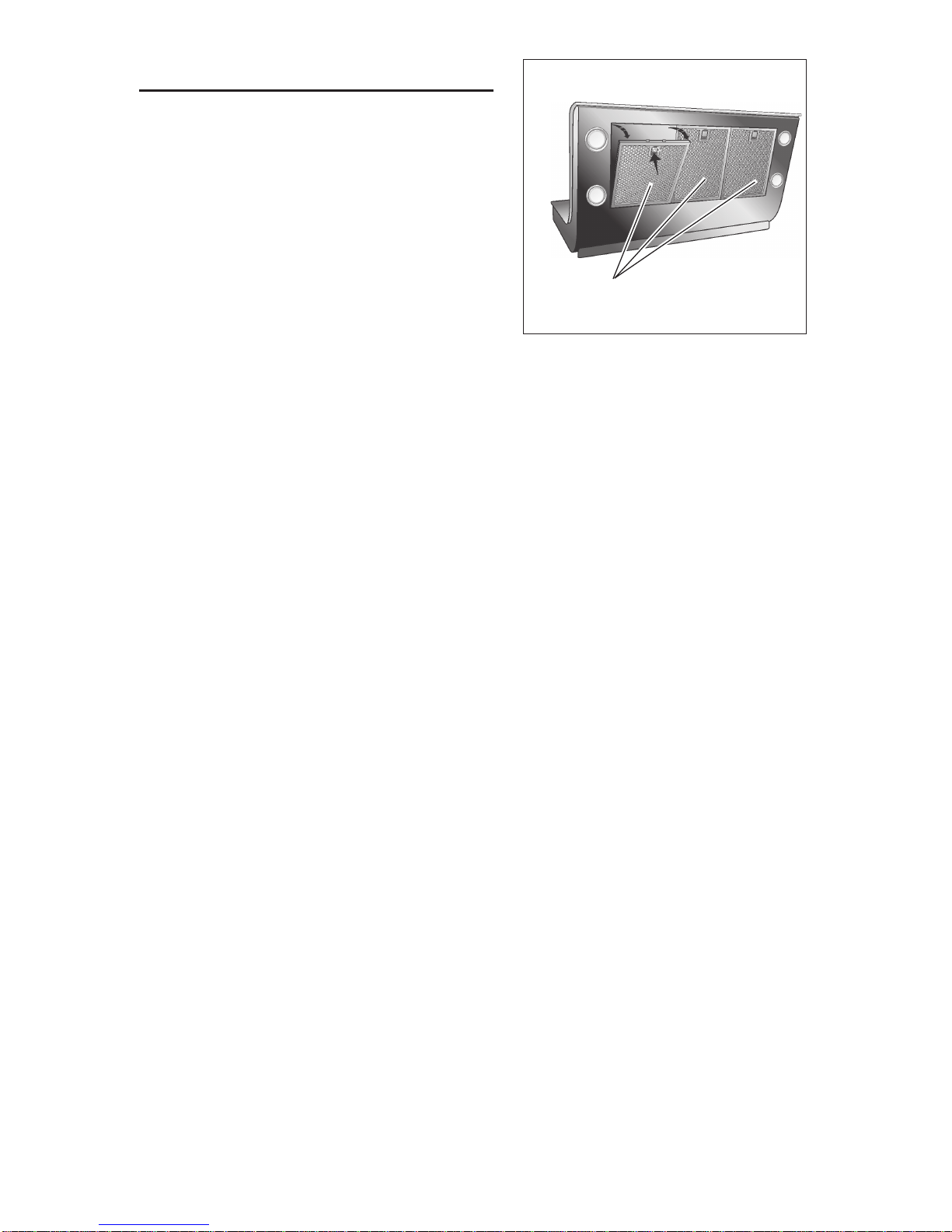
C. Cleanventilatingfansfrequently.Greaseshouldnot beallowedtoaccumulateon fanor
filter.
D. Use proper pan size. Always use cookware appropriate for the size of the surface
element.
WARNING
TOREDUCE THE RISKOF INJURYTO PERSONS INTHE EVENT OFA RANGETOP
FIRE,OBSERVETHEFOLLOWING:*
1. SMOTHERFLAMESwitha close-fittinglid,cookiesheet,ormetaltray, thenturnoff the
burner.BE CAREFULTOPREVENT BURNS.If theflamesdo notgo outimmediately,
EVACUATEANDCALLTHEFIREDEPARTMENT.
2. NEVERPICKUP AFLAMINGPAN -Youmaybeburned.
3. DONOTUSEWATER,includingwetdishclothsortowels-aviolentsteamexplosionwill
result.
4. Useanextinguisher ONLYif:
A. You know you have a Class ABC extinguisher, and you already know how to
operateit.
B. Thefire issmall andcontained intheareawhereit started.
C. Thefiredepartment isbeingcalled.
D. Youcan fightthe fire withyour backto an exit.
*Based on“Kitchen FireSafety Tips”publishedbyNFPA.
!
INTENDED FOR DOMESTIC COOKING ONLY
!

- 3 -
!
CAUTION
1. Toreduceriskoffireandtoproperlyexhaust air,besuretoductairoutside.Donotvent
exhaustairinto spaceswithin wallsorceilings orintoattics, crawlspaces, orgarages.
2. Takecarewhen usingcleaning agentsor detergents.
3. Avoidusingfood productsthatproduceflamesunder theRange Hood.
4. Forgeneralventilating useonly. Donot useto exhausthazardousor explosivemate-
rialsand vapors.
5. Toavoidmotorbearing damageand noisyand/orunbalanced impellers,keepdrywall
spray,construction dust, etc.off power unit.
6. Yourhoodmotorhas athermaloverload whichwillautomatically shutoffthe motorifit
becomesoverheated.Themotor willrestartwhenit coolsdown.Ifthe motorcontinues
toshut off andrestart, have thehood serviced.
7. Forbestcaptureof cookingimpurities,the bottomofthehoodshouldbea minimumof
23-3/8"and amaximum of30" abovethe cookingsurface.
8. Threeinstallersare recommendedbecause ofthe largesize andweightofthishood.
9. This product isequipped with athermostat which maystart blower automatically.To
reduce the risk of injury and to prevent power from being switched on accidentally,
switchpower off atservice panel andlock or tagservice panel.
10. Usewithapproved cord-connectionkit only.
11. Pleasereadspecification labelonproduct forfurtherinformation andrequirements.
12. To reduce the risk of fire and electric shock, install this range hood only with Best by
BroanExteriorblowermodelsEB6,EB9,EB12,orEB15, orBestbyBroanIn-LineBlower
modelsILB3,ILB6,ILB9, orILB11.OtherBlowers cannotbesubstituted(Blowers sold
separately).

- 4 -
MAINTENANCE
Proper maintenance of the Range Hood will
assure proper performance of the unit.
Grease Filters
The grease filters must be cleaned
approximately once every 30 hours of
operation (when the icon D1 goes on).
Usea warmdetergentsolution. Greasefilters
is dishwasher safe.
Remove the filters: pull the handle outside
and unlock the filter.
HoodCleaning
Cleaning tips:
OWarm water with mild detergent is all that is usually needed.
OFollow all cleaning by rinsing with clear water. Wipe dry with a clean, soft cloth to
avoid water marks.
ODO NOT allow deposits to remain for long periods of time.
ODO NOT use ordinary steel wool or steel brushes.
ODO NOT allow salt solutions, disinfectants, bleaches, or cleaning compounds to
remain in contact for extended periods. Many of these compounds contain chemi-
cals which may be harmful. Rinse with water after exposure and wipe dry with a
clean cloth.
GREASEFILTERS

- 5 -
OPERATION
Controls
Pushbutton P1:LIGHTS.PushthebuttononcetoturnthelightsON-pushasecond
timetoturn the lights ON to a brighterlevel- push a third time to turnthelights OFF.
Push button P2: MOTOR: Switch on and off the motor. Switch on the motor to the
latest used speed and if pressed different times changes the speed in a cyclic way
(1,2,3,4,1,2…..) The speed set is visualized by the icon D5 and simultaneously the
icon D8 switches on ( the speed of the rotational movement is proportional to the
speed ). To the maximum speed the icon D8 switches off and the icon D3 switches
on.
Toswitchoffthemotor,pressthepushbuttonP2forabout 2seconds(thesetspeed
is memorized).
Push button P3: Switch on and off the functions D4(SENSOR) and/or D7 (Air
Refresh).
Push button P4: Reset grease filters and non-ducted recirculation filters.
Icon D1: GREASE FILTERS. It switches on when the grease filter must be cleaned
(after about 30 hours of working). One time the grease filters is cleaned, to make
the hours calculation start again, press the push button P4.
Icon D3 : MAXIMUM SPEED. Is activated only when the maximum speed is set.
Icon D4: SENSOR: To activate the sensor function, press the push button P3. To
disconnect the sensor, repeat the same operation. When the sensor activated, the
hood switches on automatically in the presence of any kinds of odours or vapours,
smokesorheat,causedbythecookingprocessandalsointhepresenceofpossible
and anomalous gas emissions in environment.
Icons D5 and D6: DISPLAY. Shows the set speed. Shows the sensor sensitivity.
Icon D7: AIR REFRESH: To start the function Air refresh, press the button P3 (the
icon goes on);
To disconnect the function Air refresh, repeat the same operation. The function Air
Refresh activates only if the motor is not working. Starting the function Air Refresh,
the hood recycles the air in the environment in perfect silence, starting every 50
minutes (for 10 minutes, at the first speed).
Icon D8 : ENGINE ON. The icon switches on when the engine is at the first, second
orthirdspeed.Tothefourthspeed,theiconswitchesoffandthe iconstartsworking
to the maximum speed (icon D3).
Icon D10: NON -DUCTED RECIRCULATION FILTERS (For the non-ducted
recirculation hood). It switches on when it is time to replace the non-ducted
recirculation filters (after about 120 working hours). One time the non-ducted
recirculation filters is replaced, to make the hours calculation start again press the
button P4.
Modification of sensor sensitivity:
Simultaneously press push button P3 and P4 (the sensor’s sensitivity index will
appear on the display D5); press the push button P3 to change the sensor’s
sensitivity (1 : minimum sensitivity / 9: maximum sensitivity). Press the push button
P4 to confirm (or is confirmed automatically after 5 seconds).

- 6 -
FUSE REPLACEMENT
IF LIGHTS FAIL TO OPERATE, DISCON-
NECT POWER AT THE SERVICE EN-
TRANCE. CHECK THE FUSE AND RE-
PLACE IF NECESSARY.
1. Remove the grease filters.
2. Unscrew the cap from the fuse holder
and remove the fuse.
3. Replace the fuse with the same size and
amperage (5 x 20mm, 4 amp, 125 volt).
!
CAUTION: Use a fuse greater than 4
amps may damage the transformer.
4. Reinstall the fuse holder cap.
5.Reconnectpowerattheserviceentrance.
FUSE
HALOGEN BULBS
This range hood requires four halogen bulbs
(Type T3, 12Volt, 20Watt Max, G-4 Base).
WARNING: Always switch off the elec-
trical supply before carrying out any op-
eration on the appliance.
To change bulbs:
1. Open the cover by prying from the proper
slots.
2. Removethebulbbypullingsideways.(DO
NOTROTATE).
!
CAUTION: Bulb may be hot.
3. Replace with Type T3, 12Volt, 20 Watt Max, G-4 Base halogen bulb. Do not touch
replacement bulb with bare hands!
!
CAUTION: Use of bulbs greater than 20 watts will cause the fuse to open.
HEAT SENTRY™
Your hood is equipped with a HEAT SENTRY™ thermostat. This thermostat is a
device that will turn on or speed up the blower if it senses excessive heat above
the cooking surface.
1) If blower is OFF - it turns blower ON to HIGH speed.
2) If blower is ON at a lower speed setting - it turns blower up to HIGH speed.
When the temperature level drops to normal, the blower will return to its original
setting.
WARNING
The HEAT SENTRY thermostat can start the blower even if the hood is turned
OFF. When this occurs, it is impossible to turn the blower OFF with its switch.
If you must stop the blower, do it from the main electrical panel.

- 7 -
PREPARE THE HOOD
Unpack hood and check contents.
You should receive:
1 - Hood
1 - Decorative Flue
1 - Parts Bag (B080810765) containing:
1 - Cover
4 - Mounting Screws (4.8 x 38mm Pan Head)
4 - Mounting Screws (3.9 x 6mm Flat Head)
2 - Brackets
1 - Parts Bag (B080810621) containing:
1 - Discharge Collar
4 - Mounting Screws (3.9 x 9.5mm Pan Head)
4 - Mounting Screws (3.9 x 9.5mm Pan Head - Black)
2 - Small Brackets
1 - Installation Instructions
1 - Warranty Card
COVER
4 MOUNTING SCREWS
(4.8 x 38mm Pan Head)
4 MOUNTING
SCREWS (3.9
x 6mm Flat
Head)
DISCHARGE
COLLAR
4 MOUNTING
SCREWS (3.9
x 9.5mm Pan
Head)
2 BRACKETS
DECORATIVE
FLUE
2 SMALL
BRACKETS
4 MOUNTING
SCREWS (3.9
x 9.5mm Pan
Head - Black)

- 8 -
23-3/8” TO 30” ABOVE
COOKING SURFACE
23-3/8” TO 30” ABOVE
COOKING SURFACE
EXTERIOR OR IN-LINE BLOWER SELECTION
CAUTION: Either an exterior blower or in-line blower may be used with this hood.
The WM24E hood must be installed with blower models EB6, EB9, EB12, EB15,
ILB3, ILB6, ILB9, or ILB11 only. Other Blowers cannot be substituted (Blowers sold
separately).
TheblowermustbeULlistedforCanadianandU.S.use,andevaluatedforusewith
solid state speed control, rated 120V, 60 Hz, 6.0 A max.
8” ROUND
DUCT
INSTALL THE DUCTWORK
NOTE: To reduce the risk of fire, use only
metal ductwork.
1. Choose the location where the Exterior
or In-Line Blower will be mounted. See
illustrations below for mounting location
suggestions and restrictions.
2. A straight, short duct run will allow the
hood to perform most efficiently.
3. Long duct runs, elbows and transitions
will reduce the performance of the hood.
Use as few of them as possible. Larger
ducting may be required for best
performance with long duct runs.
4. After the Exterior or In-Line Blower has
been installed, connect round metal
ductwork and work back towards the
hood location. Use duct tape to seal
joints between ductwork sections.
5. An8”roundto10” round transition(Model
414)is required.Forbestairperformance,
install the transition as close to the range
hood as possible.
OK
OK
SUGGESTED MOUNTING LOCATIONS
EXTERIOR BLOWER
CAUTION: MAY NOT FIT
UNDER EAVES OF SINGLE
STORY HOMES
HOOD
8-5/16”
DUCTWORK ON THE CEILING DUCTWORK ON THE WALL
HOOD
4-3/4”
10” ROUND
DUCT EXTERIOR
BLOWER
8” TO 10”
ROUND
TRANSITION
EXTERIOR
BLOWER
8” TO 10”
ROUND
TRANSITION
10”
ROUND
DUCT
8-1/8”
1-1/4”

- 9 -
IN-LINE BLOWER

- 10 -
WIRING
CAUTION: All electrical wiring should
be done by a qualified person (s) in
accordance with all applicable codes and
standards. This range hood must be
properly grounded. Turn off electrical
power at service entrance before wiring.
Donot turn poweron atservicepanel until
all wires have been connected.
Blower connection at hood:
1. Run conductors (2-wire plusground)from
theExteriororIn-LineBlowertothehood’s
wiring box marked “motor connection”.
See Fig. 1 if the ductwork is placed on the
ceiling;seeFig.2 iftheductworkisplaced
on the wall.
2. Remove the cover from the wiring box.
Fig. 1 or 2.
3. Secure the conduit to the wiring box
through a conduit connector. Fig.1 or 2
4. Make electrical connections at the hood.
Connectwhite-to-white,red-to-blackand
green-to-ground. Fig.1 or 2.
5. Replace the wiring box cover and screws.
Makesurewiresare not pinched between
the cover and box.
Exterior or In-line blower connection:
1.Make electrical connections at the
exteriororin-lineblower(seeinstructions
provided with the exterior or in-line
blower).
FIG. 1
FIG. 2
BLOWER CONNECTION AT
HOOD (DUCTWORK ON THE CEILING)
BOX MARKED
“MOTOR
CONNECTION”
CONNECT:
WHITE-TO-WHITE,
RED-TO-BLACK,
GREEN-TO-GROUND.
BLOWER CONNECTION AT
HOOD (DUCTWORK ON THE WALL)
Exterior or In-Line
blower
BOX MARKED
“MOTOR
CONNECTION”
CONNECT:
WHITE-TO-WHITE,
RED-TO-BLACK,
GREEN-TO-GROUND.
Exterior or In-
Line blower

- 11 -
FIG. 3
BOX
MARKED
“120 VAC
INPUT”
CONNECT:
WHITE-TO-WHITE,
BLACK-TO-BLACK,
GREEN-TO-GROUND.
120 Volt 60Hz
LINE-IN
POWER CONNECTION AT HOOD
Power connection at hood:
1. Run supply conductors to the hood wiring
box marked “120VAC input”. Fig. 3.
2. Remove the wiring box cover.
3. Secure the conduit to the wiring box
through a conduit connector. Fig. 3.
4. Make electrical connections at the hood.
Connect white-to-white, black-to-black
and green-to-ground. Fig. 3.
5. Replace the wiring box cover and
screws. Make sure wires are not pinched
between the cover and box.

- 12 -
PREPARE THE HOOD
Note: Carefully remove the plastic
protective film from all exterior surfaces
of the hood and decorative flue, prior to
finalinstallation.
1. To avoid demage while forwarding the
applicance has been locked by means of
four screws to a laminboard panel on the
bottom of the packing.
To separate the hood from the panel:
a. Disassemble the central block: rotate
the block outside softly (Fig. 4).
b. Remove the 4 screws (Fig. 5).
2. Fit the 2 brackets on the central block in
suchaway thatthe two slots are plugged.
Eachbracketmustbe fixed with (2) 3.9x6
mm mounting screws (Fig. 6).
3. Attach the discharge collar onto the hood
(Fig. 7); it must be attached by means of 4
mountingscrews(3,9x9,5mm PanHead).
4. Remove the tape located on the damper
(Fig. 7).
5. Attach an adequate length of 8” round
steel ducting to the range hood discharge
collar (Fig. 8).
Duct tape all joints to make them secure
and air tight.
6. Iftheductworkisplacedonthewall(and
not on the ceiling), read the following
instructions:
- disassemble the motor block (included
theplatewhere itisfixed)unscrewing the
4 screws (Fig. 9).
- rotate motor block in order to have the
duct connector toward the wall.
CENTRAL BLOCK
FIG. 4
FIG. 6
BRACKETS
MOUNTING SCREWS
(3.9x6mm)
FIG. 5
FIG. 7
DISCHARGE COLLAR
REMOVE THE TAPE

- 13 -
FIG. 9 FIG.10
8” DIAMETER
DUCT
DISCHARGE
COLLAR
FIG. 8
MOUNTING SCREWS
(3.9x9.5mm - Black)
- use the same screws to fix the motor
block in the new position (Fig. 10).
7. For 9’ or 10’ ceilings, mount the the (2)
small brackets of the decorative flue with
(2)mountingscrews(3.9x9.5mm-Black).
Fig.11.
SMALL
BRACKETS
FIG.11

- 14 -
INSTALL THE HOOD
Note: at least 3 people will be required to mount the hood.
1. Make on the wall 4 holes (D. 8mm), according to the measures indicated in the
Fig. 12.
2. Securethehoodwith(4)mountingscrews
(4.8x38mm).
3. Make the electrical connection (see
“Install Electrical”).
4. Reassemble the central block.
5. For9’or10’ceilings,mountthedecorative
flue. For 9’ ceilings, the decorative flue is
supplied. For 10’ ceilings, purchase a
decorative FLUE KIT from your dealer.
Secure the flue with (2) mounting screws
(3.9x9.5mm). Fig. 13.
FIG.13
DECORATIVE
FLUE
MOUNTING SCREWS
(3.9x9.5mm - Black)
FIG.12
7-7/8”
1-1/8”
13-15/16”
45” to
51-3/8”
above
cooktop
MOUNTING
SCREWS
(4.8x38mm)
45" = bottom of hood 23-5/8" above cooktop
51-3/8" = bottom of hood 30" above cooktop
8’ CEILING

- 15 -
WARRANTY
BROAN ONE YEAR LIMITED WARRANTY
Broanwarrants tothe originalconsumer purchaser of its productsthat suchproducts will be free fromdefects inmaterials
or workmanship for a period of one year from the date of original purchase. THERE ARE NO OTHER WARRANTIES,
EXPRESS OR IMPLIED, INCLUDING, BUT NOT LIMITED TO, IMPLIED WARRANTIES OR MERCHANT ABILITY OR
FITNESS FOR A PARTICULAR PURPOSE.
Duringthis one-yearperiod,Broan will,at its option,repair or replace,without charge,any product orpart which isfound to
bedefective undernormal use andservice.
THIS WARRANTY DOES NOT EXTEND TO FLUORESCENT LAMP STARTERS, TUBES, HALOGEN AND
INCANDESCENDTBULBS. This warranty doesnotcover (a) normalmaintenance and serviceor(b) any productsor parts
which have been subject to misuse, negligence, accident, improper maintenance or repair (other than by Broan), faulty
installationor installationcontrary to recommended installation instructions.
Theduration of anyimpliedwarranty is limitedtothe one-year periodasspecified fortheexpress warranty. Some statesdo
not allow limitation on how long an implied warranty lasts, so the above limitation may not apply to you.
BROAN’SOBLIGATIONTO REPAIR ORREPLACE,AT BROAN’S OPTION, SHALLBETHE PURCHASER’S SOLEAND
EXCLUSIVEREMEDY UNDER THISWARRANTY. BROANSHALL NOT BELIABLEFOR INCIDENTAL, CONSEQUEN-
TIAL OR SPECIAL DAMAGES ARISING OUT OF OR IN CONNECTION WITH PRODUCT USE OR PERFORMANCE.
Some states do not allow the exclusion or limitation of incidental or consequential damages, so the above limitation or
exclusionmay notapply to you.
Thiswarrantygivesyouspecific legal rights, andyoumayalsohaveother rights, which varyfromstatetostate. Thiswarranty
supersedes all prior warranties.
Toqualifyfor warranty service,youmust(a) notify Broanattheaddress stated belowortelephone:1-800-637-1453, (b) give
themodelnumberandpartidentificationand(c)describe thenatureofanydefectinthe productorpart. Atthetimeofrequesting
warrantyservice, youmust present evidenceof theoriginal purchase date.
BEST BY BROAN, P.O. Box 140 Hartford, Wisconsin 53027

- 16 -
LISEZ ET CONSERVEZ CES INSTRUCTIONS
AVERTISSEMENTS
POUR REDUIRE LES RISQUES D’INCENDIE, DE DECHARGES ELECTRIQUES OU
DE DOMMAGES AUX PERSONNES, OBSERVEZ LES INSTRUCTIONS SUIVANTES:
1. N’utilisezcetappareilquecommecelaestindiquéparleconstructeur.Sivousavezdes
problèmes,contactezlefabriquantàl’adresseouaunumérodetéléphoneindiquésdans
lagarantie.
2. Avantdepourvoiràl’entretienouaunettoyagedevotreappareil,éteignez-leautableau
descommandesoubloquezletableaudescommandesafind’éviterdelemettreenmarche
accidentellement.Sivousnepouvezpasbloquerlesystèmepermettantd’éteindrevotre
appareil,appliquezunavertissementextérieurd’unefaçonsure,commeparexempleun
panneau,surletableaudescommandes.
3. L’assemblageetlaconnexionélectriquedoiventêtrefaitspardespersonnesqualifiées
enrespectantlesnormesetrèglementsenvigueur,ycomprislesnormesetrèglements
concernantlespossibilitésd’incendie.
4. Ilestindispensablequ’ilyaitsuffisammentd’airpourquelacombustionetl’évacuationdes
gazàtraversletuyaudubrûleurducombustibleaitlieusansretourdeflamme.Suivez
lesindicationsdonnéesparlefabricantdubrûleurainsiquelesnormesdesécuritécomme
cellesquisontpubliéesparl’AssociationNationalepourlaProtectioncontrelesIncendies
NationalFireProtectionAssociation(NFPA)etlaAmericanSocietyforHeating,Refrigeration
andAirConditioningEngineers(ASHRAE),etlesautoritéslocalesenmatièredenormes.
5. Quandvouscoupezoupercezdestrousdanslemurouleplafond,n’abîmezpaslesfils
électriquesouautres.
6. Leventilateurcanalisédoittoujoursévacuerl’airversl’extérieur.
7. N’utilisezpascetappareilavecunappareilcontrôlantlavitesseàétatsolide.
8. Afindediminuertoutrisqued’incendien’utilisezquedesconduitsenmétal.
9. Votreappareildoitêtrereliéàlaterre.
ATTENTION-POURREDUIRELESRISQUESD’INCENDIEDESMATIERESGRASSES
QUISONT ENTRAIN DECUIRE:
A. Ne laissez jamais ni vos éléments chauffants, ni vos casseroles ou poêles sur le feu
sans les contrôler si vous réglez l’apport de chaleur sur une position élevée. Si vos
casserolesou poêles débordentcela provoque dela vapeuret des éclaboussuresde
graissequi peuventprendre feu.Chauffezles huileslentement àfeu basou moyen.
B. Faitestoujours fonctionnervotre hottequand vouscuisez àdes températuresélevées
ou quand vous cuisinez des plats flambés. (par ex. crêpes Suzette, Cerises “Jubilé”,
Steackau poivreflambé).
C. Nettoyezrégulièrement lesailes devos ventilateurs.Nepermettez pasque lagraisse
s’accumulesur leventilateur ousur lefiltre.
D. Utilisezdescasseroles detaille appropriée.Utiliseztoujours desustensilesde cuisson
dontla tailleest appropriéeà lasurface devotre élémentde cuisson.
AVERTISSEMENTS
POURREDUIRELESRISQUESDEDOMMAGESAUXPERSONNESAUCASOÙVOTRE
CUISINIEREPRENDRAITFEU,OBSERVEZLESINSTRUCTIONSSUIVANTES:*
1. ETEINDRE LES FLAMMES à l’aide d’un couvercle le plus hermétique possible, une
plaqueà gâteaux, ouun plateauen métal, puiséteindre lebrûleur. ATTENTION àNE
PASVOUSBRÛLER. Silesflammes nes’éteignentpas immédiatement,SORTEZET
APPELEZLESPOMPIERS.
2. NEPRENEZJAMAISENMAINUNE POÊLEOUUNECASSEROLEQUI APRISFEU
-Vous pourriez vousbrûler.
3. N’UTILISEZPAS D’EAU, ni torchons ouserviettes mouillés -vous provoqueriez une
violenteexplosionde vapeur.
SEULEMENT POUR UTILISATION DOMESTIQUE
!!

- 17 -
4. UtilisezunextincteurSEULEMENT si:
A. Voussavez quevousavez unextincteurClasseABC,etvousen connaissezdéjàle
moded’emploi.
B. Cen’est pasun trèsgros incendieet qu’ilse limiteà l’endroioù ila explosé.
C. Vousêtes entrain d’avertirles pompiers.
D. Vousavez lapossibilité d’essayerd’éteindre l’incendie enayant ledos tourné vers
uneissue.
* D’après les “Suggestions concernant la Sécurité contre les incendies des cuisines”
publiéesparNFPA.
ATTENTION
1. Pourréduiretoutrisqued’incendie etpourévacuercorrectementl’air, assurez-vousde
prévoirun conduitde ventilationextérieur. Ne videzpas l’airdans lesespaces limités
pardes murs oudes plafonds,les combles, lespassages étroits oules garages.
2. Faitestrèsattentionquand vousutilisez desproduitsde nettoyageou desdétergents.
3. Évitezd’utiliserdesaliments pouvants’enflammersous laRangeHood.
4. N’utilisezcetappareilque pouruneventilationgénérale. Nel’utilisezpas pourévacuer
desmatières oudes vapeursdangereuses ou quipeuvent exploser.
5. Pouréviterdecauser desdommages aumoteuret derendreles rotorsbruyants et/ou
non équilibrés, évitez que les sprays pour murs secs, la poussière de construction
entrenten contactavec lapartie électrique.
6. Lemoteurdevotrehotteaunthermostatquiéteindraautomatiquementlemoteurs’ilest
surchauffé. Le moteur se remettra en marche lorsqu’il se sera refroidi. Si le moteur
continueà s’éteindreet àse remettreen marche,faitesvérifier votrehotte.
7. Pourmieuxcapturer lesimpuretés de cuisine,le basde votrehotte devrait êtreà une
distanceminimumde23-3/8”(59.4cm)etàunedistancemaximumde30” (76.2cm)au-
dessusdu plan decuisson.
8. Vuquecette hotte estgrande etlourde, il estrecommandé deconfier l’installation de
cettehotte à3 personnes.
9. Ce produit est doté d’un thermostat qui active automatiquement le moteur. Pour
réduirelerisquededommagesetéviterl’activationaccidentelle,positionnerl’interrupteur
dupanneaude servicesur lapositionOFF etbloquerle panneaude serviceoumettre
unavertissement externe, parexemple une plaquette.
10. Utiliseruniquementavec unkit deconnexion pour alimentationhomologué.
11. Nous vous recommandons de lire l’étiquette indiquant les caractéristiques de votre
hottepour deplusamplesinformations etexigences.
12. Pour diminuer les dangers d’incendie ou de choc électrique, installer cette hotte de
cuisineuniquementparmilesmodèlesdeventilateursexterne“BestdeBroan”modèles
EB6, EB9, EB12, ou EB15, ou ventilateurs “In-Line, Best de Broan” Modèles ILB3,
ILB6,ILB9, ou ILB11. Onne peut pas utiliserd’autres ventilateurs (Les ventilateurs
sont vendus séparément).
!

- 18 -
ENTRETIEN
Un bon entretien de votre hotte garantira
une excellente performance.
Filtres anti-graisse :
Les filtres anti-graisse doivent être
nettoyés environ toutes les 30 heures de
fonctionnement (lorsque l’icône D1
s’allume). Utilisez une solution contenant
un détergent tiède. Les filtres anti-graisse
peuvent être lavés au lave-vaisselle.
Enlevez les filtres: tirer la poignée vers
l’externe et décrocher le filtre.
Nettoyage de votre hotte
Conseils pour le nettoyage:
OEau tiède additionnée d’un détergent doux est tout ce qui est normalement
nécessaire.
OAprès chaque nettoyage, rincez bien à l’eau claire. Essuyez avec un chiffon
propre et doux afin d’éviter les taches d’eau.
ONE LAISSEZ PAS les taches trop longtemps.
ON’UTILISEZ PAS de laines d’acier ordinaires ou des brosses en acier.
ONE PERMETTEZ PAS que des solutions salées, des désinfectants, des
blanchissants ou des produits nettoyants restent en contact pendant longtemps.
Beaucoup de ces produits contiennent des produits chimiques qui pourraient
causer des dommages. Rincez à l’eau immédiatement s’ils entrent en contact et
essuyez avec un chiffon humide.
FILTRESANTI-GRAISSE

- 19 -
FONCTIONNEMENT
Commandes
Touche P1: ECLAIRAGE. En pressant 1 fois la touche, la lumière s’allume au 1er
niveau; en pressant 2 fois la touche, la lumière du 2ème niveau s’allume (éclairage
plus intense); en pressant encore une fois la touche, la lumière s’éteint.
Touche P2: MOTEUR. Active/Désactive le moteur. Active le moteur à la dernière
vitesseutilisée,etsionlapresseàplusieursreprisesellechangelavitessedefaçon
cyclique (1, 2, 3, 4, 1, 2....). La vitesse établie est visualisée par l’icône D5 et, en
mêmetemps,l’icôneD8s’active(lavitessedumouvementrotatifestproportionnelle
à la vitesse ). L’icône D8 se désactive et l’icône D3 s’active à la vitesse maximum.
Pour arrêter le moteur presser la touche P2 pendant 2 secondes environ (on met
en mémoire la vitesse établie).
Touche P3: Sélectionne/Déselectionne les fonctions D4 (CAPTEUR) et/ou D7 (Air
Refresh).
Touche P4: Reset filtres à graisse et filtres à charbon.
Icône D1: FILTRES À GRAISSE. Elle s’allume quand il est temps de nettoyer le/
s filtre/s à graisse (après environ 30 heures de fonctionnement de la hotte). Une
fois nettoyes les filtres à graisse, presser la touche P4 pour faire repartir le
comptage.
IcôneD3: VITESSEMAXIMUM.Elles’activeseulementquandlavitesse maximum
est établie.
Icône D4: CAPTEUR. Pour activer la fonction capteur, presser la touche P3. Pour
désactiver le capteur, répéter la même opération. Avec le capteur activé, la hotte
s’actionne automatiquement en présence de n’importe quel type d’odeur, vapeur,
fumée ou chaleur provoquée par le processus de cuisson et même en présence
d’éventuelles fuites de GAZ dans l’environnement.
Icônes D5 et D6: DISPLAY. Il visualise la vitesse établie. Il visualise la sensibilité
du capteur.
IcôneD7:AIRREFRESH.Pouractiver lafonctionAirRefresh,presserlatoucheP3
jusqu’à ce que l’icône s’allume. Pour désactiver la fonction Air Refresh répéter la
même opération.
La fonction Air Refresh s’active seulement si le moteur n’est pas en marche. En
activant la fonction Air Refresh, la hotte change l’air dans le local dans un silence
absolu, en s’actionnant toutes les 50 minutes (pour une durée de 10 minutes, à la
première vitesse).
Icône D8: MOTEUR ON. L’icône s’allume quand le moteur est à la première,
seconde ou troisième vitesse. A la quatrième vitesse, l’icône s’éteint et l’icône
relative à la vitesse maximum s’active (icône D3).
IcôneD10:FILTRESÀCHARBON(pourlahotterecyclantl’air).Elles’allumequand
il est temps de remplacer les filtres à charbon (après environ 120 heures de
fonctionnement de la hotte). Une fois les filtres à charbon remplacés, pour faire
repartir le comptage des heures presser la touche P4.
Modification de la sensibilité du capteur:
appuyer en même temps sur les touches P3 et P4 (l’afficheur D5 visualise
l’indice de sensibilité du capteur); appuyer sur la touche P3 pour changé la
sensibilité du capteur (1 : sensibilité minimum / 9: sensibilité maximum).

- 20 -
FUSIBLE
REMPLACEMENT FUSIBLE
SI LES AMPOULES NE FONCTIONNENT
PAS, DÉBRANCHEZ L’ALIMENTATION À
L’ENTRÉEDE SERVICE. CONTRÔLEZ LE
FUSIBLE ET REMPLACEZ-LE SI
NÉCESSAIRE.
1. Retirez les filtres de graisse.
2. Dévissez la protection du support de
fusible et retirez le fusible.
3. Remplacez le fusible par un autre de
même taille et de même intensité (5 x
20 mm, 4 amp, 125 volts).
!
ATTENTION : L’utilisationd’un fusiblede plus de4 amps peut endommager
le transformateur.
4. Replacez la protection du support de fusible.
5. Rebranchez l’alimentation à l’entrée de service.
AMPOULES HALOGENES
Cemodèledehotteveutquatre(4)ampoules
halogènes(TypeT3,12Volt,20WattMax,G-
4 Base).
ATTENTION: avant de procéder à
quelconque opération, débranchez
l’appareil.
Pour changer les ampoules:
1. Ouvrezlecouvercleenfaisantleviergrâce
aux fissures prévues à cet effet.
2. Retirez l’ampoule en tirant latéralement.
(NE LA FAITES PAS TOURNER).
ATTENTION: l’ampoule peut être chaude!
3. Remplacer par une ampoule ayant les mêmes caractéristiques (T3, 12Volt, 20
Watt Max, G-4 Base). Ne touchez pas l’ampoule neuve de vos mains nues.
ATTENTION: L’utilisation d’ampoules de plus de 20 watts provoquera
l’ouverture du fusible.
Appuyer la touche P4 pour confermer (ou est confermé automatiquement
depuis 5”).
HEAT SENTRYMC
Votrehotteestmunied’unthermostatHEATSENTRYMC.Cethermostatestundispositif
qui actionnera ou augmentera la vitesse du ventilateur s’il détecte une chaleur
excessive au-dessus de la surface de cuisson.
1) Si le ventilateur n’est pas en marche - il actionnera le ventilateur en haute vitesse.
2) Si le ventilateur fonctionne en basse vitesse - le ventilateur tournera en haute
vitesse.
Lorsque la température revient à la normale, le ventilateur retourne à sa vitesse
d’origine.
AVERTISSEMENT
Le thermostat HEAT SENTRYMC peu actionner la hotte même si la hotte est
arrêtée. Si tel est le cas, il est impossible de l’arrêter avec l’interrupteur. Si vous
devez arrêter le ventilateur, faites-le à partir du panneau électrique principal.
Table of contents
Languages:
Other Best Ventilation Hood manuals

Best
Best P195P1M52 User manual

Best
Best P195ES70SB User manual

Best
Best K260A series User manual

Best
Best CP34 Series User manual

Best
Best UCB3I30SBW User manual

Best
Best PK22 User manual

Best
Best CP45I series User manual

Best
Best KEX273 User manual

Best
Best CP35 Series User manual

Best
Best WT32I SERIES User manual
Popular Ventilation Hood manuals by other brands

Omega
Omega ORU52GLED instruction manual

Kuppersberg
Kuppersberg IBOX 60 Technical Passport

Whirlpool
Whirlpool Amana UXW7324BSS Installation Instructions and Use & Care Guide

Whirlpool
Whirlpool GZ5730XRB1 Installation Instructions and Use & Care Guide

Windster
Windster RA=33 Series Operation manual

ROBLIN
ROBLIN PILOT MASTER PRO SM Dimensions