Best WM45I User manual

Model WM45I
ENGLISH.................................... 2
FRANÇAIS.................................17
ESPAÑOL.................................. 33
In USA - BEST Hartford, Wisconsin
In CANADA - BEST Drummondville, QC, Canada
REGISTER YOUR PRODUCT ONLINE AT : www.BestRangeHoods.com/register
For additional Information visit www.BestRangeHoods.com

- 2 -
READ AND SAVE THESE INSTRUCTIONS
WARNING
TO REDUCE THE RISK OF FIRE, ELECTRIC SHOCK, OR INJURY TO PERSONS, OBSERVE
THE FOLLOWING:
1. Use this unit only in the manner intended by the manufacturer. If you have questions, contact
the manufacturer at the address or telephone number listed in the warranty.
2. Before servicing or cleaning unit, switch power off at service panel and lock service panel to
prevent power from being switched on accidentally. When the service disconnecting means cannot
be locked, securely fasten a prominent warning device, such as a tag, to the service panel.
3. Installation work and electrical wiring must be done by a qualified person(s) in accordance with
all applicable codes and standards, including fire-rated construction codes and standards.
4. Sufficient air is needed for proper combustion and exhausting of gases through the flue (chimney)
of fuel burning equipment to prevent backdrafting. Follow the heating equipment manufacturer’s
guidelines and safety standards such as those published by the National Fire Protection
Association (NFPA), and the American Society for Heating, Refrigeration and Air Conditioning
Engineers (ASHRAE), and the local code authorities.
5. When cutting or drilling into wall or ceiling, do not damage electrical wiring and other hidden
utilities.
6. Ducted fans must always be vented to the outdoors.
7. Do not use this unit with any separate solid-state speed control device.
8. To reduce the risk of fire, use only metal ductwork.
GROUNDING INSTRUCTIONS
This appliance must be grounded. In the event of an electrical short circuit, grounding reduces the
risk of electrical shock by providing an escape wire for the electric current. This appliance is equipped
with a cord having a grounding wire with a grounding plug. The plug must be plugged into an outlet
that is properly installed and grounded.
WARNING - Improper grounding can result in a risk of electric shock.
Consult a qualified electrician if the grounding instructions are not completely understood, or if doubt
exists as to whether the appliance is properly grounded.
Do not use an extension cord. If the power supply cord is too short, have a qualified electrician install
an outlet near the appliance.
!
INTENDED FOR DOMESTIC COOKING ONLY
!

- 3 -
!
CAUTION
1. For indoor use only.
2. To reduce risk of fire and to properly exhaust air, be sure to duct air outside. Do not vent exhaust
air into spaces within walls or ceilings or into attics, crawl spaces, or garages.
3. Take care when using cleaning agents or detergents.
4. Avoid using food products that produce flames under the Range Hood.
5. For general ventilating use only. Do not use to exhaust hazardous or explosive materials and
vapors.
6. To avoid motor bearing damage and noisy and/or unbalanced impellers, keep drywall spray,
construction dust, etc. off power unit.
7. Your hood motor has a thermal overload which will automatically shut off the motor if it becomes
overheated. The motor will restart when it cools down. If the motor continues to shut off and
restart, have the hood serviced.
8. For best capture of cooking impurities, the bottom of the hood should be a minimum of 22”
and a maximum of 30” above the cooking surface. See “Install Mounting Bracket” section for
mounting restrictions.
9. Two installers are recommended because of the large size and weight of this hood.
10. This product is equipped with a thermostat which may start blower automatically. To reduce
the risk of injury and to prevent power from being switched on accidentally, switch power off at
service panel and lock or tag service panel.
11. Please read specification label on product for further information and requirements.
WARNING
TO REDUCE THE RISK OF A RANGE TOP GREASE FIRE:
A. Never leave surface units unattended at high settings. Boilovers cause smoking and greasy
spillovers that may ignite. Heat oils slowly on low or medium settings.
B. Always turn hood ON when cooking at high heat or when flambeing food (i.e. Crepes Suzette,
Cherries Jubilee, Peppercorn Beef Flambe’).
C. Clean ventilating fans frequently. Grease should not be allowed to accumulate on fan or filter.
D. Use proper pan size. Always use cookware appropriate for the size of the surface element.
TO REDUCE THE RISK OF INJURY TO PERSONS IN THE EVENT OF A RANGE TOP GREASE
FIRE, OBSERVE THE FOLLOWING:*
1. SMOTHER FLAMES with a close-fitting lid, cookie sheet, or metal tray, then turn off the burner.
BE CAREFUL TO PREVENT BURNS. If the flames do not go out immediately, EVACUATE AND
CALL THE FIRE DEPARTMENT.
2. NEVER PICK UP A FLAMING PAN - You may be burned.
3. DO NOT USE WATER, including wet dishcloths or towels - violent steam explosion will result.
4. Use an extinguisher ONLY if:
A. You know you have a Class ABC extinguisher and you already know how to operate it.
B. The fire is small and contained in the area where it started.
C. The fire department is being called.
D. You can fight the fire with your back to an exit.
* Based on “Kitchen Fire Safety Tips” published by NFPA.

- 4 -
OPERATION
Controls
The hood is operated using the (5) push buttons located on the front edge of the hood. Fig. 1.
The Light On/Off switch turns the lights on to high intensity and turns them off.
The Light Dimmer switch alternates light intensity from low to high.
The Blower Off/Speed switch turns the blower off and changes blower speed to four different
speed settings: high, medium-high, medium-low and low speed. Depress and hold the button
for 2 seconds to turn the blower off.
The Blower On/Speed switch turns the blower on to four different speed settings: Low,
medium-low, medium-high and high speed.
The Blower LED Indicators illuminate for each selected speed.
The Time Delay switch activates a delay off feature. When pushed, the blower will continue
to operate at the current speed setting for 10-minutes before automatically turning itself off.
The LED (on the right) flashes during operation.
The LED (on the right) is also used as a filter clean reminder. It will flash after 30 hours of
operation - indicating the need to clean the filters.
The Filter Alarm Reset switch is used to reset the 30-hour filter timer. After filters are cleaned
or replaced, press this switch once to reset the filter clean alarm.
HEAT SENTRY™
Your hood is equipped with a HEAT SENTRY™ thermostat. This thermostat is a
device that will turn on or speed up the blower if it senses excessive heat above
the cooking surface.
1) If blower is OFF - it turns blower ON to HIGH speed.
2) If blower is ON at a lower speed setting - it turns blower up to HIGH speed.
When the temperature level drops to normal, the blower will return to its original setting.
WARNING
The HEAT SENTRY thermostat can start the blower even if the hood is turned OFF. When
this occurs, it is impossible to turn the blower OFF with its switch. If you must stop the
blower, do it from the main electrical panel.
Light
On / Off
FIG. 1
Light
Dimmer Blower
Off / Speed Blower
On / Speed
Blower LED
Indicators Time Delay /
Filter Alarm
Reset
LED

- 5 -
HALOGEN BULBS
This range hood requires two halogen bulbs
(Type T4, 120Volt, 25Watt Max, G9 Base).
WARNING: Always switch off the
electrical supply before carrying out any
operation on the appliance.
To change bulbs:
1. Open the cover by prying from the proper
slots. Fig. 2.
2. Remove the bulbs by pulling sideways.
(DO NOT ROTATE).
!
CAUTION: Bulbs may be hot.
3. Replace with Type T4, 120Volt, 25Watt Max, G9 Base halogen bulbs. Do not touch replace-
ment bulbs with bare hands!
FIG. 2
CLEANING AND MAINTENANCE
Proper maintenance of the Range Hood will assure proper performance of the unit.
Motor
The motor is permanently lubricated and never needs oiling. If the motor bearings make excessive or
unusual noise, replace the motor with the exact service motor. The impeller should also be replaced.
Grease Filter
The grease filter should be cleaned frequently. Use a warm detergent solution. Grease filter is dishwasher
safe.
Clean all-metal filters in the dishwasher using a non-phosphate detergent. Discoloration of the filter may
occur if using phosphate detergents, or as a result of local water conditions - but this will not affect filter
performance. This discoloration is not covered by the warranty.
See “INSTALL FILTERS” section for removal and installation instructions.
Non-ducted Recirculation Filter
The non-ducted recirculation filter should be changed every 6 months. Replace more often if your
cooking style generates extra grease, such as frying and wok cooking. See “INSTALL FILTERS” section
for removal and installation instructions.
Stainless Steel Cleaning
DO:
• Regularly wash with clean cloth or rag soaked
with warm water and mild soap or liquid dish
detergent.
• Always clean in the direction of original polish
lines.
• Always rinse well with clear water (2 or 3 times)
after cleaning. Wipe dry completely.
• You may also use a specialized household
stainless steel cleaner.
DON’T:
•
Use any steel or stainless steel wool or any
other scrapers to remove stubborn dirt.
• Use any harsh or abrasive cleansers.
• Allow dirt to accumulate.
• Let plaster dust or any other construction
residues reach the hood. During construction/
renovation, cover the range hood to make sure
no dust sticks to the stainless steel surface.
Avoid: When choosing a detergent
• Any cleaners that contain bleach will attack stainless steel
• Any products containing: chloride, fluoride, iodide, bromide will deteriorate surfaces rapidly.
• Any combustible products used for cleaning such as acetone, alcohol, ether, benzol, etc., are highly
explosive and should never be used close to a range.

- 6 -
PREPARE THE HOOD
Unpack hood and check contents.
You should receive:
1 - Hood
1 - Decorative Flue Assembly
1 - Parts Bag containing:
1 - Mounting Bracket
1 - Flue Mounting Bracket
8 - Mounting Screws (4.8 x 38mm Pan Head)
4 - Mounting Screws (3.9 x 9.5mm Pan Head)
2 - Mounting Screws (3.9 x 6mm Flat Head)
8 - Drywall Anchors
1 - Installation Instructions
1 - Mounting Template - Hood
1 - Mounting Template - Flue
1 - Discharge Collar
MOUNTING
BRACKET
DISCHARGE
COLLAR
FLUE MOUNTING BRACKET 8 MOUNTING SCREWS
(4.8 x 38mm Pan Head)
8 DRYWALL
ANCHORS
4 MOUNTING
SCREWS (3.9 x
9.5mm Pan Head)
DECORATIVE
FLUE
2 MOUNTING
SCREWS (3.9 x 6mm
Flat Head)
FIG. 3

- 7 -
6" ROUND
DUCT
ROOF CAP
6" ROUND
ELBOW
22" TO 30" ABOVE
COOKING SURFACE
(see “INSTALL
MOUNTING BRACKETS”
section for mounting
restrictions)
WALL CAP
HOOD
DECORATIVE
FLUE
INSTALL THE DUCTWORK
DUCTED HOODS ONLY
CAUTION: To reduce the risk of fire, use
only metal ductwork.
1. Decide where the ductwork will run be-
tween the hood and the outside. Fig. 4.
2. A straight, short duct run will allow the
hood to perform most efficiently.
3. Long duct runs, elbows, and transitions
will reduce the performance of the hood.
Use as few of them as possible. Larger
ducting may be required for best perfor-
mance with longer duct runs.
4. Install a roof or wall cap. Connect round
metal ductwork to cap and work back
towards hood location. Use duct tape to
seal the joints between ductwork sections.
INSTALL ELECTRICAL
DUCTED and NON-DUCTED HOODS
WARNING : Electrical wiring must
be done by a qualified person(s) in ac-
cordance with all applicable codes and
standards. This range hood must be prop-
erly grounded. Turn off electrical power at
service entrance before wiring.
1. Plan where the hood will be located above
the cook top. Refer to the “PREPARE
WALL FOR HOOD MOUNTING” section
for hood mounting height options.
2. Install a standard 2” x 4” wall outlet box
and 3-blade 125 volt, 15 Amp grounded
receptacle. Fig. 5.
3. Mount the center of the wall outlet 32”
above the bottom of the hood.
4. Locate the box and the receptacle within
boundary shown and off center of the
ductwork (to allow for power cord plug
and flue clearance).
FIG. 4
FIG. 5
32”
4”
8”
CENTERLINE
OF HOOD

- 8 -
PREPARE WALL FOR
HOOD MOUNTING
DUCTED and NON-DUCTED HOODS
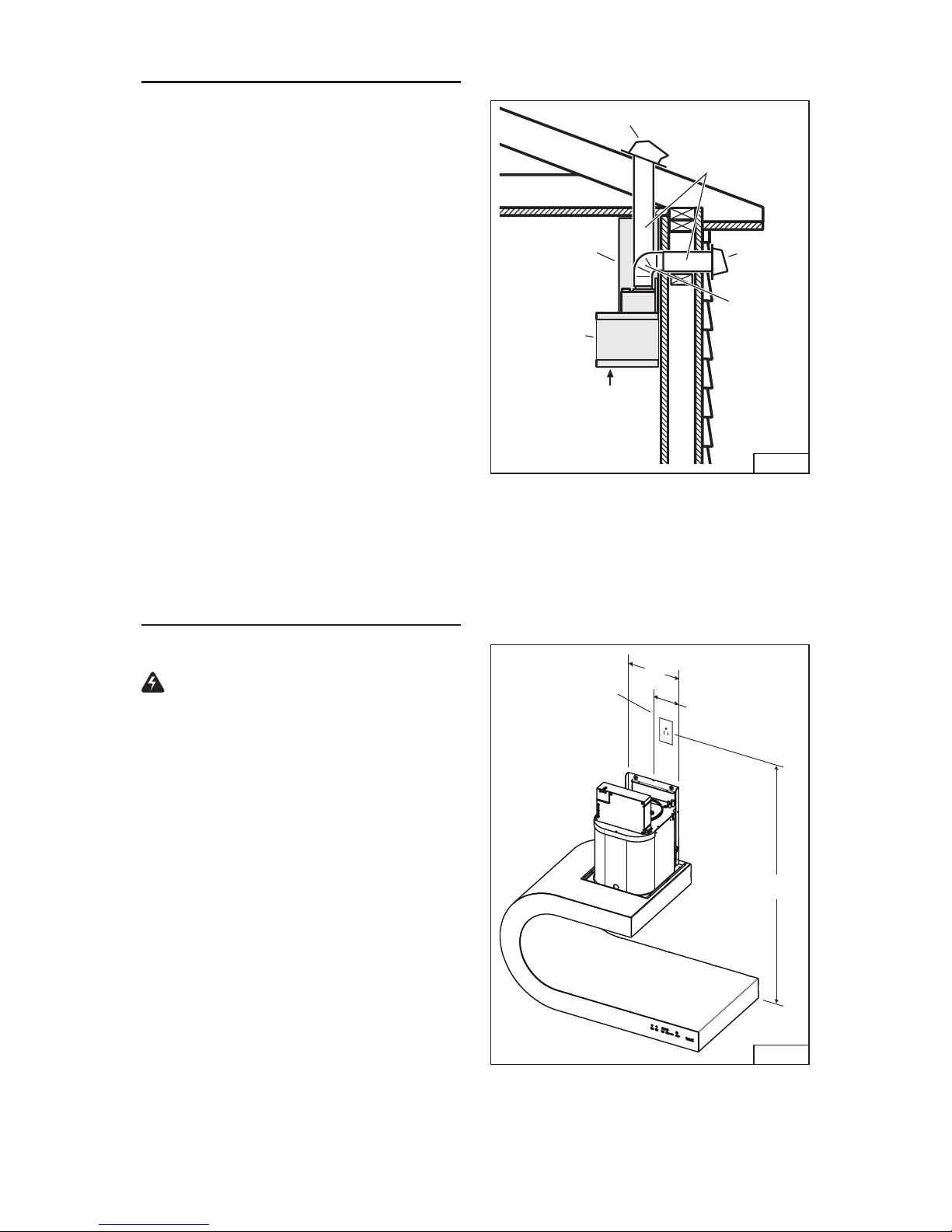
1. Decide what distance the hood will be
mounted above the cooktop. Refer to chart
below for mounting restrictions.
Note : Minimum hood distance above cook
top must not be less than 22”.
A maximum of 30” above cook top is highly
recommended for best capture of cooking
impurities.
Distances over 30” are at the installer and
user’s discretion; and if ceiling height and
flue length permit.
* Non-ducted installations require purchase
of non-duct kit Model ANKWM45.
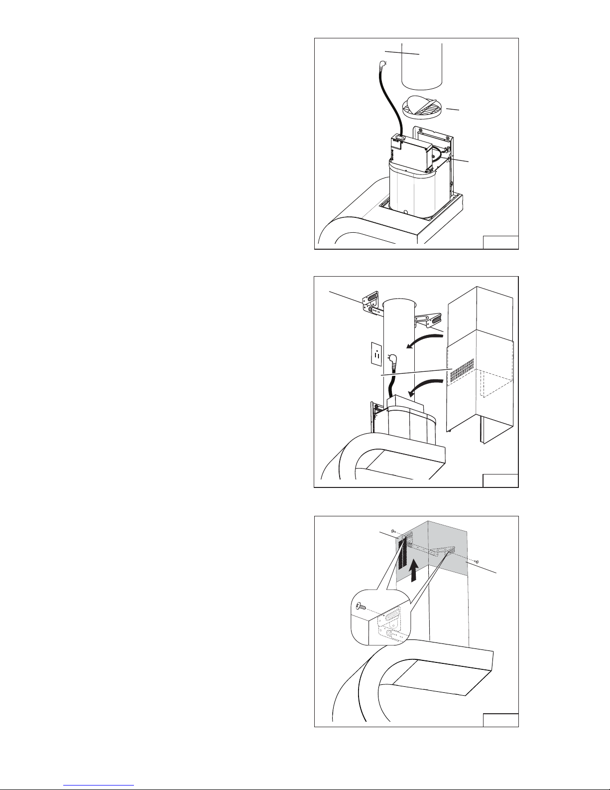
2. Construct wood wall framing that is flush
with interior surface of wall studs. Fig. 6.
Make sure:
a) to use the enclosed installation tem-
plate to size and position the wooden
frame.
b) the framing is correctly positioned
behind the mounting bracket location.
c) the frame is securely attached to at
least two (2) wall studs.
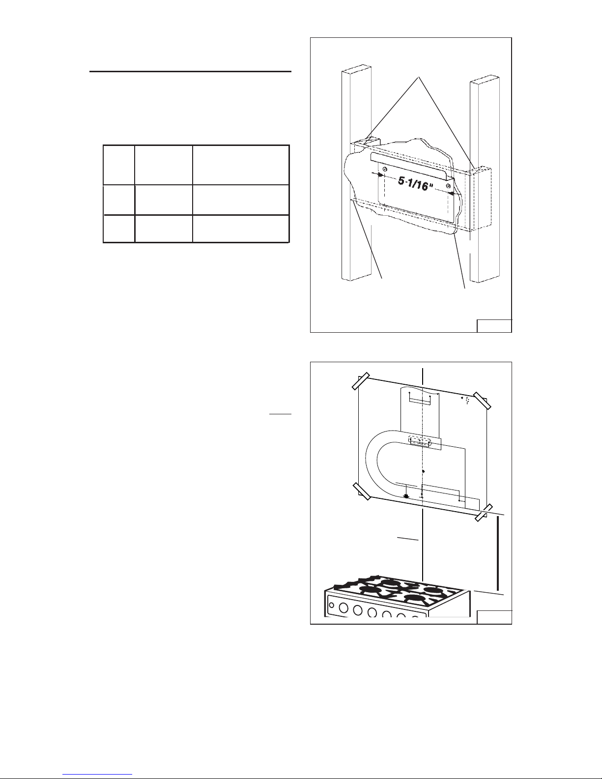
3. After wall surface is finished, attach
the enclosed installation template to wall.
Center it over cooktop and level with floor.
4. Mark center line of hood from template up
to where wall meets ceiling.
5. Drill (2) 1/8” diameter holes for the mount-
ing bracket.
6. Drill (4) 5/16” diameter holes for range
hood mounting. Remove template from
wall and install (4) drywall anchors into
these holes.
7. Fasten mounting bracket to wall with (2)
4.8 x 38 mm mounting screws.
FRAMING BEHIND
WOOD CROSS
SUPPORT
WOOD CROSS
SUPPORT BEHIND
DRYWALL
DRYWALL
FIG. 7
47
263
6
129
84.5 44.5
371
144
52
92
- Central axis
- Mittelinie
- Axe central
- Asse centrale
- Eje central
- Middellijn
- Eixo central
COD.04302150
HP
- Furos 8 para xação à parede utilizando os
- Perçages 8 pour la xation au mur avec les vis.
- Agujeros 8 para el saje a la pared con tornillos.
- Gaten 8 voor bevestiging aan de muur met
- Fori 8 per ssaggio al muro con viti.
behulp van de schroeven.
parafusos.
- Holes 8 for xing to the wall using the screws.
- Loch 8 für die direkte Befestigung an der Wand.
- Per il ssaggio al muro sovrapporre questo bordo all'angolo
inferior posterior do exaustor.
- Para a xação à parede sobrepor esta extremidade ao angulo
posteriore inferiore della cappa.
- Para el saje a la pared sobreponer este borde al angulo
inferior posterior de la campana extractora.
- Leg deze kant aan de achterzijde van het toestel
voor bevestinging aan de muur.
- For xing to the wall put this edge onto the back of the
- Für die Befestigung an der Wand, legen Sie diese kante
an der Hinterkante des Gerätes.
- Pour la xation au mur superposer ce bord au coin
posteriéur inferieure de la hotte.
cookerhood.
- Assembly scheme
- Schema di montaggio
- Esquema de montagem
- Esquema de montaje
- Schema de montage
- Montagemal
- Montageschablone
PLACE
TEMPLATE
ON CENTER LINE
OF COOKTOP
BOTTOM
OF HOOD
22” TO 30”
ABOVE
COOKTOP
FIG. 6
Ducted or
Non-Ducted
Hood distance between
36" high cook top &
bottom of hood
8-Feet
Ceiling
Height Duct
Method
Ducted or
Non-Ducted
9-Feet
22" only
24"-30"

- 9 -
INSTALL FLUE MOUNTING
BRACKET
DUCTED HOODS ONLY
1. Cut out and attach the “Flue Mounting
Bracket” template to the ceiling corner.
Align center of the template with centerline
from cook top. Fig 8.
2. Drill (2) 5/16” diameter holes into the ceil-
ing. Install (2) drywall anchors.
3. Assemble the flue mounting bracket, using
3.9 x 6mm flat head screws. Adjust outside
width as shown. Fig. 9.
4. Secure the bracket assembly to the ceiling
using (2) 4.8 x 38 mm mounting screws.
Fig. 10.
5. Make sure the bracket is pushed into the
corner and tight against the ceiling after
fastening screws.
FIG. 9
10-7/16”
3.9 x 6 mm FLAT HEAD
BRACKET SCREWS
FIG. 10
4.8 x 38 mm
MOUNTING SCREWS
DRYWALL ANCHORS
INSTALL THE HOOD
Note: Remove the plastic protective film
from all exterior surfaces, decorative flues
and filters, prior to final installation.
DUCTED and NON-DUCTED
INSTALLATION
1. Hang the hood from the wall mounting
bracket. Fig. 11.
2. Secure range hood to the wall with (4) 4.8
mm x 38 mm mounting screws. Fig 12.
FIG. 12
4.8 x 38 mm
SCREWS
4.8 x 38 mm
SCREWS
FIG. 11
FIG. 8
Line up this line
with center line
of cooktop.
Place this edge
where wall
meets ceiling
or soffit.
FLUE MOUNTING BRACKET
TEMPLATE
1. Cut out on dotted lines.
2. Tape to ceiling above hood.
3. Mark the 2 mounting holes for drywall anchors.
CENTER
LINE OF
COOK TOP
ON WALL
CENTER LINE OF COOKTOP
ON CEILING OR SOFFIT
MARK CEILING
OR SOFFIT HERE
- FOR LOCATION
OF DRYWALL
ANCHORS

- 10 -
FIG. 13
DAMPER
6-INCH DIA.
METAL
DUCT
DUCTED INSTALLATION ONLY
1. Press the damper into the duct connector
on the hood. Fig. 13.
2. Run 6-inch diameter metal ductwork to
the outside location.
3. Install an appropriate wall or roof cap with
damper to exhaust the air to the outside.
4. Tape all duct joints with aluminum duct
tape.
5. Plug power cord into wall outlet.
6. Install upper and lower decorative flues
onto the range hood. Fig. 14.
- Vents are concealed on 8-foot
ceilings.
- Vents are exposed on 9-foot
ceilings.
7. Secure upper flue to flue mounting bracket
with (2) 3.9 x 9.5 mm screws. Fig. 15.
FIG. 14
FIG. 15
DUCT
CONNECTOR
CONCEALED
VENTS
CEILING
3.9 x 9.5 mm
3.9 x 9.5 mm
SCREWS (2)

- 11 -
FIG. 18
FIG. 16
Line up this line
with center line
of cooktop.
Place this edge
where wall
meets ceiling
or soffit.
NON-DUCTED PLENUM
MOUNTING TEMPLATE
1. Cut out on dotted lines.
2. Tape to ceiling above hood.
3. Mark the 2 mounting holes for drywall anchors.
CENTER
LINE OF
COOKTOP
ON WALL
CENTER LINE OF COOKTOP
ON CEILING OR SOFFIT
MARK CEILING
OR SOFFIT HERE
- FOR LOCATION
OF DRYWALL
ANCHORS
FIG. 17
DRYWALL
ANCHORS
4.8 x 38 mm
SCREWS
FIG. 19
FIG.
20
PLENUM 6" DUCT
CONNECTOR
6" TO 5"
REDUCER
NON-DUCTED INSTALLATION ONLY
Note: Purchase Model ANKWM45 Non-
ducted Recirculation Kit.
Do not install discharge collar or the flue
mounting bracket supplied with the range
hood.
1. Use “Non-duct Plenum Mounting
Template”.
2. Follow instruction on the template to lacate
and install (2) drywall anchors in the ceiling
or soffit. Fig. 16 & 17.
3. Secure plenum to ceiling or soffit with (2)
4,8x38 mm mounting screws. Fig. 18
4. Snap the 6” diameter duct connector into
place on the plenum. Fig. 19.
5. Attach 6” to 5” reducers to the blower
discharge and the plenum duct connector.
Fig. 19.
6. Connect 5” diameter metal ductwork
between hood and plenum. Fig. 20.
7. Tape all duct joints with aluminum duct
tape.
8. Plug power cord into wall outlet.

- 12 -
FIG. 21
9. Attach upper flue to plenum with (2) 3.9
x 9.5 mm pan head screws. Recirculation
slots should line up with plenum openings.
Fig. 21.
10. Install lower flue over upper flue. Tabs on
bottom of lower flue align and slide into
slots on top of hood.
3.9 x 9.5 mm
SCREWS
(2)
INSTALL FILTERS
DUCTED AND NON-DUCTED HOODS
1. To remove the GREASE filter, push in latch
tab to disengage the filter from the hood.
Tilt the filter downward and remove. Fig.
22.
2. To install the GREASE filter, align rear filter
tabs with slots in the hood. Push latch tab
in, push filter into position and release.
Make sure the filter is securely engaged
after installation.
NOTE: Prior to use, remove protective film
from the filter frame.
NON-DUCTED HOODS ONLY
1. Purchase Filter Kit AFCWM45 from your
local dealer. This kit includes two filters and
wire retainers.
NOTE: Prior to use, remove protective film
from the filter frame.
2. Position one non-duct filter behind each
grease filter. Fig 23.
3. Fasten non-duct filter to back of grease
filter with wire retainers.
4. Re-install grease filter / non-duct filter
combination into hood.
FIG. 22
FIG. 23

- 13 -
WARRANTY
ONE YEAR LIMITED WARRANTY FOR BEST PRODUCTS
Broan-NuTone LLC (Broan-NuTone) warrants to the original consumer purchaser of Best products that such products
will be free from defects in materials or workmanship for a period of one year from the date of original purchase. THERE
ARE NO OTHER WARRANTIES, EXPRESS OR IMPLIED, INCLUDING, BUT NOT LIMITED TO, IMPLIED WARRAN-
TIES OR MERCHANT ABILITY OR FITNESS FOR A PARTICULAR PURPOSE.
During this one-year period, Broan-NuTone will, at its option, repair or replace, without charge, any product or part which
is found to be defective under normal use and service.
THIS WARRANTY DOES NOT EXTEND TO FLUORESCENT LAMP STARTERS, TUBES, HALOGEN AND INCANDES-
CENT BULBS, FUSE, FILTERS, DUCTS, ROOF CAPS, WALL CAPS AND OTHER ACCESSORIES FOR DUCTING.
This warranty does not cover (a) normal maintenance and service or (b) any products or parts which have been subject
to misuse, negligence, accident, improper maintenance or repair (other than by Broan-NuTone), faulty installation or
installation contrary to recommended installation instructions.
The duration of any implied warranty is limited to the one-year period as specified for the express warranty. Some states
do not allow limitation on how long an implied warranty lasts, so the above limitation may not apply to you.
BROAN-NUTONE’S OBLIGATION TO REPAIR OR REPLACE, AT BROAN-NUTONE’S OPTION, SHALL BE THE
PURCHASER’S SOLE AND EXCLUSIVE REMEDY UNDER THIS WARRANTY. BROAN-NUTONE SHALL NOT BE LI-
ABLE FOR INCIDENTAL, CONSEQUENTIAL OR SPECIAL DAMAGES ARISING OUT OF OR IN CONNECTION WITH
PRODUCT USE OR PERFORMANCE. Some states do not allow the exclusion or limitation of incidental or consequential
damages, so the above limitation or exclusion may not apply to you.
This warranty gives you specific legal rights, and you may also have other rights, which vary from state to state. This
warranty supersedes all prior warranties.
To qualify for warranty service, you must (a) notify Broan-NuTone at the address stated below or telephone number stated
below, (b) give the model number and part identification and (c) describe the nature of any defect in the product or part.
At the time of requesting warranty service, you must present evidence of the original purchase date.
In USA - Best®, 926 W. State Street, Hartford, WI 53027 (800-558-1711)
In Canada - Best®, 550 Lemire Blvd., Drummondville, QC J2C 7W9 (866-737-7770)
www.BestRangeHoods.com
OPTIONAL PAINTED
DECORATIVE FLUE
INSTRUCTIONS
Your hood is equipped with a stainless steel
decorative flue. If you wish to paint the flue a
different color, specific coatings and prepara-
tions are required. Follow these steps:
!
CAUTION: Only the flue can be
painted. Never attempt to paint the
range hood body, filters or its electrical
components.
• Prior to painting, clean the flue with a water-
based degreasing agent. Rinse thoroughly
with clean water and dry completely.
• Prime the surface of the flue with a gal-
vanized metal etching primer. Use the
primer manufacturer’s recommendation
for application and drying time.
• Finish coat with a two-part epoxy paint.
This paint provides a cleanable and durable
painted surface.

- 14 -
SERVICE PARTS
KEY NO. PART NO. DESCRIPTION
9 B08087189 GREASE FILTER
14 B02300233 CAPACITOR
26 B02300890 LAMP BULB
37 B02300804 THERMOSTAT
38 B03295595 ELECTRICAL PRINTED CIRCUIT BOARD BOX
38 BW0000055 ELECTRICAL PRINTED CIRCUIT BOARD BOX
45 BW0000040 BLOWER
48 B02310260 MOTOR (CLOCK WISE)
49 B03295071 FAN (CLOCK WISE)
53 B03204177 RUBBER WASHER
60 B02300249 POWER CORD
62 B08091462 BLOWER BRACKET
67 B02300980 WIRES
67 B02300878 WIRES
86 B08088378 DISCHARGE COLLAR
118 BE3351433 LOWER FLUE
119 BE3351434 UPPER FLUE
120 B08091367 FLUE MOUNTING BRACKET
147 BR2300132 JUNCTION CLAMP
166 B08080852 ELECTRICAL PRINTED CIRCUIT BOARD
167 B03295596 ELECTRICAL BOX COVER
223 B03294159 SWITCH BUTTON
228 B08080265 CONTROLS PRINTED CIRCUIT BOARD
230 B03294165 SWITCH BOARD BOX COVER
234 B03293002 SWITCH BOARD BOX
332 B03295009 COVER
343 BE3351431 CLOSURE PANEL
407 BE3343336 BLOWER SUPPORT BRACKET
474 B02300918 HALOGEN LAMP
998 B080810501 FITTING SET
999 B080813594 INSTALLATION INSTRUCTIONS SET
AQI B06103825 SWITCH BOX ASSEMBLY (includes key No.:
38 (W0000055), 67 (02300878), 223, 228, 230, 234 )
CAS B06002080 BLOWER ASSEMBLY (includes key No.: 45, 48, 49, 53)
IME B06145190 ELECTRICAL INSTALLATION ASSEMBLY (includes key
No.: 14, 38 (03295595), 60, 67 (02300980), 147, 166, 167)
- B03300541 CHARCOAL FILTER
- B04302150 MOUNTING TEMPLATE - HOOD
- B04302154 MOUNTING TEMPLATE - FLUE

- 15 -
SERVICE PARTS
119
230
228
223 234
67
(02300878)
45
49 48 53
38
118
67
167
(02300980)
166
147 14 38
(03295595)
86
332
407
62
CAS AQI
9
343
474
26
37
120
60
(W0000055)
CHARCOAL
FILTER

- 16 -

- 17 -
Modèle WM45I
ENGLISH.................................... 2
FRANÇAIS.................................17
ESPAÑOL.................................. 33
Aux États-Unis - BEST Hartford, Wisconsin
Au CANADA - BEST Drummondville, QC, Canada
ENREGISTREZ VOTRE PRODUIT EN LIGNE À : www.broan.com.
Pour de plus amples informations, visitez www.BestRangeHoods.com

- 18 -
LIRE CES DIRECTIVES ET LES CONSERVER
AVERTISSEMENT
OBSERVEZ LES DIRECTIVES CI-DESSOUS AFIN DE RÉDUIRE LES RISQUES D’INCENDIE,
DE CHOC ÉLECTRIQUE OU DE BLESSURES CORPORELLES :
1. N’utilisez cet appareil que de la manière prévue par le fabricant. Si vous avez des questions,
communiquez avec le fabricant à l’adresse ou au numéro de téléphone indiqués dans la garantie.
2. Avant de procéder à la réparation ou à l’entretien de l’appareil, coupez l’alimentation du
panneau électrique et verrouillez l’interrupteur principal afin d’empêcher que le courant ne soit
accidentellement rétabli. S’il est impossible de verrouiller l’interrupteur principal, fixez solidement
un message d’avertissement, par exemple une étiquette, sur le panneau électrique.
3. La pose de l’appareil et les travaux d’électricité doivent être effectués par des personnes qualifiées
conformément à la réglementation en vigueur, notamment les normes de la construction ayant
trait à la protection contre les incendies.
4. Pour éviter les refoulements, l’apport d’air doit être suffisant pour brûler les gaz produits par
les appareils à combustion et les évacuer dans le conduit de fumée (cheminée). Respectez les
directives du fabricant de l’appareil de chauffage et les normes de sécurité, notamment celles
publiées par la National Fire Protection Association (NFPA), l’American Society for Heating,
Refrigeration and Air Conditioning Engineers (ASHRAE) et les codes des autorités locales.
5. Veillez à ne pas endommager le câblage électrique ou d’autres équipements non apparents lors
de la découpe ou du perçage du mur ou du plafond.
6. Les ventilateurs canalisés doivent toujours rejeter l’air à l’extérieur.
7. N’utilisez pas de commande de régime à semi-conducteurs conjointement avec cet appareil.
8. Pour réduire les risques d’incendie, utilisez seulement des conduits en métal.
INSTRUCTIONS DE MISE À LA TERRE
Cet appareil doit être correctement mis à la terre. Dans l’éventualité d’un court-circuit, la mise à la
terre réduit les risques de décharge électrique en permettant au courant de s’échapper dans un fil.
Cet appareil comporte un cordon électrique muni d’un fil et d’une fiche de mise à la terre. Cettefiche
doit être branchée dans une prise de courant correctement installée et mise à la terre.
AVERTISSEMENT - Une mise à la terre incorrecte peut entraîner un risque de choc électrique.
Consultez un électricien qualifié si vous ne comprenez pas complètement les directives de mise
àlaterre ou si vous n’êtes pas sûr que l’appareil comporte une mise à la terre adéquate.
N’utilisez pas de rallonge électrique. Si le cordon électrique est trop court, demandez à un électricien
qualifié d’installer une prise de courant près de l’appareil.
!
POUR USAGE DOMESTIQUE SEULEMENT
!

- 19 -
!
ATTENTION
1. Pour usage intérieur seulement.
2. Pour réduire les risques d’incendie et évacuer l’air correctement, assurez-vous qu’il est canalisé
à l’extérieur. N’évacuez pas l’air dans des espaces enfermés par des murs ou un plafond ou
dans un grenier, un vide sanitaire ou un garage.
3. Faites attention lorsque vous utilisez des agents nettoyants ou des détergents.
4. Évitez d’utiliser des produits alimentaires pouvant produire des flammes sous la hotte.
5. Pour ventilation générale uniquement. N’utilisez pas cet appareil pour évacuer des matières
ou des vapeurs dangereuses ou explosives.
6. Pour éviter d’endommager les roulements de moteur, de déséquilibrer les pales ou de les rendre
bruyantes, débarrassez l’appareil de la poussière de plâtre, de construction, etc.
7. Le moteur de la hotte est muni d’un dispositif de protection thermique qui coupe automatiquement
le moteur en cas de surchauffe. Il se remet en marche lorsqu’il a refroidi. Faites réparer la hotte
si le moteur continue à fonctionner par intermittence.
8. Pour mieux capter les vapeurs de cuisson, le bas de la hotte doit être au minimum à 56 cm
(22 po) et au maximum à 76 cm (30 po) de la surface de cuisson. Pour les restrictions s’appliquant
au montage, voir la section « Installation de la bride de montage ».
9. Il est recommandé que les installateurs soient deux, compte tenu de la taille et du poids de
cette hotte.
10. Ce produit est doté d’un thermostat qui peut faire démarrer automatiquement le ventilateur. Pour
réduire les risques de blessures, coupez l’alimentation sur le panneau électrique et verrouillez-le
ou accrochez-y une étiquette de manière à éviter que le courant ne soit rétabli par accident.
11. Veuillez lire l’étiquette de spécifications du produit pour obtenir plus de renseignements,
notamment sur les exigences.
AVERTISSEMENT
POUR RÉDUIRE LES RISQUES D’INCENDIE CAUSÉS PAR DE LA GRAISSE SUR LE PLAN
DE CUISSON :
A. Ne laissez jamais les éléments de surface allumés à haute température. Les débordements
peuvent causer de la fumée et occasionner des écoulements de graisse inflammables. L’huiledoit
être chauffée graduellement à basse ou à moyenne température.
B. Mettez toujours la hotte en MARCHE lors de la cuisson à feu vif ou lors de la cuisson d’aliments
à flamber (par ex., crêpes Suzette, cerises jubilé, bœuf au poivre flambé).
C. Nettoyez souvent la hotte. Ne laissez pas la graisse s’accumuler sur le ventilateur ou les filtres.
D. Utilisez des casseroles de dimension appropriée. Utilisez toujours une batterie de cuisine adaptée
à la dimension de la surface chauffante.
OBSERVEZ LES CONSIGNES SUIVANTES DE MANIÈRE À RÉDUIRE LES RISQUES DE
BLESSURES CORPORELLES EN CAS D’INCENDIE CAUSÉ PAR DE LA GRAISSE SUR LE
PLAN DE CUISSON :*
1. ÉTOUFFEZ LES FLAMMES à l’aide d’un couvercle étanche, d’une tôle à biscuits ou d’un plateau
en métal puis éteignez le brûleur. FAITES ATTENTION DE NE PAS VOUS BRÛLER. Si les
flammes ne s’éteignent pas immédiatement, QUITTEZ LES LIEUX ET APPELEZ LE SERVICE
DES INCENDIES.
2. NE SOULEVEZ JAMAIS UNE CASSEROLE EN FLAMMES - vous pourriez vous brûler.
3. N’UTILISEZ PAS D’EAU, ni de serviettes ou de linges mouillés - une violente explosion de vapeur
pourrait survenir.
4. Utilisez un extincteur SEULEMENT si :
A. Vous savez qu’il est de classe ABC et vous connaissez déjà son mode de fonctionnement.
B. L’incendie n’est pas très important et ne se propage pas.
C. Les pompiers ont été avisés.
D. Vous pouvez combattre l’incendie en faisant dos à une sortie.
* Conseils tirés de la publication de la NFPA « Kitchen Fire Safety Tips ».

- 20 -
FONCTIONNEMENT
Commandes
La hotte fonctionne à l’aide de cinq (5) boutons-poussoirs situés sur la face avant. FIG. 1.
L’interrupteur d’Éclairage Marche/Arrêt allume les lumières à la plus forte intensité et les éteint.
Le Gradateur d’éclairage fait passer l’éclairage de faible à intense.
L’interrupteur de Ventilateur Arrêt/Vitesse arrête le ventilateur ou change sa vitesse selon
quatre régimes différents : élevé, moyen-élevé, moyen-faible et faible régime. Si l’on maintient
le bouton enfoncé pendant 2 secondes, le ventilateur s’arrête.
L’interrupteur de Ventilateur Marche/Vitesse actionne le ventilateur ou change sa vitesse
selon quatre régimes différents : faible, moyen-faible, moyen-élevé et élevé. Les voyants DEL
du ventilateur s’illuminent pour chaque vitesse sélectionnée.
L’interrupteur de minuterie actionne un dispositif d’arrêt différé. Lorsque l’on appuie sur ce
bouton, le ventilateur continue à fonctionner pendant 10 minutes au régime réglé, puis s’arrête
automatiquement. Le voyant DEL (de droite) clignote pendant le fonctionnement.
Ce voyant sert également à rappeler quand le filtre doit être nettoyé. Après 30 heures de
fonctionnement, il clignote pour indiquer qu’il est temps de nettoyer les filtres.
Le bouton de Réamorçage de l’alerte de filtre remet le compteur de 30 heures à zéro pour
les filtres. Après avoir nettoyé ou remplacé les filtres, appuyez une fois sur ce bouton pour
remettre l’alerte à zéro.
Thermostat HEAT SENTRY
MC
Votre hotte est équipée d’un thermostat HEAT SENTRY
MC. Il s’agit d’un détecteur de chaleur
qui actionne le ventilateur ou en augmente le régime en cas de chaleur excessive dégagée
par les éléments de cuisson.
1) En position ARRÊT, le ventilateur est mis en MARCHE au régime MAXIMUM.
2) En position MARCHE à régime lent, le ventilateur passe au régime MAXIMUM.
Une fois la température revenue à la normale, le ventilateur revient à son réglage d’origine.
AVERTISSEMENT
Le thermostat HEAT SENTRY peut faire démarrer le ventilateur même si la hotte est
sur ARRÊT. Lorsque cela se produit, il est impossible d’ARRÊTER le ventilateur avec
son interrupteur. Si vous devez arrêter le ventilateur, coupez le disjoncteur du panneau
d’alimentation électrique.
Éclairage
Marche /
Arrêt FIG. 1
Éclairage
Gradateur Ventilateur
Arrêt /
Vitesse
Ventilateur
Marche /
Vitesse
Voyant DEL
du ventilateur Minuterie /
Remise à zéro
de l’alarme filtre
DEL
Table of contents
Languages:
Other Best Ventilation Hood manuals

Best
Best ANKUP27M Series User manual

Best
Best AEWT32SB User manual

Best
Best Best KER222 Series User manual

Best
Best Azimuth User manual

Best
Best K3500 Series User manual

Best
Best WPP9 Specification sheet

Best
Best WPD38 series User manual

Best
Best K7788 User manual

Best
Best WC26E Series User manual

Best
Best IPB9 User manual
Popular Ventilation Hood manuals by other brands

Smeg
Smeg KBT700XE Instruction on mounting and use

Whirlpool
Whirlpool 36" (91.4 CM) ISLAND-MOUNT CANOPYRANGE HOOD Use & care guide

Exquisit
Exquisit KP3201we instruction manual

ELICA
ELICA BOLSENA EBS630SS Use, care and installation guide

DeDietrich
DeDietrich DHD 694 XE1 Instructions for installation and use

Teka
Teka TL1-62 instruction manual