Best IC34 User manual

In USA - BEST Hartford, Wisconsin
In CANADA - BEST Drummondville, QC, Canada
Model IC34
ENGLISH........................................3
FRANÇAIS...................................23
ESPAÑOL.....................................45
REGISTER YOUR PRODUCT ONLINE AT : www.BestRangeHoods.com/register
For additional Information visit www.BestRangeHoods.com


- 3 -
READ AND SAVE THESE INSTRUCTIONS
WARNING
TO REDUCE THE RISK OF FIRE, ELECTRIC SHOCK, OR INJURY TO PERSONS, OBSERVE
THE FOLLOWING:
1. Use this unit only in the manner intended by the manufacturer. If you have questions, contact the
manufacturer at the address or telephone number listed in the warranty.
2. Before servicing or cleaning unit, switch power off at service panel and lock service panel to
prevent power from being switched on accidentally. When the service disconnecting means cannot
be locked, securely fasten a prominent warning device, such as a tag, to the service panel.
3. Installation work and electrical wiring must be done by a qualified person(s) in accordance with all
applicable codes and standards, including fire-rated construction codes and standards.
4. Sufficient air is needed for proper combustion and exhausting of gases through the flue (chimney)
of fuel burning equipment to prevent backdrafting. Follow the heating equipment manufacturer’s
guidelines and safety standards such as those published by the National Fire Protection Associa-
tion (NFPA), and the American Society for Heating, Refrigeration and Air Conditioning Engineers
(ASHRAE), and the local code authorities.
5. When cutting or drilling into wall or ceiling, do not damage electrical wiring and other hidden utilities.
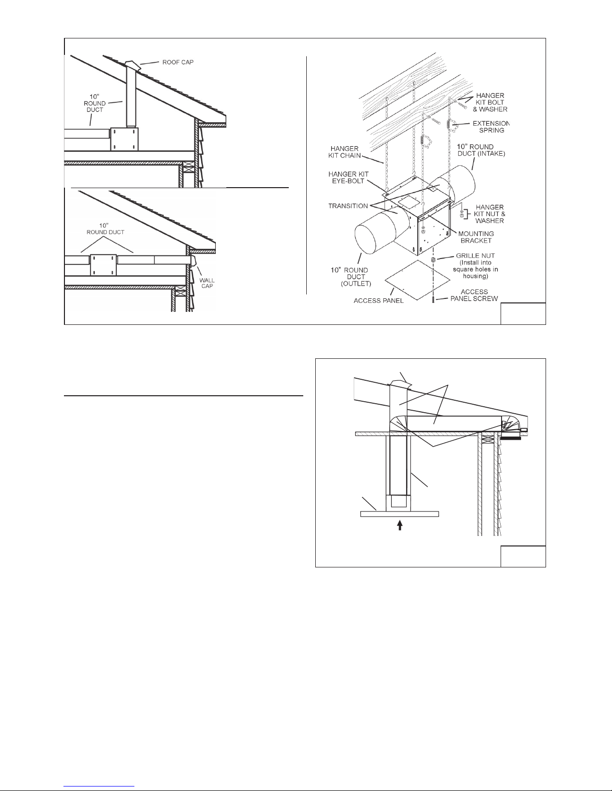
6. Ducted fans must always be vented to the outdoors.
7. Do not use this unit with any separate solid-state speed control device.
8. To reduce the risk of fire, use only steel ductwork.
GROUNDING INSTRUCTIONS
This appliance must be grounded. In the event of an electrical short circuit, grounding reduces the risk
of electrical shock by providing an escape wire for the electric current.
WARNING - Improper grounding can result in a risk of electric shock.
Consult a qualified electrician if the grounding instructions are not completely understood, or if doubt
exists as to whether the appliance is properly grounded.
Do not use an extension cord. Have a qualified electrician install an outlet near the appliance.
TO REDUCE THE RISK OF A RANGE TOP GREASE FIRE:
A. Never leave surface units unattended at high settings. Boilovers cause smoking and greasy
spillovers that may ignite. Heat oils slowly on low or medium settings.
B. Always turn hood ON when cooking at high heat or when flambeing food (i.e. Crepes Suzette,
Cherries Jubilee, Peppercorn Beef Flambe’).
C. Clean ventilating fans frequently. Grease should not be allowed to accumulate on fan or filter.
D. Use proper pan size. Always use cookware appropriate for the size of the surface element.
!
INTENDED FOR DOMESTIC COOKING ONLY
!

- 4 -
WARNING
TO REDUCE THE RISK OF INJURY TO PERSONS IN THE EVENT OF A RANGE TOP GREASE
FIRE, OBSERVE THE FOLLOWING:*
1. SMOTHER FLAMES with a close-fitting lid, cookie sheet, or metal tray, then turn off the burner. BE
CAREFUL TO PREVENT BURNS. If the flames do not go out immediately, EVACUATE AND CALL
THE FIRE DEPARTMENT.
2. NEVER PICK UP A FLAMING PAN - You may be burned.
3. DO NOT USE WATER, including wet dishcloths or towels - violent steam explosion will result.
4. Use an extinguisher ONLY if:
A. You know you have a Class ABC extinguisher and you already know how to operate it.
B. The fire is small and contained in the area where it started.
C. The fire department is being called.
D. You can fight the fire with your back to an exit.
* Based on “Kitchen Fire Safety Tips” published by NFPA.
!
CAUTION
1. For indoor use only.
2. To reduce risk of fire and to properly exhaust air, be sure to duct air outside. Do not vent exhaust
air into spaces within walls or ceilings or into attics, crawl spaces, or garages.
3. Take care when using cleaning agents or detergents.
4. Avoid using food products that produce flames under the Range Hood.
5. For general ventilating use only. Do not use to exhaust hazardous or explosive materials and
vapors.
6. To avoid motor bearing damage and noisy and/or unbalanced impellers, keep drywall spray,
construction dust, etc. off power unit.
7. Your hood motor has a thermal overload which will automatically shut off the motor if it becomes
overheated. The motor will restart when it cools down. If the motor continues to shut off and restart,
have the hood serviced.
8. For best capture of cooking impurities, the bottom of the hood should be a minimum of 24" and a
maximum of 36" above the cooking surface.
9. Two installers are recommended because of the large size and weight of this hood.
10. This product is equipped with a thermostat which may start blower automatically. To reduce the
risk of injury and to prevent power from being switched on accidentally, switch power off at service
panel and lock or tag service panel.
11. Please read specification label on product for further information and requirements.
12. EXTERNAL BLOWER MODELS ONLY: To reduce risk of fire and electric shock, install this range
hood only with Best Exterior Blower Models EB6, EB9, EB12 or EB15 or Best In-Line Blower
Models ILB3, ILB6, ILB9 or ILB11. Other blowers cannot be substituited. (Blower sold separately)

- 5 -
LED LAMPS
The hood is provided with LED lamps wich require no maintenance.
CLEANING AND MAINTENANCE
Proper maintenance of the Range Hood will assure proper performance of the unit.
Motor
The motor is permanently lubricated and never needs oiling. If the motor bearings make
excessive or unusual noise, replace the motor with the exact service motor. The impeller
should also be replaced.
Grease Filter
The grease filters should be cleaned frequently. Use a warm detergent solution. Grease
filter are dishwasher safe.
Clean all-metal filters in the dishwasher using a non-phosphate detergent. Discoloration
of the filter may occur if using phosphate detergents, or as a result of local water
conditions - but this will not affect filter performance. This discoloration is not covered by
the warranty. See “INSTALL FILTERS” section for removal and installation instructions.
Non-ducted Recirculation Filter
The non-ducted recirculation filter should be changed every 6 months. Replace more
often if your cooking style generates extra grease, such as frying and wok cooking. See
“INSTALL FILTERS” section for removal and installation instructions.
Stainless Steel Cleaning
DO:
• Regularly wash with clean cloth or rag
soaked with warm water and mild soap or
liquid dish detergent.
• Always clean in the direction of original
polish lines.
• Always rinse well with clear water (2 or 3
times) after cleaning. Wipe dry completely.
• You may also use a specialized
household stainless steel cleaner.
DON’T:
• Use any steel or stainless steel wool or
any other scrapers to remove stubborn dirt.
• Use any harsh or abrasive cleansers.
• Allow dirt to accumulate.
• Let plaster dust or any other construction
residues reach the hood. During
construction/renovation, cover the range
hood to make sure no dust sticks to the
stainless steel surface.
Avoid: When choosing a detergent
• Any cleaners that contain bleach will attack stainless steel
• Any products containing: chloride, fluoride, iodide, bromide will deteriorate surfaces rapidly.
• Any combustible products used for cleaning such as acetone, alcohol, ether, benzol,
etc., are highly explosive and should never be used close to a range.

- 6 -
OPERATION
The hood is operated using the (5) push buttons located on the front edge of the hood. The
Light On/Off buttons turn the lights on and off.
The Blower Off / - button decreases the blower speed each time pressed. Depress and
hold the button for 2 seconds to turn the blower off.
The Blower On /+ button turns the blower on and increases the blower speed each time
pressed. There are four different speed settings: Low, Medium-Low, Medium-High and High.
The Blower LED Indicators illuminate to indicate the selected blower speed.
The Delay button activates the delay-off feature. When the blower in on and the button is
pushed, the blower will continue to operate at the current speed setting for 10-minutes
before automatically turning itself off. The LED (on the right) flashes during operation.
The LED (on the right) is also used as a filter clean reminder. It will flash after 30 hours of
operation - indicating the need to clean the filters.
The Filter Clean Reset button is used to reset the 30-hour filter timer. After filters are
cleaned or replaced, press button once to reset the filter clean alarm.
Auto Shut-Off Feature
If the blower and/or the lights are on continuously for 10 hours without any user interaction
with the controls, the hood will automatically shut off. Press any control button to re-activate
the hood.
HEAT SENTRY™
Your hood is equipped with a HEAT SENTRY™ thermostat. This thermostat is a device that
will turn on or speed up the blower if it senses excessive heat above the cooking surface.
1) If blower is OFF - it turns blower ON to HIGH speed.
2) If blower is ON at a lower speed setting - it turns blower up to HIGH speed.
When the temperature level drops to normal, the blower will return to its original setting.
WARNING
The HEAT SENTRY thermostat can start the blower even if the hood is turned OFF.
When this occurs, it is impossible to turn the blower OFF with its switch. If you must
stop the blower, do it from the main electrical panel.
Controls (Fig.1)

- 7 -
PREPARE THE HOOD
Unpack hood and check contents.
You should receive:
1 - Hood
1 - Decorative Flues
1 - Support Frame
1 - Parts Bag (B080811002) containing:
30 - Mounting Screws (3,9 x 9,5mm Pan Head)
6 - Mounting Lag Screws (6 x 60mm)
4 - Washers ø 6.4x12.5mm
1 - Damper Kit
4 - Mounting Screws (3,9 x 9,5mm Pan Head)
1 - Installation Instructions
DAMPER KIT
DECORATIVE
FLUES
30 MOUNTING
SCREWS (3,9x9,5mm
Pan Head) 6 MOUNTING LAG
SCREWS (6x60mm) FIG. 2
10 WASHERS
Ø 6.4x12.5mm
SUPPORT
FRAME 4 MOUNTING
SCREWS (3,9x9,5mm
Pan Head)

- 8 -
EXTERIOR AND IN-LINE BLOWER SELECTION IC34E Series
CAUTION: To reduce risk of fire and electric shock, install this range hood only with Best
Exterior Blower Models EB6, EB9, EB12 or EB15, and Best In-Line Blower Models ILB3, ILB6,
ILB9 or ILB11. Other blowers cannot be substituited.
The blower must be UL listed for Canadian and U.S. use, and evaluated for use with solid state
speed control, rated 120V, 60 Hz, 6.0 A max.
INSTALL THE DUCTWORK IC34E Series
NOTE: To reduce the risk of fire, use only metal ductwork.
1. Choose the location where the Exterior Blower or In-Line Blower will be mounted. See
illustrations below for mounting location suggestions and restrictions.
2. A straight, short duct run will allow the hood to perform most efficiently.
3. Long duct runs, elbows and transitions will reduce the performance of the hood. Use as
few of them as possible. Larger ducting may be required for best performance with long
duct runs.
4. After the Exterior or In-Line Blower has been installed, connect round metal ductwork
and work back towards the hood location. Use duct tape to seal joints between ductwork
sections.
10”ROUND
DUCT
24” TO 36” ABOVE
COOKING SURFACE
DECORATIVE
FLUE
10” ROUND
DUCT EXTERIOR
BLOWER
HOOD
OK
OK
SUGGESTED MOUNTING LOCATIONS
EXTERIOR BLOWER
CAUTION: MAY NOT FIT
UNDER EAVES OF SINGLE
STORY HOMES
FIG. 3

- 9 -
IN-LINE BLOWER
FIG. 4
INSTALL THE DUCTWORK
IC34IQ Series
WARNING: To reduce the risk of fire, use
only metal ductwork.
1. Decide where the ductwork will run
between the hood and the outside.
2. A straight, short duct run will allow the hood
to perform most efficiently.
3. Long duct runs, elbows, and transitions will
reduce the performance of the hood. Use
as few of them as possible.
4. Install a roof or wall cap. Connect 10" round
metal ductwork to cap and work back
towards hood location. Use duct tape to
seal the joints between ductwork sections.
ROOF CAP
10” ROUND
ELBOW
24” TO 36” ABOVE
COOKING SURFACE
10” ROUND
DUCT
DECORATIVE
FLUE
HOOD
FIG. 5

- 10 -
INSTALL SUPPORT SYSTEM
1. At hood location, install 2 x 4 or larger cross
framing between ceiling joists using
dimensions shown.
2. Finish the ceiling surface. Be sure to mark
the location of the ceiling joists and cross
framing.
3. Adjust the overall height using the chart below
of the support frame. Loosen and re-tighten
the 4 screws in the height adjustment slots
as necessary. Insert 12 screws (3.9x9.5mm)
located in the Hardware Package (Fig.6)
make sure this a 4” min. overlap between the
upper and lower support legs.
4. Mount the four 6x70mm screws to ceiling in
the location shown in figure 7. Allow 1/4”
clearance between screw head and ceiling
(screws will be tightened later). Make sure
the screws are driven into the center of joists
and framing for maximum strength.
Notes:
a. “-” = Mounting height is not possible.
b. Minimum hood distance above cook top
must not be less than 24”. A maximum of
36” above cook top is highly recommended
for best capture of cooking impurities.
Distances over 36” are at the installer and
the users discretion; and if ceiling height
and flue lenght permit.
c. Requires optional 10 / 11’ flue extension,
ducted model AEIC345SB or non-ducted
model AEIC345SBN.
TOP VIEW OF SUPPORT FRAME
103/16” (260mm)
117/16”
(290mm)
CEILING
JOISTS
CROSS FRAMING
SUPPORT
FRAME
10 3/16”
DRYWALL
MOUNTING
SCREWS
(6x70mm)
HEIGHT ADJUSTMENT
SLOTS
==
11” (280mm)
FIG. 6
FIG. 7
MOUNTING
SCREWS
3,9x9,5mm
Ceiling
Height
Hood Distance Above 36” High Cook Top (in.)
8 Feet
24 25 26 28 29 30 31 32 33 34 35 3627
Assembled Support Frame Height (in.)
Duct
Method
Ducted
Non-
Ducted
Ducted
Non-
Ducted
Ducted
Ducted
9 Feet
11 Feet (c)
10 Feet (c)
- - - - - - - - XXX XX
-XXXXXXXXXXXX
XXXXXXXXXXXXX
-X*X*X*X*XXXXXXXX
XXXX------- --
X X X X -(a) - - - - - - - -
* = Non duct openings exposed

- 11 -
INSTALL THE HOOD
DUCTEDANDNON-DUCTEDINSTALLATION
1. Remove the electrical system box from
chimney frame by removing (2) 3.9 x 9.5
mm screws (Fig. 8).
2. Attach electrical system box to frame using
(2) 3.9 x 9.5 mm screws removed in Step
1 and (2) 3.9 x 9.5 mm screws and (2) lock
washers from hardware bag (Fig.9)
3. Fix the damper kit onto the hood using 4
screws (3.9x9.5mm) located in the
Hardware Package (Fig.10).
FIG.9
MOUNTING
SCREWS
3,9x9,5mm
FIG.8
MOUNTING SCREWS 3,9x9,5mm
FIG.10
MOUNTING SCREWS 3,9x9,5mm

- 12 -
CONNECT DECORATIVE FLUE
DUCTED INSTALLATION ONLY
Note: Rooms with 10 or 11 foot ceilings
require flue extension model AEIC34SB,
available from your local dealer. Discard
the upper flue supplied with the range
hood and replace it with the longer flue
extension.
1. Insert the upper flue and lower flue in the
support frame (Fig.11).
2. Attach upper flue temporarily to the support
frame with the mounting screws 3.9x9.5 mm,
slide the lower flue onto the support frame
and tape to hold in place (Fig.12).
3. Mount the hood to the ceiling using the (4)
previously installed 6x70mm screws.
Tighten these screws. Install (2) additional
6x70mm screws as shown in the
illustration. Make sure all (6) screws are
secure.
4. Secure the hood to the ceiling and install
the (2) additional screws (6x70mm).
5. Use 8" round metal duct to connect the
duct collar on the hood to the ductwork
above (Fig.13).
6. Use duct tape to make all joints secure and
air tight.
INSTALL THE HOOD
DUCTEDANDNON-DUCTEDINSTALLATION
1. Adjust the overall height of the support
frame. Loosen and re-tighten the 4 screws
in the height adjustment slots as
necessary. Insert 16 screws (3.9x9.5mm),
and 8 washers (D.6.4x12.5mm) located in
the Hardware Package (Fig.14).
FIG.11
FIG.12
FIG.13
8-INCH DIA.
METAL DUCT
INSTALL (16)
3.9 x 9.5 mm
SCREWS &
LOCK WASHERS
ON (8) SCREWS
FIG.14
MOUNTING
SCREWS
3.9 x 9.5 mm

- 13 -
NON-DUCTED INSTALLATION ONLY
Note:
a. Purchase Model ANKWC45 Non-ducted
Recirculation Kit from your local dealer.
b. Rooms with 10 or 11 foot ceilings require
flue extension model AEIC34SBN,
available from your local dealer. Discard
the upper flue supplied with the range hood
and replace it with the longer flue extension.
1. Install discharge collar supplied with the
range hood (Fig.15).
2. Attach the 6”-to-8” adapter to blower
discharge and tape joint with aluminum
duct tape (Fig.15).
3. Insert the plenum in the upper support
frame. Make sure that the letter F is
positioned at the front of the support frame
(Fig.16).
4. Install the plenum to the upper decorative
flue using (2) 3.9 x 9.5 mm screws
provided as shown (Fig.17).
5. Attach 6-inch expandable ducting to the
plenum and tape joint with aluminum duct
tape (Fig.18).
MOUNTING SCREWS
(3.9 x 9.5 mm Flat Head)
FIG. 15
FIG. 18
DUCT
CONNECTOR
FIG. 17
FIG. 16
FRONT
EXPANDABLE
DUCT

- 14 -
WIRING(IC34IQ)
Note: This range hood must be properly
grounded. The unit should be installed by a
qualified electrician in accordance with all
applicable national and local electrical
codes.
1. Remove the wiring box cover. Remove a
knockout from the wiring box (Fig.19).
2. Secure the conduit to the wiring box
through a conduit connector.
3. Make electrical connections. Connect white
to white, black to black and green to green.
4. Replace wiring box cover and screws. Make
sure that wires are not pinched between
cover and box.
ADDITIONAL EXTERNAL
BLOWER WIRING (IC34E)
1. Run 2-wire plus ground power cable from
the exterior blower to the hood’s wiring
box marked “motor connection” (Fig.20).
2. Remove the cover from the wiring box and
remove one knockout.
3. Feed 6” of cable through the knockout
opening and secure the cable to the wiring
box with an appropriate connector.
4. Make electrical connections at the hood.
Connect white-to-white, red-to-black and
green-to-ground.
5. Replace the wiring box cover and screws.
Make sure wires are not pinched between
the cover and box.
Exterior blower connection:
1. Make electrical connections at the exterior
blower (see instructions provided with the
exterior blower).
CONNECT DECORATIVE FLUE
1. Lower the lower flue in place (Fig.21)
WIRING BOX
COVER
FIG.19
EXTERIOR BLOWER
BLOWER CONNECTION AT HOOD
CONNECT:
WHITE-TO-WHITE,
RED-TO-BLACK,
GREEN-TO-GROUND.
BOX MARKED
“MOTOR
CONNECTION”
FIG.20
FIG. 21

- 15 -
FIG. 22
FIG. 23
INSTALL FILTERS
DUCTED AND NON-DUCTED HOODS
NOTE: prior to use, remove protective film
from the filter frame.
1. To remove the GREASE filter, pull down
on latch tab to disengage the filter from
the hood. Tilt the filter downward and
remove (Fig.22).
2. To install the GREASE filter, align rear
filter tabs with slots in the hood. Pull
latch tab down. Push filter into place and
release tab. Make sure the filter is
securely engaged after installation.
NON-DUCTED HOODS ONLY
1. To remove the CHARCOAL filter, grip and
push filter tab toward rear of hood. Pull
the filter down to disengage the rear filter
tabs (Fig.23).
2. To install the CHARCOAL filter, align filter
in rectangular opening. Push filter against
springs in rear of hood and press into
place. Make sure the filter is securely
engaged after assembly.
3. Install GREASE filter after charcoal filter
is installed.
4. The charcoal filter replacement model is
AFCWC345.

- 16 -
CALIBRATE IQ BLOWER SYSTEMTM Ducted Internal Blower Hoods Only
After the hood is installed and wired, engage the calibration process (our Guaranteed
Performance System Technology) to ensure full-rated airflow is being delivered. Prior to
calibration, ensure that all filters, light bulbs and duct system components are installed and
sealed.
CALIBRATION PROCESS
Hold the calibration button for 3 seconds; calibration button will light up and stay on for up to
13 minutes. The blower will start and begin the calibration process. When calibration is
complete, one of two things will occur:
A.The blower turns off and calibration button light turns off = Successful calibration.
B.The blower turns off and calibration button light blinks continuously = Too much restriction
in the ductwork is preventing the IQ Blower SystemTM from achieving the rated airflow. The
blower is automatically set to maximum intensity.
Note: Common items that cause restrictions: restricted damper flap (backdraft damper, wall
cap, roof cap), too many elbows, duct size less than 80% of hood outlet, poor transition,
use of flex ducting and/or crushed ducting.
Two options are available:
1.Press thecalibrationbutton to acceptairflowasis. The IQBlowerSystemTM is now configured
to its highest possible setting. The blinking calibration light goes out.
2.Correct duct restriction and repeat the calibration process.
a. To clear the original calibration data, hold calibration button for 10 seconds. The light
will blink 3 times to confirm and the blower configuration will go back to default settings.
b. Repeat calibration process.
CALIBRATION LIGHT
CALIBRATION
BUTTON

- 17 -
EXTERNAL BLOWER
PROGRAMMING MODE PROCEDURE (IC34E)
The range hood is designed to work with
several different blower models. Before using,
the control must first be programmed to your
blower model, in order to achieve proper
operating speeds.
From the chart below:
1. Find the SETUP number that corresponds
to the blower model that is installed with
your range hood.
2. The control is factory-preset to SETUP 3. If
your blower model is listed under SETUP
3, no programming is required and the
range hood is ready to use.
3. To program blower models listed under
SETUP 1 and 2:
A) Power must be supplied to the hood.
The blower and lights must be turned
off.
B) Press and hold OFF and ON/+ for 5
seconds. The Blower LED Indicators
will flash 3 times. Then only the LED
will stay lit. After 1 second, the Blower
LED Indicators will show the current
setting as follows:
SETUP 1
SETUP 2
SETUP 3
C) To select the proper SETUP:
Press OFF- or ON/+ to select the desired
SETUP.
D) Once the proper SETUP is found:
Press ON to memorize the setting, or
wait 15 seconds and the program will
automatically exit and store the SETUP.
E) The range hood is now ready to use.
SETUP 1
BLOWER
MODEL
NUMBER
EB6
ILB3
ILB6
EB12
EB15
ILB9
EB9
ILB11
SETUP 2 SETUP 3
(default)

- 18 -
WARRANTY
ONE YEAR LIMITED WARRANTY FOR BEST PRODUCTS
Broan-NuTone LLC (Broan-NuTone) warrants to the original consumer purchaser of Best products that such products will be free
from defects in materials or workmanship for a period of one year from the date of original purchase. THERE ARE NO OTHER
WARRANTIES, EXPRESS OR IMPLIED, INCLUDING, BUT NOT LIMITED TO, IMPLIED WARRANTIES OR MERCHANT ABILITY
OR FITNESS FOR A PARTICULAR PURPOSE.
During this one-year period, Broan-NuTone will, at its option, repair or replace, without charge, any product or part which is found
to be defective under normal use and service.
THIS WARRANTY DOES NOT EXTEND TO FLUORESCENT LAMP STARTERS, TUBES, HALOGEN AND INCANDESCENT
BULBS, FUSE, FILTERS, DUCTS, ROOF CAPS, WALL CAPS AND OTHER ACCESSORIES FOR DUCTING. This warranty does
not cover (a) normal maintenance and service or (b) any products or parts which have been subject to misuse, negligence,
accident, improper maintenance or repair (other than by Broan-NuTone), faulty installation or installation contrary to recom-
mended installation instructions.
The duration of any implied warranty is limited to the one-year period as specified for the express warranty. Some states do not
allow limitation on how long an implied warranty lasts, so the above limitation may not apply to you.
BROAN-NUTONE'S OBLIGATION TO REPAIR OR REPLACE, AT BROAN-NUTONE'S OPTION, SHALL BE THE PURCHASER'S
SOLE AND EXCLUSIVE REMEDY UNDER THIS WARRANTY. BROAN-NUTONE SHALL NOT BE LIABLE FOR INCIDENTAL,
CONSEQUENTIAL OR SPECIAL DAMAGES ARISING OUT OF OR IN CONNECTION WITH PRODUCT USE OR PERFORMANCE.
Some states do not allow the exclusion or limitation of incidental or consequential damages, so the above limitation or exclusion
may not apply to you.
This warranty gives you specific legal rights, and you may also have other rights, which vary from state to state. This warranty
supersedes all prior warranties.
To qualify for warranty service, you must (a) notify Broan-NuTone at the address stated below or telephone number stated below,
(b) give the model number and part identification and (c) describe the nature of any defect in the product or part. At the time of
requesting warranty service, you must present evidence of the original purchase date.
In USA - Best®, 926 W. State Street, Hartford, WI 53027 (800-558-1711)
In Canada - Best®, 550 Lemire Blvd., Drummondville, QC J2C 7W9 (866-737-7770)
www.BestRangeHoods.com

- 19 -
KEY NO. PART NO. DESCRIPTION
9 B08087679 Grease Filters
17 BE3351998 Light Diffuser Support
37 B02300804 Heat Sentry
67 B06102619 Wires Assembly
76 B003102891 Glass Front Trim
114 B03292499 Runner Wires
115 BE3350233 Wiring Box
116 BE3334252 Wiring Box Cover
124 B08092904 Telescopic Structure Bottom
125 B08093457 Telescopic Structure Top
130 B08092983 Glass Trim Back
202 B03292290 Wire Clamp
415 B03292596 Fairlead
439 B02320034 Grommet
474 B08093413 Led Lamp
477 BE3352074 Light Diffuser Support Back
485 B08016376 Decorative Flue Assembly
506 97019431 BLDC Driver
507 B06102584 Calibration Button Assembly
AQI B06102594 Switch Box Assembly
ARU B080810849 Duct Connector Assembly 10”
IME B06145225 Electrical Installation Assembly
CAS B06002259 Blower Assembly
* B080811002 Fitting Set
* Not shown assembled.
SERVICE PARTS
MODEL IC34IQ

- 20 -
Table of contents
Languages:
Other Best Ventilation Hood manuals

Best
Best IP29M Series User manual

Best
Best KB 300 User manual

Best
Best IPP9E42S User manual

Best
Best Pro-Style UP26 Series User manual

Best
Best CP35 Series User manual

Best
Best IS170 User manual

Best
Best U102I User manual

Best
Best CC34E63SB User manual

Best
Best Range Hood U102E User manual

Best
Best K260A series User manual
Popular Ventilation Hood manuals by other brands

Whirlpool
Whirlpool RH2600XL-1 SERIES installation instructions

EuropAce
EuropAce Otimmo ECH 5141S manual

KKT KOLBE
KKT KOLBE DUALE-V2 user manual

Faber
Faber Cristal 24 SS Installation instructions; use and care information

ELICA
ELICA Pilato EPL636S1 Use, care and installation guide

Vortice
Vortice VORTEX 90-I installation manual