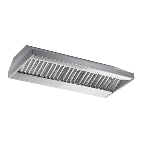
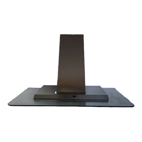
Best P195ES70SB User manual

- 1 -
In USA - BEST Hartford, Wisconsin
In CANADA - BEST Drummondville, QC, Canada
REGISTER YOUR PRODUCT ONLINE AT : www.BestRangeHoods.com/register
For additional Information visit www.BestRangeHoods.com
ENGLISH.........................................3
FRANÇAIS......................................12
ESPAÑOL.......................................21
Power Module
Module de Puissance
Módulo de potencia
Mod. P195ES70SB

- 2 -

- 3 -
READ AND SAVE THESE INSTRUCTIONS
WARNING
TO REDUCE THE RISK OF FIRE, ELECTRIC SHOCK, OR INJURY TO PERSONS, OB-
SERVE THE FOLLOWING:
1. Use this unit only in the manner intended by the manufacturer. If you have questions,
contact the manufacturer at the address or telephone number listed in the warranty.
2. Before servicing or cleaning unit, switch power off at service panel and lock service panel
to prevent power from being switched on accidentally. When the service disconnecting
means cannot be locked, securely fasten a prominent warning device, such as a tag, to the
service panel.
3. Installation work and electrical wiring must be done by a qualified person(s) in accordance
with all applicable codes and standards, including fire-rated construction codes and stan-
dards.
4. Sufficient air is needed for proper combustion and exhausting of gases through the
flue (chimney) of fuel burning equipment to prevent backdrafting. Follow the heating
equipment manufacturer’s guidelines and safety standards such as those published by
the National Fire Protection Association (NFPA), and the American Society for Heating,
Refrigeration and Air Conditioning Engineers (ASHRAE), and the local code authorities.
5. When cutting or drilling into wall or ceiling, do not damage electrical wiring and other
hidden utilities.
6. Ducted fans must always be vented to the outdoors.
7. Do not use this unit with any separate solid-state speed control device.
8. To reduce the risk of fire, use only metal ductwork.
9. This unit must be grounded.
!
INTENDED FOR DOMESTIC COOKING ONLY
!

- 4 -
!
CAUTION
1. For indoor use only.
2. To reduce risk of fire and to properly exhaust air, be sure to duct air outside. Do not vent
exhaust air into spaces within walls or ceilings or into attics, crawl spaces, or garages.
3. Take care when using cleaning agents or detergents.
4. Avoid using food products that produce flames under the Range Hood.
5. For general ventilating use only. Do not use to exhaust hazardous or explosive materials
and vapors.
6. To avoid motor bearing damage and noisy and/or unbalanced impellers, keep drywall
spray, construction dust, etc. off power unit.
7. Your hood motor has a thermal overload which will automatically shut off the motor if it
becomes overheated. The motor will restart when it cools down. If the motor continues
to shut off and restart, have the hood serviced.
8. For best capture of cooking impurities, the bottom of the hood should be a minimum of
24” and a maximum of 30” above the cooking surface.
9. Use with approved cord-connection kit only.
10. Please read specification label on product for further information and requirements.
11. Do not operate any fan with a damaged cord or plug. Discard fan or return to
an authorized service facility for examination and/or repair.
WARNING
TO REDUCE THE RISK OF A RANGE TOP GREASE FIRE:
A. Never leave surface units unattended at high settings. Boilovers cause smoking and
greasy spillovers that may ignite. Heat oils slowly on low or medium settings.
B. Always turn hood ON when cooking at high heat or when cooking flaming foods. (i.e.
Crepes Suzette, Cherries Jubilee, Peppercorn Beef Flambe’).
C. Clean ventilating fans frequently. Grease should not be allowed to accumulate on fan or
filter.
D. Use proper pan size. Always use cookware appropriate for the size of the surface element.
TO REDUCETHE RISK OF INJURY TO PERSONS INTHE EVENT OF A RANGETOP
GREASE FIRE, OBSERVE THE FOLLOWING:*
1. SMOTHER FLAMES with a close-fitting lid, cookie sheet, or metal tray, then turn
off the burner. BE CAREFUL TO PREVENT BURNS. If the flames do not go out
immediately, EVACUATE AND CALL THE FIRE DEPARTMENT.
2. NEVER PICK UP A FLAMING PAN - You may be burned.
3. DONOTUSEWATER,includingwetdishclothsortowels-violentsteamexplosionwillresult.
4. Use an extinguisher ONLY if:
A. You know you have a Class ABC extinguisher and you already know how to operate it.
B. The fire is small and contained in the area where it started.
C. The fire department is being called.
D. You can fight the fire with your back to an exit.
* Based on “Kitchen Fire Safety Tips” published by NFPA.

- 5 -
PREPARE THE HOOD
Unpack hood and check contents.
1 - Hood
1 - Hardware Bag (B08084043) containing:
4 - Mounting Screws (4,2 x 15mm Pan Head)
1 - Installation Instructions
1 - Parts Bag (B080810849) containing:
4 - Mounting Screws (3,9 x 9,5mm Pan Head)
1 - 8” Damper Duct Connector
4 MOUNTING SCREWS
(4,2 x 15mm Pan Head)
!
CAUTION
Wearsafetyglovesbeforeeveryinstallationand/
or manitenance operation
DAMPER DUCT CONNECTOR
(B08092501)
4 MOUNTING SCREWS
(3,9 x 9,5mm Pan Head)

- 6 -
AIR
AIR
GRILL
8” ROUND
DUCT AND
ELBOW
DAMPER DUCT
CONNECTOR
HOOD
At least
15”
INSTALL THE DUCTWORK (Ducted Hoods Only) -Fig.1
NOTE: To reduce the risk of fire, use only metal ductwork.
1. Decide where to install the duct.
The ducting from this fan to the outside of the building has a strong effect on the
air flow, noise and energy use of the fan. Use the shortest, straightest duct routing
possible for best performance, and avoid installing the fan with smaller ducts than
recommended. Insulation around the ducts can reduce energy loss and inhibit mold
growth. Fans installed with existing ducts may not achieve their rated airflow
2. Use duct tape to seal the joints between ductwork sections.
3. Install a roof or wall cap. Connect 8” round metal ductwork to cap and work back
towards hood location.
DUCTED
CONFIGURATION
ROOF CAP
8” ROUND
DUCT
WALL
CAP
HOOD
24” TO 30” ABOVE
COOKING SURFACE
8” ROUND
ELBOW
INSTALL DUCT CONNECTOR
1. Install damper duct connector onto the hood using (4) mounting screws that are
provided (3,9mm. x 9,5mm.).
2. Remove the tape located on the damper.
Fig.1
Fig. 2
NON-DUCTED CONFIGURATION
INSTALL THE DUCTWORK (Non-Ducted Hoods Only) -Fig.2
NOTE: The following material must be purchased separately for non-ducted recir-
culation installation.
• Non-ducted Charcoal Filter Model: ROUND-
FILTER
• 8” round metal ductwork and fittings.
• Grill
1. Attach 8” round metal ductwork and fittings.
2. Run ductwork to the location where it is dis-
charged back into the room.
3. Duct tape all joints to make them secure and
air tight.
4. Install a decorative grill. You may need to pur-
chase a metal round-to-rectangular transition,
depending on your application.

- 7 -
HOOD
33-7/16”
(85cm.)
MAX.
INSTALL THE HOOD
Note: The hood must be installed
inside the cabinet.
The internal height of cabinet must be
minimum 16”.
The hood should be mounted cen-
tered over the cook top burners.
1. Remove the frame by moving the 2
slide fasteners “A” forward (Fig.4 ).
Push the filter latch and tilt the filter
downward (B) and remove.
2. Cut a hole in the bottom of the cabinet,
using the dimensions shown (Fig.5 ).
3. Adjust the position of the clasping side
spring by turning the “D” screw accord-
ing to the thickness of the cabinet to
which it is going to be anchored (Fig.6).
4. Insert the hood in the cabinet (Fig.7 )
and lock into position using the side
spring.
5. Secure the hood with (4) “C” mounting
screws.
6. Replace the frame by moving the 2 slide
fasteners “A” backward. (Fig.4 ).
Fig. 4
26-9/16
10-¼”
1”
Fig. 5
X= min 7/16”
max 13/16”
CLASPING SIDE
SPRING
X
Fig.6
D
Fig.7
WIRING
Note:This range hood must be pro-
perly grounded. The unit should be
installed by a qualified electrician in
accordance with all applicable na-
tional and local electrical codes.The
grounded 3 prong outlet should be
accessible after the hood installation
(i.e.: access door).
GROUNDING INSTRUCTIONS
This appliance must be grounded. In the
eventofanelecticalshortcircuit,grounding
reducesthe riskofelectric shockby provi-
dinganescapewirefortheelectriccurrent.
This appliance is equipped with a cord
havinga grounding wire with agrounding
plug.Theplugmustbypluggedintoanout-
letthatis properlyinstalled andgrounded.
WARNING-Impropergroundingcanresult
in a risk of electric shock.
Consulta qualifiedelectricianif thegroun-
ding instructions are not completely un-
derstood,or if doubt exist asto wheter the
appliance is properly grounded. Do not
usean extensioncord.If thepower supply
cordistooshort,haveaqualifiedelectrician
installanoutletneartheappliance.Position
thepowersocketatamaximumdistanceof
33-7/16”(85cm.)from where theleadexits
fromthe hood(see illustrationalongside).
Fit the plug into the power socket.
CONNECT DUCTWORK
1. Use 8” round metal duct to connect
the duct connector on the hood to the
ductwork above.
2. Use duct tape to make all joints se-
cure and air tight.

- 8 -
01 0123
INSTALL FILTERS
(NON-DUCTED HOODS ONLY) - Fig.8
1. Install a charcoal filter on each side of
the blower (included with Non-ducted
Charcoal Filter Model: ROUNDFILTER
2. To install the charcoal filter, align center
keyhole slot on the filter with center of the
blower. Rotate to lock filter into place.
3.Toremovethecharcoalfilter,rotatethefilter
until it disengages from the blower.
(DUCTED AND NON-DUCTED HOODS)
• To remove the GREASE filter, grip the
latch tab and pull it down. This will dis-
engange the filter from the hood.
• ToinstalltheGREASEfilter,alignfiltertabs
to the side of the filter with slots in the
hood drawer. Pull latch tab down, push
filter up into place and release the tab.
• Makesure thefilteris securelyenganged
after assembly.
Fig.8
NON-DUCTED RECIRCULATION
FILTERS
MAINTENANCE
ALWAYS SWITCH OFF THE ELECTRICITY
SUPPLY BEFORE CARRYING OUT ANY
OPERATIONS ONTHE APPLIANCE.
Grease Filters
The grease filter should be cleaned fre-
quently. Use a warm detergent solution.
Grease filter is dishwasher safe.
To remove the grease filter: push in on the
metal latch tab. Tilt the filter downward and
remove.
Cleaning
Occasional care will help preserve its fine
appearance.
• Clean with warm water and mild detergent
only.
•Followallcleaningbyrinsingwithclearwater.
• Wipe dry with clean, soft cloth.
Light bulbs
Thisrangehoodrequirestwo13wattG24q-1
Compact Fluorescent lamps (included). To
change bulbs (Fig.9):
1. Remove the frame by moving the 2 slide
fasteners (A) (Fig.4, page 6).
2. Toreplacelamp,grasplampatbaseandpull
outtoremove.Replacewith13WFluores-
cent lamp noted above.
CAUTION: BULB MAY BE HOT!
Fig.9
OPERATION - Fig.10
Controls
The light switch turns the lamps on
and off.
The blower switch: makes it possible to
select the motor operating speed (3
speeds).
Position 0: motor off.
The pilot lamp lights up whenever the
blower is on.
LIGHT
SWITCH BLOWER
SWITCH
PILOT LAMP Fig.10

- 9 -
HEAT SENTRY™
Your hood is equipped with a HEAT SENTRY™ thermostat. This thermostat is a
device that will turn on or speed up the blower if it senses excessive heat above the
cooking surface.
1) If blower is OFF - it turns blower ON to HIGH speed.
2) If blower is ON at a lower speed setting - it turns blower up to HIGH speed.
Whenthetemperature leveldropsto normal,the blower willreturn to itsoriginal setting.
WARNING
The HEAT SENTRY thermostat can start the blower even if the hood is turned
OFF.When this occurs, it is impossible to turn the blower OFF with its switch.
If you must stop the blower, do it from the main electrical panel.

- 10 -
Limited Warranty
Warranty Period and Exclusions: Broan-NuTone, LLC(the “Company”) warrants to the consumer purchaser of its product (“you”) that the
product (the “Product”) will be free from material defects in the materials or its workmanship for a period of five (5) years from the date of
original purchase (or such longer period as may be required by applicable law) or a period of two (2) years from the date of service for any
labor provided on the Product.
The limited warranty period for any replacement parts provided by the Company and for any Products repaired or replaced under this limited
warranty shall be the remainder of the original warranty period (or such longer period as may be required by applicable law).
THIS WARRANTY DOES NOT EXTEND TO FLUORESCENT LAMP STARTERS, TUBESAND BULBS, FUSES, FILTERS, DUCTS, ROOF
CAPS, WALL CAPS AND OTHER ACCESSORIES FOR DUCTING. This warranty does not cover (a) normal maintenance and service, (b)
normal wear and tear, (c) any Products or parts which have been subject to misuse, abuse, abnormal usage, negligence, accident, improper
or insufficient maintenance, storage or repair (other than repair by the Company), (d) damage caused by faulty installation, or installation
or use contrary to recommendations or instructions, (f) damage caused by exposure to salt air, (g) damage in transit, (h) natural wear of
finish, (i) Products in commercial or nonresidential use, (j) damage caused by fire, flood or other act of God, or (k) Products with altered,
defaced or removed serial numbers. This warranty covers only Products sold to consumers in North America.
This warranty supersedes all prior warranties and, subject to applicable law, is not transferable from the original consumer purchaser.
No Other Warranties: This Limited Warranty contains the Company’s sole obligation and your sole remedy for defective Products. The
foregoing warranties are exclusive and in lieu of any other warranties and conditions, express or implied. TO THE MAXIMUM EXTENT
PERMITTED BY APPLICABLE LAW, THE COMPANY DISCLAIMS AND EXCLUDESALL OTHER EXPRESS WARRANTIES AND CONDI-
TIONS,AND DISCLAIMSAND EXCLUDES ALLWARRANTIES AND CONDITIONS IMPLIED BYLAW, INCLUDING WITHOUTLIMITATION
THOSE OF MERCHANTABILITY AND FITNESS FOR A PARTICULAR PURPOSE. To the extent that applicable law prohibits the exclusion
of implied warranties or conditions, the duration of any applicable implied warranty or condition is limited to the period specified for the
express warranty above. Some jurisdictions (which may include the Province of Quebec or specific US states) do not allow limitations on
how long an implied warranty lasts, so the above limitation may not apply to you. Any oral or written description of the Product is for the
sole purpose of identifying it and shall not be construed as an express warranty.
Whenever possible, each provision of this Limited Warranty shall be interpreted in such manner as to be effective and valid under applicable
law, but if any provision is held to be prohibited or invalid, such provision shall be ineffective only to the extent of such prohibition or invalidity,
without invalidating the remainder of such provision or the other remaining provisions of the Limited Warranty.
Remedy: During the applicable limited warranty period, the Company will, at its option, provide replacement parts for, or repair or replace,
without charge, any Product or part thereof, to the extent the Company finds it to be covered by and in breach of this limited warranty
under normal use and service. The Company will ship the repaired or replaced Product or replacement parts to you at no charge. You are
responsible for all costs for removal, reinstallation and shipping, insurance or other freight charges incurred in the shipment of the Product
or part to the Company. If you must send the Product or part to the Company, as instructed by the Company, you must properly pack the
Product or part—the Company is not responsible for damage in transit. The Company reserves the right to utilize reconditioned, refurbished,
repaired or remanufactured Products or parts in the warranty repair or replacement process. Such Products and parts will be comparable
in function and performance to an original Product or part and warranted for the remainder of the original warranty period (or such longer
period as may be required by applicable law).
Company reserves the right, in its sole discretion, to refund the money actually paid by you for the Product. If the Product or component
is no longer available, replacement may be made with a similar product of equal or greater value, at Company’s sole discretion. This is
your sole and exclusive remedy for breach of this limited warranty.
Exclusion of Damages: THE COMPANY’S OBLIGATION TO PROVIDE REPLACEMENT PARTS, OR REPAIR OR REPLACE, AT THE
COMPANY’S OPTION, SHALL BE YOUR SOLE AND EXCLUSIVE REMEDY UNDER THIS LIMITED WARRANTYAND THE COMPANY’S
SOLE AND EXCLUSIVE OBLIGATION. THE COMPANY SHALL NOT BE LIABLE FOR INCIDENTAL, INDIRECT, CONSEQUENTIAL OR
SPECIAL DAMAGES ARISING OUT OF OR IN CONNECTION WITH THE PRODUCT, ITS USE OR PERFORMANCE.
Some jurisdictions do not allow the exclusion or limitation of incidental or consequential damages, so the above limitation or exclusion may
not apply to you. This warranty gives you specific legal rights, and you may also have other rights, which vary from jurisdiction to jurisdi-
ction. The disclaimers, exclusions, and limitations of liability under this warranty will not apply to the extent prohibited by applicable law.
This warranty covers only replacement or repair of defective Products or parts thereof at the Company’s main facility and does not include
the cost of field service travel and living expenses.
Any assistance the Company provides to or procures for you outside the terms, limitations or exclusions of this limited warranty will not
constitute a waiver of such terms, limitations or exclusions, nor will such assistance extend or revive the warranty.
The Company will not reimburse you for any expenses incurred by you in repairing or replacing any defective Product, except for those
incurred with the Company’s prior written permission.
How to Obtain Warranty Service: To qualify for warranty service, you must (a) notify the Company at the address or telephone number
stated below within seven (7) days of discovering the covered defect, (b) give the model number and part identification and (c) describe the
nature of any defect in the Product or part. At the time of requesting warranty service, you must present evidence of the original purchase
date. If you cannot provide a copy of the original written limited warranty, then the terms of the Company’s most current written limited
warranty for your particular product will control.
PRODUCT SPECIFICATIONS
All illustrations and specifications in this catalog are based on the latest product information available at time of production. Broan-NuTone,
LLC and BEST® reserves the right to make changes at any time, without notice, in prices, colors, materials, equipment, specifications and
models, place of manufacture and to discontinue models or equipment.
Best
Broan-NuTone, LLC- 926 W. State Street, Hartford, WI 53207
1-800-637-1453
Best®, 550 Lemire Blvd., Drummondville, QC, Canada (1-866-737-7770) www.bestrangehoods.com

- 11 -
B08093944
B03295083
B02011013
B08087527
B02300985
B02320351
B03293051
B02300787
B03294033
B03290377
B08092517
B02011341
B02300983
B03202287
B03290499
B03295084
B032920170
B032920180
BR2300132
B032920200
B03294781
B08086668
B02300987
B02320352
B08080375
B03201014
B03295075
B03295072
B03295074
B03295073
B08084044
B06002203
B06108783
B08092501
FRAME
SIDE FASTENER
SPRING
GREASE FILTER
CONDENSER
FLUORESCENT LAMP
LIGHT LENS
HEAT SENTRY
ELECTRICAL PRINTED CIRCUIT BOARD BOX COVER
INTAKE/EXHAUST GRID
DUCT CONNECTOR
DAMPER FLAP
POWER CORD
CABLE STOP
WIRE GUIDE
GRID LATCH
WIRING BOX
WIRING BOX COVER
JUNCTION CLAMP
ELECTRICAL BOX WIRE CLAMP
ELECTRICAL PRINTED CIRCUIT BOARD BOX
ELECTRICAL PRINTED CIRCUIT BOARD
FLUORESCENT LAMP HOLDER
FLUORESCENT BALLAST
SWITCH MOUNTING BOARD
PILOT LAMP
SWITCH BOARD BOX COVER
SWITCH BOARD BOX
MOTOR SWITCH
LIGHT SWITCH
PARTS BAG
BLOWER ASSEMBLY (Included Key No. 42, 45, 48, 49, 53)
SWITCH BOX ASSEMBLY (Included Key No. 228, 229, 230, 234,
238, 241)
8” DAMPER DUCT CONNECTOR (Included Key No. 56, 57)
1
4
6
9
14
18
29
37
39
42
56
57
60
107
114
134
145
146
147
151
165
166
197
208
228
229
230
234
238
241
998
CAS
AQI
ARU
KEY No. PART No. DESCRIPTION
SERVICE PARTS

- 12 -
LISEZ ET CONSERVEZ CES INSTRUCTIONS
AVERTISSEMENTS
POUR REDUIRE LES RISQUES D’INCENDIE,DE DECHARGES ELECTRIQUES OU
DE DOMMAGESAUX PERSONNES,OBSERVEZ LES INSTRUCTIONS SUIVANTES:
1. N’utilisezcetappareilquecommecelaestindiquéparleconstructeur.Sivousavezdes
problèmes,contactezle fabriquantàl’adresse ouaunuméro detéléphoneindiqués
dans la garantie.
2. Avant de pourvoir à l’entretien ou au nettoyage de votre appareil, éteignez-le au
tableau des commandes ou bloquez le tableau des commandes afin d’éviter de le
mettreenmarche accidentellement.Si vous nepouvez pasbloquerle systèmeper-
mettantd’éteindrevotre appareil,appliquezun avertissementextérieurd’une façon
sure, comme par exemple un panneau, sur le tableau des commandes.
3. L’assemblageetlaconnexionélectriquedoiventêtrefaitspardespersonnesqualifiées
enrespectantlesnormesetrèglementsenvigueur,ycomprislesnormesetrèglements
concernant les possibilités d’incendie.
4. Ilestindispensablequ’ilyaitsuffisammentd’airpourquelacombustionetl’évacuation
desgaz àtravers letuyau dubrûleur du combustible ait lieusans retourde flamme.
Suivez les indications données par le fabricant du brûleur ainsi que les normes de
sécuritécommecellesquisontpubliéesparl’AssociationNationalepourlaProtection
contrelesIncendiesNationalFireProtectionAssociation(NFPA)etlaAmericanSociety
forHeating,RefrigerationandAirConditioningEngineers(ASHRAE),etlesautorités
locales en matière de normes.
5. Quandvous coupezoupercez destrousdans le muroule plafond,n’abîmezpas les
fils électriques ou autres.
6. Le ventilateur canalisé doit toujours évacuer l’air vers l’extérieur.
7. N’utilisez pas cet appareil avec un appareil contrôlant la vitesse à état solide.
8. Afin de diminuer tout risque d’incendie n’utilisez que des conduits en métal.
9. Votre appareil doit être relié à la terre.
SEULEMENT POUR UTILISATION DOMESTIQUE
!
!
AVERTISSEMENTS
POUR REDUIRE LES RISQUES D’INCENDIE DES MATIERES GRASSES QUI SONT
EN TRAIN DE CUIRE:
A. Ne laissez jamais ni vos éléments chauffants, ni vos casseroles ou poêles sur le feu
sans les contrôler si vous réglez l’apport de chaleur sur une position élevée. Si vos
casseroles ou poêles débordent cela provoque de la vapeur et des éclaboussures de
graisse qui peuvent prendre feu. Chauffez les huiles lentement à feu bas ou moyen.
B. Faites toujours fonctionner votre hotte quand vous cuisez à des températures élevées ou
quandvouscuisinezdesplatsflambés.(par ex. crêpesSuzette, Cerises“Jubilé”, Steackau
poivre flambé).
C. Nettoyez régulièrement les ailes de vos ventilateurs. Ne permettez pas que la graisse
s’accumule sur le ventilateur ou sur le filtre.
D. Utilisez des casserolesde tailleappropriée. Utilisez toujoursdes ustensilesde cuisson dont
la taille est appropriée à la surface de votre élément de cuisson.

- 13 -
ATTENTION
1. Pour usage intérieur seulement.
2. Pour réduire tout risque d’incendie et pour évacuer correctement l’air, assurez-vous de
prévoir un conduit de ventilation extérieur. Ne videz pas l’air dans les espaces limités par
des murs ou des plafonds, les combles, les passages étroits ou les garages.
3. Faites très attention quand vous utilisez des produits de nettoyage ou des détergents.
4. Évitez d’utiliser des aliments pouvant s’enflammer sous la Range Hood.
5. N’utilisez cet appareil que pour une ventilation générale. Ne l’utilisez pas pour évacuer
des matières ou des vapeurs dangereuses ou qui peuvent exploser.
6. Pour éviter de causer des dommages au moteur et de rendre les rotors bruyants et/ou
non équilibrés, évitez que les sprays pour murs secs, la poussière de construction entrent
en contact avec la partie électrique.
7. Le moteur de votre hotte a un thermostat qui éteindra automatiquement le moteur s’il
est surchauffé. Le moteur se remettra en marche lorsqu’il se sera refroidi. Si le moteur
continue à s’éteindre et à se remettre en marche, faites vérifier votre hotte.
8. Pour mieux capturer les impuretés de cuisine, le bas de votre hotte devrait être à une
distanceminimum de24”etàune distancemaximumde30”au-dessusdu plandecuisson.
9. Utiliser uniquement avec un kit de connexion pour alimentation homologué.
10. Nous vous recommandons de lire l’étiquette indiquant les caractéristiques de votre hotte
pour de plus amples informations et exigences.
11. Ne pas faire fonctionner un ventilateur avec un cordon ou une fiche endom-
magé. Jeter ventilateur ou retourner à un centre de service autorisé pour
inspection et / ou réparation.
!
POUR REDUIRE LES RISQUES DE DOMMAGES AUX PERSONNES AU CAS OÙVO-
TRE CUISINIERE PRENDRAIT FEU, OBSERVEZ LES INSTRUCTIONS SUIVANTES:*
1. ETEINDRE LES FLAMMES à l’aide d’un couvercle le plus hermétique possible, une
plaque à gâteaux, ou un plateau en métal, puis éteindre le brûleur. ATTENTION à NE
PAS VOUS BRÛLER. Si les flammes ne s’éteignent pas immédiatement, SORTEZ
ET APPELEZ LES POMPIERS.
2. NEPRENEZJAMAISENMAINUNEPOÊLEOUUNECASSEROLEQUIAPRISFEU-Vouspourriez
vous brûler.
3. N’UTILISEZPASD’EAU,ni torchonsouserviettesmouillés-vousprovoqueriezuneviolente
explosion de vapeur.
4. Utilisez un extincteur SEULEMENT si:
A. VoussavezquevousavezunextincteurClasseABC,etvousenconnaissezdéjàlemode
d’emploi.
B. Ce n’est pas un très gros incendie et qu’il se limite à l’endroi où il a explosé.
C. Vous êtes en train d’avertir les pompiers.
D. Vous avez la possibilité d’essayer d’éteindre l’incendie en ayant le dos tourné vers une
issue.
*D’aprèsles“SuggestionsconcernantlaSécuritécontrelesincendiesdescuisines”publiées
par NFPA.

- 14 -
PRÉPARATION DE LA HOTTE
Retirer la hotte de l’emballage, puis vérifier le contenu.
1 - Hotte
1 - Sac de pièces (B08084043) comprenant:
4 - Vis de montage (4,2 x 15mm Tête ronde)
1 - Directives d’installation
1 - Sac de matèriel (B080810849) comprenant:
4 - Vis de montage (3,9 x 9,5mm Tête ronde)
1 - Clapet / Raccord conduit de 20,3cm. (8 po)
ATTENTION
Mettre gants de protection avant d’ installer ou
effectuer une manitenance
CLAPET / RACCORD DE CONDUIT DE
20,3cm - 8 Po
(B080810849)
4 VIS DE MONTAGE
(4,2 x 15mm tête ronde)
4 VIS DE MONTAGE
(3,9 x 9,5mm tête ronde)
!

- 15 -
INSTALLATION DU SYSTEME D’EVACUATION (HOTTES
CANALISÉES UNIQUEMENT) -Fig.1
REMARQUE: Pour réduire les risques d’incendie, n’utilisez que des tuyaux
en métal.
1. Décidez où le tuyau rond doit être installé.
Les conduits allant de ce ventilateur jusqu’à l’extérieur de l’habitation ont une gran-
de influence sur le débit d’air, le bruit du ventilateur et sa consommation d’énergie.
Pour obtenir le meilleur rendement, utilisez les conduits les plus courts et les plus
droits que possible et évitez d’utiliser des conduits plus petits que ceux recomman-
dés. L’isolation des conduits peut contribuer à réduire les pertes d’énergie et éviter
la prolifération de moisissures. Les ventilateurs installés sur d’anciens conduits pour-
raient ne pas produire leur débit d’air nominal.
2. Utilisez du ruban adhésif pour sceller les joints entre les sections de conduits.
3. Installez un couver-
cle de toit ou au mur.
Reliez un tuyau de 6
Po en métal rond au
couvercle, puis retour
vers emplacement de
la hotte.
CONNEXION DU SYSTEME D’EVACUATION
1. Installer le raccord de conduit à la hotte à l’aide des (4) vis de montage
(3,9mm x 9,5mm).
2. Retirez le ruban adhésif situé sur le clapet.
AIR
AIR
GRILLE
TUYAURONDET
COUDE ROND
DE 8 Po
RACCORD
MODULE DE
Au moins
15 Po
PUISSANCE
DE CONDUIT
Fig. 2
NON-CANALISÉS CONFIGURATION
INSTALLER LES CONDUITS
(Hottes non canalisés uniquement) - Fig.2
NOTE: Le matériel suivant doit être acheté séparément pour l’installation de
recirculation non canalisés.
• Filtre à charbon pour hotte non-canalisé
Modele: ROUNDFILTER
• Conduit rond en metal de 8 Po et les raccords
• Grille
1. Attachez un tuyau rond en metal de 8 Po et
les raccords.
2. Installez les conduits à l’endroit où il est
évacué dans la cuisine.
3. Le ruban adhésif tous les joints pour les
rendre sécuritaires et hermétiques.
4. Installer une grille décorative. Vous devrez
peut-être acheter un rond en métal à rect-
angulaire de transition, en fonction de votre
demande.
COUVERCLE DU TOIT
TUYAU ROND
DE 8 PO
COUVERCLE
DU MUR
MODULE DE
PUISSANCE
DE 24”(61cm) À 30”
(76cm) AU-DESSUS
DU PLAN DE CUISSON
COUDE ROND DE 8 PO
Fig.1
HOTTE
CANALISE

- 16 -
INSTALLATION DE LA HOTTE
REMARQUE: la hotte doit être in-
stallée à l’intérieur du meuble.
L’hauteur intérieure du meuble doit
être de 16” (406,4mm) minimum.
La hotte doit être montée au milieu sur
Fig. 4
26-9/16
10-¼”
1”
Fig. 5
X= min 7/16”
max 13/16”
X
Fig.6
D
Fig.7
DECOUPEZ UN TROU AU FOND DU MEUBLE
HOOD
33-7/16”
(85cm.)
MAX.
INSTALLATION ELECTRIQUE
Remarque: Ce modèle de hotte doit
êtrerelié à la terre correctement. Cet
articledevrait être installé par un élec-
tricienqualifié selon les lois nationales
et localesen matière d’électricité. La
prise à 3 broches doit être accessible
après l’installation de la hotte (par
exemple: la porte d’accès).
INSTRUCTIONS POUR LA MISE A LA
TERRE
Cet appareil doit être relié à la terre.
En cas de court-circuit, la mise à la terre
réduit le risque de décharge électrique
enfournissant un câble permettant au
courantd’êtredévié.Cetappareilestéquipé
d’uncordonayantuncâble demiseàlater-
reavecunefichedemiseà la terre.La fiche
doitêtrebranchéedansuneprisedecourant
correctementinstalléeetmiseàlaterre.AT-
TENTION-Unemiseàlaterreincorrectepeut
entraînerunrisquededéchargeélectrique.
Consulter un électricien spécialisé si les
instructions de mise à la terre ne sont pas
tout à fait compréhensibles ou en cas de
doute sur le fait de savoir si l’appareil est
correctementreliéàlaterre.Ne pasutiliser
de prolongation.
Si le cordon d’alimentation est trop court,
demanderàunélectricienagréé d’installer
une prise de courant près de l’appareil.
Réglerl’alimentation électriquedans l’es-
pace couvert par le conduit décoratif.
Placerlaprisefemelleàunedistancemax-
imumde33-7/16” (85cm)de l’endroitoùle
plomb sort de la hotte (voir l’illustration
ci-contre).S’assurerqu’iln’yaitpasd’inter-
férenceaveclazonedefixationdusupport
ou avec le conduit décoratif (àl’endroit où
lagainetouchelemur).Mettrelafichedans
la prise femelle.
les feues du plan de cuisson.
1. Otez la grille en déplaçant les deux attaches latérales ‘’A’’ (Fig.4 ). Presser la poignée
des filtres et faites basculer les filtres vers le bas (B) et les retirer.
2.Découpez untrou aufond du meuble en utilisantles dimensionsreportées dansla fig.5.
3.Réglezlapositionduressortdefixationlatéralàl’aidedelavis‘’D’’correspondanteetce,en
fonctiondel’épaisseurdupanneaudécoupéquiserviradesupportpourlafixation(Fig.6).
4. Placer la hotte dans le meuble (Fig.7) et verrouillez à l’aide du ressort latéral.
5. Fixer la hotte à l’aide (4) des vis “C” de montage pour tôle.
6. Reposez la grille avec les deux attaches latérales ‘’A’’ (Fig.4 ).

- 17 -
INSTALLER LES FILTRES
(Hottes non-canalisées unique-
ment) - Fig.8
1. Installez un filtre à charbon de ch-
aque côté du ventilateur (inclus avec
le modèle “Non-canalisé - Filtre à
charbon”: ROUNDFILTER
2. Pour installerlefiltreà charbon,alignez
le centre fente en trou de serrure sur
le filtre avec le centre de la soufflerie.
Tourner pour verrouiller en position.
3. Pour retirer le filtre à charbon, tourner
le filtre jusqu’à ce qu’il se dégage de
la soufflerie.
(Hottes canalisées et
non-canalisées uniquement)
• Pour enlever les filtres à graisse
poussez sur la languette. Faites
basculer les filtres vers le bas et les
retirer. Cela disengange le filtre de
la hotte.
• Pour installer le filtre à graisse, aligner
les onglets de filtre du côté du filtre à
fentes dans le tiroir hotte. Tirez ver-
rouiller onglet vers le bas, pousser le
filtre en place en place et relâchez la
languette.
• Assurez-vous que le filtre est bien en-
ganged après assemblage.
Fig.8
ENTRETIEN
TOUJOURS COUPER L’ALIMENTATION
ELECTRIQUE AVANT D’EFFECTUER UNE
QUELCONQUE OPERATION SUR L’APPAREIL.
Filtre à graisse
Les filtres à graisse devront être
fréquemment nettoyés. Utilisez une
solution détergente chaude. Les filtres à
graisse peuvent être lavés en machine.
Pour enlever les filtres à graisse
poussez sur la languette du verrou
métallique. Faites basculer les filtres
vers le bas et les retirer.
Nettoyage
Un entretien ponctuel contribuera à
préserver son aspect.
• Nettoyezàl’eauchaudeenprenantsoin
d’utiliser un détergent non
agressif.
•Faitessuivrelenettoyage d’un rinçageà
l’eau claire.
•Essuyezavec unchiffonpropreet doux.
Ampoules
Ce type de hotte nécessite deux lampes
fluorescentes à 13 watt G24q-1
(comprises)
Pour changer les lampes fluorescentes
(Fig.9)
:
1.Otezla grilleenenlevant les 2attaches
latérales (A).
2.Pourremplacerleslampesfluorescentes,
saisirlalampeàlabaseettirerpourenlever.
Remplacezaveclampesfluorescentes13W.
ATTENTION: L’AMPOULE PEUT
ÊTRE CHAUDE.
Non-canalisé
Filtre à charbon
FONCTIONNEMENT - Fig.10
Commandes
L’interrupteur de la lumière allume et
éteint les lampes.
L’interrupteur du moteur permet de
sélectionner la vitesse de marche du
moteur. Position 0: moteur éteint.
Le voyant lumineux s’allume quand le
moteur fonctionne.
01 0123
INTERRUPTEUR
LUMIERE
VOYANT LUMINEUX Fig.10
INTERRUPTEUR
MOTEUR
Fig.9
RACCORDEMENT DU CONDUIT
1. Utilisez un conduit rond en métal de
8 Po pour relier le raccord de conduit
sur la hotte au conduit au-dessus.
2. Sceller hermétiquement les joints à
l’aide de ruban à conduits.

- 18 -
DÉTECTEUR DE CHALEUR HEAT SENTRY™
Votrehotteestmunied’undétecteurdechaleurHEATSENTRY™.Ils’agitd’un dispositifqui
actionneraouaugmenteralavitesseduventilateurs’ldétecteunechaleurexcessiveau-dessu
de la surface de cuisson.
1) Si le ventilateur n’est PAS EN MARCHE, il actionnera le ventilateur à haute vitesse.
2)Si leventilateur estENMARCHEàbassevitesse,leventilateurpasseraàhautevitesse.
Lorsquelatempératurerevientàlanormale,leventilateurretourneàsavitessed’origine.
AVERTISSEMENT
Le thermostat HEAT SENTRY peut activer la soufflante même si la hotte est
ÉTEINTE. Dans ce cas, il est impossible de DÉSACTIVER la soufflante avec le
commutateur d’arrêt. Si vous devez arrêter la soufflante, faites-le depuis le pan-
neau électrique principal.

- 19 -
Garantie limitée
Période de garantie et exclusions : Broan-NuTone LLC (l’« entreprise ») garantit au consommateur qui achète son produit (« vous ») que
le produit (le « produit ») restera exempt de défauts importants dans ses composants ou sa fabrication pendant une période de cinq (5)
ans à compter de la date de l’achat initial (ou pour une période plus longue si la loi en vigueur l’exige) ou une période de deux (2) ans à
compter de la date de la prestation d’un service sur le produit.
La garantie limitéedes pièces de rechange fournies par l’entreprise et de tout produit réparé ou remplacé en vertu de cette garantie est
valide pour la durée non écoulée de la période de garantie initiale (ou d’une période plus longue si la loi en vigueur l’exige).
LA PRÉSENTE GARANTIE NE S’APPLIQUE PAS AUX DÉMARREURS DE LAMPE FLUORESCENTE, NI AUXTUBES, AMPOULES, FU-
SIBLES, FILTRES, CONDUITS, CAPUCHONS DE TOIT, CAPUCHONS MURAUX ET AUX AUTRES ACCESSOIRES POUR CONDUITS.
Cette garantie exclut : a) l’entretien normal, b) l’usure normale, c) les produits et les pièces ayant fait l’objet d’une utilisation mauvaise,
abusive ou anormale, d’une négligence, d’un accident, d’un entretien ou d’un entreposage, d’une réparation ou d’un entretien inadéquats
ou insuffisants (sauf s’il s’agit d’une réparation effectuée par l’entreprise), d) les dommages attribuables à une installation incorrecte ou à
une installation ou utilisation contraires aux recommandations ou aux instructions, e) les dommages attribuables au contact de l’air salin, f)
les dommages survenus durant le transport, g) l’usure normale de la finition, h) les produits d’utilisation commerciale ou non résidentielle, i)
les dommages causés par le feu, une inondation ou une autre catastrophe naturelle, ou j) les produits dont le numéro de série a été altéré
ou effacé. Cette garantie ne s’applique qu’aux produits vendus aux consommateurs en Amérique du Nord.
La présente garantie remplace les garanties précédentes et, sous réserve de la loi applicable, n’est pas transférable par l’acheteur initial.
Aucune autre garantie :La présentegarantielimitéeénoncel’uniqueobligationdel’entrepriseetvotre seulrecourspourles produitsdéfectueux.
Les garanties qui précèdent sont exclusives et l’emportent sur les autres garanties et modalités, expresses ou implicites.DANS TOUTE LA
MESUREPERMISEPAR LALOI EN VIGUEUR, L’ENTREPRISE SE DÉGAGE DESAUTRESGARANTIESETMODALITÉSEXPRESSESET
DES GARANTIES ETMODALITÉS IMPLICITES EN VERTU DE LALOI, Y COMPRIS, SANS S’Y LIMITER, LES GARANTIES DE QUALITÉ
MARCHANDE ET D’ADAPTATION À UN USAGE PARTICULIER. Dans la mesure où la loi applicable interdit l’exclusion des garanties ou
modalités implicites, la durée d’une garantie ou modalité implicite applicableest restreinte à la période indiquée pour la garantie expresse
ci-dessus. Certains territoires de compétence (ce qui peut inclure la province de Québec ou certains États des États-Unis) interdisent les
limites à la durée des garanties implicites; la restriction susmentionnée pourrait donc ne pas s’appliquer à vous. Les descriptions orales
ou écrites du produit ont pour seul objet d’indiquer les produits et ne sauraient être interprétées dans le sens d’une garantie expresse.
Autant que possible, chaque disposition de cette garantie limitée est interprétée de sorte qu’elle soit valide sous le régime de la loi applicable,
mais si l’une de ses dispositions est déclarée interdite ou nulle, cette disposition n’est nulle que dans la mesure de cette interdiction ou
nullité, et les autres éléments de cette disposition ainsi que les autres dispositions de la garantie limitée restent valides.
Recours : Durant la période de la garantie limitée applicable, l’entreprise fournira, à son choix, des pièces de rechange ou des services
de réparation ou de remplacement sans frais pour tout produit ou toute pièce de produit, dans la mesure où l’entreprise constate que la
présente garantie limitée s’applique à ce produit ou à cette pièce dans le contexte d’une utilisation et d’un entretien normaux.L’entreprise
vous expédiera le produit réparé, son remplacement ou les pièces de rechange sans frais. Vous assumez la totalité des coûts de mise
hors service, de réinstallation, d’expédition etd’assurance et les autres frais de transport associés à la livraison du produit ou de la pièce à
l’entreprise. Si vous devez envoyer le produit ou la pièce à l’entreprise, conformément à ses instructions, vous devez emballer adéquatem-
ent le produit ou la pièce; l’entreprise n’est pas responsable des dommages survenus durant le transport. L’entreprise se réserve le droit
d’utiliser des produits ou pièces remis à neuf, réparés ou remanufacturés aux fins de réparation ou de remplacement dans le cadre de la
garantie. Ces produits et ces pièces seront comparablesquant à la fonction et aux performancesavec les produits ou pièces d’origine, et
protégés par une garantie pour la durée restante de la période de garantie initiale (ou d’une période plus longue si la loi en vigueur l’exige).
L’entreprise se réserve le droit, à son entière discrétion, de rembourser le montant que vous avez effectivement payé pour le produit. Si le
produit ou la pièce n’est plus disponible, elle peut le ou la remplacer par un produit similaire de valeur égale ou supérieure, à son entière
discrétion. Ceci constitue votre seul recours advenant un non-respect de la présente garantie limitée.
Exclusion des dommages :L’OBLIGATION DE L’ENTREPRISE DE FOURNIR DES PIÈCES DE RECHANGE, OU DE RÉPARER OU
REMPLACER LE PRODUIT, À SON CHOIX, EST VOTRE SEUL RECOURS EN VERTU DE LA PRÉSENTE GARANTIE LIMITÉE ET
L’UNIQUE OBLIGATION DE L’ENTREPRISE. CETTE DERNIÈRE N’EST PAS RESPONSABLE DES DOMMAGES INDIRECTS OU
SPÉCIAUX DÉCOULANT DIRECTEMENT OU INDIRECTEMENT DU PRODUIT, DE SON UTILISATION OU DE SES PERFORMANCES.
Certains territoires de compétence interdisent l’exclusion ou la restriction des dommages indirects; la restriction qui précède pourrait donc
ne pas s’appliquer à vous. Cette garantie vous donne des droits spécifiques, et vous pourriez aussi avoir d’autres droits, qui varient selon
le territoire de compétence. Les renonciations, exclusions et restrictions de responsabilité aux termes de cette garantie ne s’appliquent
pas dans la mesure où la loi en vigueurinterdit une telle application.
La présente garantie ne s’applique qu’au remplacement ou à la réparation de produits ou pièces de produit défectueux effectué au principal
lieu d’affaires de l’entreprise, et exclut les frais de déplacement et de subsistance liés aux services fournis sur le terrain.
Tout soutien que l’entreprise vous fournit ou vous procure et qui n’est pas visé par les dispositions, limites ou exclusions de la présente
garantie limitée ne constitue pas une renonciation à ces dispositions, limites ou exclusions, et la fourniture de ce soutien ne prolonge ni
ne rétablit la garantie.
L’entreprise ne vous remboursera pas vos dépenses faites pour la réparation ou le remplacement d’un produit défectueux, sauf celles pour
lesquelles vous avez obtenu le consentement écrit de l’entreprise.
Comment obtenir le service de garantie : Pour avoir droit au service de garantie, vous devez : a) aviser l’entreprise à l’adresse ou au numéro
de téléphone indiqué ci-dessous dans les sept (7) jours qui suivent la date où vous avez eu connaissance de la défectuosité couverte,
b) indiquer le numéro de modèle et les données d’identification de la pièce, et c) décrire la nature de toute défectuosité du produit ou de
la pièce. Au moment où vous demandez le service de garantie, vous devez présenter une preuve de la date de l’achat initial. Si vous ne
pouvez pas produire de copie de l’original de la garantie limitée, alors ce seront les modalités de la dernière version de la garantie limitée
de votre produit de l’entreprise qui s’appliqueront.
SPÉCIFICATIONS DU PRODUIT
Toutes les illustrations et les spécifications des produits contenues dans ce catalogue sont établies d’après les plus récentes donnéesdis-
ponibles en date de la production. Broan-NuTone LLC et BESTᴹᴰ se réservent le droitde modifierles prix, les couleurs, les composants,
les produits, les spécifications et les modèles, de déplacer le lieu de fabrication et de cesser la production d’un modèle ou d’un produit, et
ce, en tout temps et sans préavis.
Best
Broan-NuTone LLC : 926 W. State Street, Hartford (WI) 53207 1 800 637-1453
Bestᴹᴰ, 550, boul. Lemire, Drummondville (Québec), Canada (1 866 737-7770) fr.bestrangehoods.ca

- 20 -
B08093944
B03295083
B02011013
B08087527
B02300985
B02320351
B03293051
B02300787
B03294033
B03290377
B08092517
B02011341
B02300983
B03202287
B03290499
B03295084
B032920170
B032920180
BR2300132
B032920200
B03294781
B08086668
B02300987
B02320352
B08080375
B03201014
B03295075
B03295072
B03295074
B03295073
B08084044
B06002203
B06108783
B08092501
ENCADREMENT
ARRET DE GRILLE
RESSORT
FILTRE À GRAISSE
CONDENSATEUR
TUBE AU NEON
PLAFONNIERE
THERMOSTAT HEAT SENTRY
COUVERCLE DU BOITER ELECTRIQUE
BRIDE
RACCORD DE SORTIE D’AIR
CLAPET ANTI-RETOUR
CABLE ALIMENTATION
ARRET CABLE
SERRE CABLE
CROCHET
BOITE CABLE ALIMENTATION
COUVERCLE BOITE CABLE ALIMENTATION
BORNE
SERRE CABLE BOITE INSTALLATION ELECTRIQUE
BOITE INSTALLATION ELECTRIQUE
CIRCUIT IMPRIME ELECTRIQUE
SUPPORT NEON
RÉGULATEUR DE COURANT
CIRCUITE IMPRIME COMMANDES
LAMPE TEMOIN
COUVERCLE TABLEAU DE COMMANDES
BOITE COUVERCLE TABLEAU DE COMMANDES
BOUTON MOTEUR
BOUTON LUMIERE
ACCESSOIRE DE FIXATION
ENSEMBLECONVOYER(ComprendlerepéresN°42,45,48,49,53)
ENSEMBLEDETABLEAUDECOMMANDES(Comprendlerepéres
N° 228, 229, 230, 234, 238, 241)
ENSEMBLEDEBRIFEETDECLAPETANTI-RETOUR(Comprendle
repéres N° 56, 57)
1
4
6
9
14
18
29
37
39
42
56
57
60
107
114
134
145
146
147
151
165
166
197
208
228
229
230
234
238
241
998
CAS
AQI
ARU
LISTE DES PIÈCES DE RECHANGE
N°
REPÈRE DESCRIPTION
N° DE
PIÈCE
Other manuals for P195ES70SB
1
Table of contents
Languages:
Other Best Ventilation Hood manuals

Best
Best Lipstick WM33I40R User manual

Best
Best CP55IQ series User manual

Best
Best CP45I series User manual

Best
Best WC43I80 User manual

Best
Best IS42 User manual

Best
Best WPD29M Series User manual

Best
Best CC34ISB User manual

Best
Best HBN1 Series Instructions for use

Best
Best KASC505L User manual

Best
Best CC45 User manual