BETAR VEGA SHVE User manual


SHVE, SGVE LPWAN 868 VEGA / User Manual
2
CONTENTS
INTRODUCTION............................................................................................................................................................................4
1 TECHNICAL DESCRIPTION.......................................................................................................................................................5
1.1 Purpose..................................................................................................................................................................................5
1.2 Operation Principle.............................................................................................................................................................5
1.3 Functions...............................................................................................................................................................................5
1.4 Specification.........................................................................................................................................................................6
2 DESCRIPTION OF BASIC FUNCTIONS ...................................................................................................................................8
2.1 Readings Displaying............................................................................................................................................................8
2.2 Optical Port ..........................................................................................................................................................................8
2.3 FSK Radio Channel..............................................................................................................................................................9
2.4 Meter’s Operation Modes ..................................................................................................................................................9
2.5 Internal Clock ......................................................................................................................................................................9
2.6 Electronic Magnetic Seal ...................................................................................................................................................9
2.7 Control Of The Passivation Level Of The Built-in Battery .........................................................................................10
2.8 LoRaWAN® Radio Channel...............................................................................................................................................11
2.8.1 Connection to the network.......................................................................................................................................11
2.8.2 Class А device .............................................................................................................................................................11
2.8.3 Communication and collection periods.................................................................................................................11
3 “VEGA LORAWAN CONFIGURATOR” APPLICATION..........................................................................................................13
3.1 Operating Modes...............................................................................................................................................................13
3.2 Application Interface ........................................................................................................................................................13
3.3 Connection Of Meter To Computer ..............................................................................................................................14
3.3.1 Adapter connection, driver installing.......................................................................................................................14
3.3.2 Optical port activation ...............................................................................................................................................16
3.3.3 FSK Radio Channel Connection ...............................................................................................................................17
3.4 “Device info” Tab ...............................................................................................................................................................18
3.4.1 Basic description .........................................................................................................................................................18
3.4.2 Fields description........................................................................................................................................................19
3.5 “LoRaWAN settings” Tab ..................................................................................................................................................20

SHVE, SGVE LPWAN 868 VEGA / User Manual
3
3.5.1 Basic description .........................................................................................................................................................20
3.5.2 Fields description........................................................................................................................................................21
3.6 “Vega SHVE/SGVE v.2” Tab..............................................................................................................................................25
3.6.1 Basic description.........................................................................................................................................................25
3.6.2 Fields description........................................................................................................................................................25
3.7 Device Settings By Default ..............................................................................................................................................26
4 LORAWAN COMMUNICATION PROTOCOL .......................................................................................................................27
4.1 Transmitting Messages.....................................................................................................................................................27
4.1.1 Message with current readings.................................................................................................................................27
4.1.2 Time correction request ............................................................................................................................................27
4.1.3 Packet with current settings......................................................................................................................................28
4.2 Receiving Messages..........................................................................................................................................................28
4.2.1 Packet with settings request .....................................................................................................................................28
4.2.2 Packet with settings ...................................................................................................................................................28
4.2.3 Unlock LED indicator command .............................................................................................................................29
4.2.4. Time correction .........................................................................................................................................................29

SHVE, SGVE LPWAN 868 VEGA / User Manual
4
INTRODUCTION
This manual is developed for electronic water meters SHVE, SGVE (hereafter – meter, device) and
contains a description about specification, functionality, interfaces, configurator application and
communication protocol and some other data which is necessary to meters exploitation.
This manual is targeted at specialists familiar with installation work fundamentals of electronic and
electrical equipment.
The meter shall be installed and adjusted by qualified specialists to ensure proper
operation of the device

SHVE, SGVE LPWAN 868 VEGA / User Manual
5
1 TECHNICAL DESCRIPTION
1.1 PURPOSE
SHVE, SGVE meters (fig. 1) are designed to measurement of drinking flowing through the pipeline
water volume according to СанПиН 2.1.4.1074-2001 with the temperature from 5 to 40 °С for cold water
meters (SHVE) and from 5 to 90 °С for hot water meters (SGVE with a pressure of water in pipeline no
more than 1.0 MPa (10kg/sm) and further collection and transmitting of this data to LoRaWAN®network
via radio frequency band 860-1000 MHz.
SGVE meters are multipurpose and may be used as for measurement of cold as hot water volume,
but SHVE meters are only for cold water.
Figure 1 — Appearance of meter
1.2 OPERATION PRINCIPLE
The principle of operation of the meter is based on measuring the number of revolutions of the
impeller located in the flowing part of the meter and rotating under the influence of the water flow. The
number of revolutions of the impeller is proportional to the volume of water flowing. A two-pole magnet
is pressed into the impeller. The removal of information about the number of revolutions of the impeller
from the magnet is carried out using a Hall counter sensor.
The meter is constantly on, but most of the time it works in low power mode.
1.3 FUNCTIONS
Meters support the next functions:
displaying the counted water consumption in cubic meters via the LED indicator;
fixation of external magnetic field influence (electronic magnetic seal);
control of internal battery charge;

SHVE, SGVE LPWAN 868 VEGA / User Manual
6
control of temperature inside device case (reference Information);
registration of random reverse flow of water (displaying the counted water modulo consumption
in forward and the reverse direction via the LED indicator);
leak fixation (continuous consumption < 0.3 cubic meter per 30 minutes);
fixation of a breakthrough (continuous consumption > 0.3 cubic meter per 30 minutes);
binding an emergency situation to the date and time and its saving;
testing in the manufacture and changing the parameters of the meter during operation through
the optical port;
reading and changing the parameters of the meter during operation through a local wireless
connection via the FSK radio channel;
pre-configured schedule for transmitting the collected data in the LoRaWAN®network via radio
communication (choice the communication period);
pre-configured schedule for the data collection and saving in the internal memory (choice the data
collection period);
emergency transmitting of the collected data (extraordinary session);
emergency transmitting of the alarm message in case of one of the next emergency situations:
ofixation of external magnetic field influence;
olow internal battery charge;
oleak fixation (continuous consumption < 0.3 cubic meter per hour);
ofixation of a breakthrough (continuous consumption > 0.3 cubic meter per hour).
there are two operation modes (“Storage” and “Operation”);
control of the battery passivation level and automatic depassivation when it is necessary.
1.4 SPECIFICATION
The main specification is shown in the table 1.
Table 1
PARAMETER
VALUE
BASIC
Meter type
SHVE-15, SGVE-15
SHVE-20, SGVE-20
Nominal diameter, mm
15
20
Metrological class
Class A
Class B
Class C
Class A
Class B
Class C
Water consumption, m
3
/h
Minimal, qmin 0,06 0,03 0,015 0,1 0,05 0,025
Nominal, q
n
1,5
2,5
Maximal, q
max
3,0
5,0
Operating water pressure range, MPa
Up to 1
Water operating temperature range, °C
cold, SHVE +5…+40
hot, SGVE
+5…+90
Ambient temperature, °C
+5…+50

SHVE, SGVE LPWAN 868 VEGA / User Manual
7
PARAMETER
VALUE
Capacity of indicator, m
3
99999,9999
Built-in temperature sensor
Yes
Interface
Optical port, FSK radio channel, LoRaWAN®radio
channel
RADIO CHANNEL
Protocol
LoRaWAN
®
Specification
1.0.3
Nominal transmitter power, mW
25 (configurable)
LoRaWAN device class
A
Number of LoRa channels
16
Frequency plan RU868, EU868, IN865, AS923, AU915, KR920, US915,
KZ865, custom (EU868 based)
Activation type ABP and OTAA (configurable)
Communication
period, h
Configurable, h
1, 6, 12, 24
Service By the event
(Hall sensor closing)
Recommended, h 12
Data collection period, h
1, 6, 12, 24
Black box, messages
200
LoRa antenna type
Internal
Sensitivity, dBm
-138
Radio coverage in restrained urban
conditions, km Up to 5
Radio coverage within line of sight, km
Up to 15
POWER
Power source
Internal, Lithium Battery 3.6 V
Battery size А (ER17505 or LS17500)
Operating time from the battery power, years
Up to 6
(with recommendation settings, see 3.7 part)
Replacement period The factory-installed battery must be replaced after an
initial calibration interval of 6 years
CASE
Length, mm
110
130
Height, mm
70
75
Connecting dimensions, inch
G3/4-A
G1-A
Ingress protection rating
IP54 (ГОСТ 14254-2015)
SHVE, SGVE LPWAN 868 VEGA / User Manual
8
2 DESCRIPTION OF BASIC FUNCTIONS
2.1 READINGS DISPLAYING
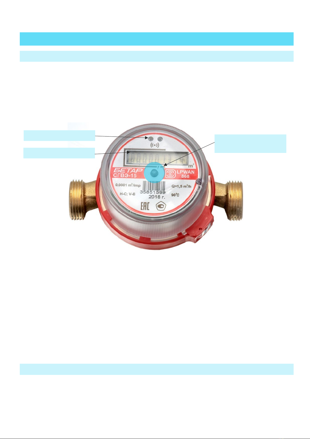
The device has LED indicator on a faceplate for visual displaying of the readings (fig. 2). Readings
are displayed in cubic meters up to the fourth decimal point on a cumulative total.
During the operation of the meter, the number of packets sent over the radio channel is displayed
on the LED indicator every 2 minutes, while the “SP” symbol is displayed in the most significant bit (on the
far left).
Figure 2 — Device basic elements
When the meter is turned on for the first time, the following parameters are displayed one by one
on the LED indicator (each one for the 5 seconds):
name of the built-in software of the meter;
software version number;
software ID (check sum);
method of check sum calculation;
serial number of the meter in the “SХХХХХХХХ” format (for example, “S40488568”);
date of the meter verification in the “Id dd.mm.yy” format (for example, “Id 01.01.20”).
2.2 OPTICAL PORT
There is an optical port (fig. 2) for connection to computer, which also used for testing. The adapter
“Opticalport-USB” connected to the USB-port of computer carries out connection between the optical
port and computer. See detailed description of operation with adapter in a part 3.3.2.
External magnetic field
reception area
Optical port
LED indicator

SHVE, SGVE LPWAN 868 VEGA / User Manual
9
“Vega LoRaWAN Configurator” application allows reading and changing the meters parameters.
See detailed application description in a part 3.
The opto-emitter of the optical port is used as a technological optical pulse output for checking
the meter during production. During operation, the meter is verified by the comparison method.
2.3 FSK RADIO CHANNEL
For a local wireless connection to a personal computer, the meter implements switching between
LoRa and FSK modulation modes, that is, an FSK radio channel is implemented.
To organize such a connection, an additional device "Vega FSK Dongle" is used, which is connected
to the USB port of the computer. For a detailed description of how to work with this device, see part 3.3.3.
To read and change the meter parameters, the Vega LoRaWAN Configurator program is used. See
detailed application description in a part 3.
2.4 METER’S OPERATION MODES
To optimize energy consumption, the meter has two operation modes:
"Storage" - the metrological part works (the meter measures the volume and displays the
accumulated water consumption in cubic meters), the communication part does not work (the
meter does not transmit data via the radio channel). In the "Storage" mode, the LED indicator
displays readings in the "СХХХХ.ХХХХ" format (for example, "С0008.7802");
"Operation" - the metrological and communication parts work.
The meter is supplied by default in the "Storage" mode, to remove from which it is necessary to
bring the external magnet for 15-20 seconds to the area of reception of the external magnetic field, see
p. 2.6.
2.5 INTERNAL CLOCK
Time on internal clock may set automatically when the device connects to the “Vega LoRaWAN
Configurator” application and may corrected via LoRaWAN®network.
“IoT Vega TimeCorrector” application carries out an autocorrecting procedure via LoRaWAN®
network. The device sends time correction request once a week.
2.6 ELECTRONIC MAGNETIC SEAL
The meter has a Hall sensor for fixing of the external magnetic field and it is located under faceplate
of the device (fig.2). That function named as an electronic magnetic seal.
From the 1st second of external magnetic field influence, which strong enough, the meter LED
indicator displays warning symbol “b” at the high order digit place (first index) but readings still displaying.
If the external magnetic field influence continues more than 5 minutes, then device actions are
depending on settings (see part 3.6.2):
SHVE, SGVE LPWAN 868 VEGA / User Manual
10
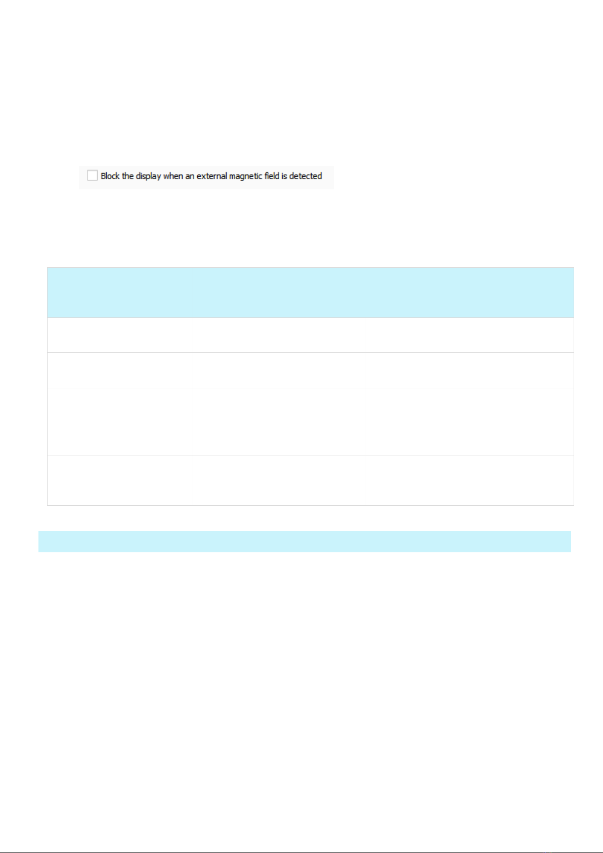
Function “Lock the display in case of detection an external magnetic field” is inactive (by default) –
meter sends emergency message;
Function “Lock the display in case of detection an external magnetic field” is active – device locks
LED indicator and send emergency message with lock flag. Herewith, the LED indicator displays
warning symbol “b” but readings not displaying. Only the dispatcher via the LoRaWAN®network
can unblock a LED indicator using a special command.
There are device controlling functions, which activated by a magnet getting on external magnetic
field reception area in table 2.
Table 2
TIME OF EXTERNAL
MAGNETIC FIELD
INFLUENCE
EVENT
COMMENT
Less than 2 seconds Optical port activation for 20
seconds
After 20 seconds, the optical port is
deactivated if it is not in use
From 3 to 5 seconds Emergency activation of FSK
radio channel
FSK channel becomes active every 2
minutes by default
From 15 to 20 seconds
Emergency communication
session, switching from
“Storage” mode
While communication session the
LED indicator displays warning
symbol “
p” at the high order digit
place but readings still displaying
5 minutes and more Lock of the LED indicator
The LED indicator displays warning
symbol “
b” but readings not
displaying
2.7 CONTROL OF THE PASSIVATION LEVEL OF THE BUILT-IN BATTERY
When the meter is first turned on, the built-in battery is tested to determine the level of passivation.
During testing, the digital indicator displays the inscription "BAT INIT".
Based on the test results, if necessary, the depassivation process is started, in which the digital
indicator displays the inscriptions "BATD xxxx" (at the first stage of the depassivation process) or "BATI xxxx"
(at the second stage), where xxxx is a timer in seconds until the operation is completed.
At the end of the depassivation process, one of the inscriptions will be displayed on the digital
indicator:
"DONE" - in case of successful completion of the depassivation process, after which the meter is
completely ready for operation;
"ERROR" - in case of failure of the depassivation process, after which it is necessary to replace the
built-in battery.

SHVE, SGVE LPWAN 868 VEGA / User Manual
11
During the operation of the meter, the built-in battery is periodically tested to determine the level
of passivation.
2.8 LORAWAN® RADIO CHANNEL
2.8.1 CONNECTION TO THE NETWORK
Meter supports two activation methods in the LoRaWAN®network:
ABP (Activation By Personalization) – meter sends data to the LoRaWAN®network according to
pre-configured schedule (every 12 hours by default).
OTAA (Over The Air Activation) – meter makes three trying to connect the network with
configured frequency plan (RU868 by default). The meter will begin to send data when it receives
the LoRaWAN®activation confirmation. If all attempts fail, the meter will continue to accumulate
data and will attempt to connect to the network every six hours.
By default, meter makes attempts to connect to the network with OTAA method once a day until
it connected to the server. You can change default settings via “Vega LoRaWAN Configurator” application
(see part 3.5).
You can initiate emergency communication session including activation by a magnet getting on
external magnetic field reception area for 15-20 seconds (fig.2).
2.8.2 CLASS А DEVICE
Meter is class A device (by LoRaWAN classification) and has the following features:
ADR («Adaptive Data Rate»);
sending of confirmed messages (configurable);
storing undelivered messages in device memory while sending messages with confirmation;
adjustable data collection and transmission periods;
temperature measurement;
charge measuring of the built-in battery in %.
2.8.3 COMMUNICATION AND COLLECTION PERIODS
2.8.3.1 Communication period
Communication period may be equal to 1, 6, 12 and 24 hours. Device sends data in random point
in time during set period:
If communication period equal to 1 hour, then during the next hour;
If communication period equal to 6 hours, then during the next 6 hours;
If communication period equal to 12 hours, then during the next 12 hours;
If communication period equal to 24 hours, then during the next 24 hours.
2.8.3.2 Data collection period

SHVE, SGVE LPWAN 868 VEGA / User Manual
12
Data collection period may be equal to 1, 6, 12 and 24 hours. Meter saves data in the internal
memory with time by the internal clock:
at 00.00 when the period is equal to 24 hours;
at 00.00 and at 12.00 when the period is equal to 12 hours;
at 00.00, 6.00, 12.00 and 18.00 when the period is equal to 6 hours;
at the beginning of current hour when the period is equal to 1 hour.
The readings are stored in the meter memory until the next communication session; maximum
number of saved messages is 200. At the next communication session, the device starts sending
accumulated messages, from the earliest to the latest.
With the "Confirmed uplinks" option turned off, the device just sends all accumulated messages to
the network in order from the earliest to the latest. There is no check of package delivery in this mode.
Non-transmitted messages do not save in the device memory.
With the "Confirmed uplinks" option turned on, the device will send the next message only after
receiving a confirmation of the delivery of the previous one. If such confirmation has not received after
the fulfilled in the settings uplink number of transmissions, the meter completes the communication
session until the next one according to the schedule. In this case, the device continues to collect data
according to the data collection period and store it in memory. Non-transmitted messages remain in the
device memory until the next communication session.

SHVE, SGVE LPWAN 868 VEGA / User Manual
13
3 “VEGA LORAWAN CONFIGURATOR” APPLICATION
3.1 OPERATING MODES
The "Vega LoRaWAN Configurator" application (hereinafter – application, configurator) is intended
for setting up the device via USB.
The configurator has two modes of operation - "Simple" and "Expert". In the "Simple" mode, only
basic settings are available. In the "Expert" mode, the basic settings, advanced settings, and the ability to
check the coverage area of the signal from the gateways are available. Next, the work of the application is
considered in the “Expert” mode.
Full functionality becomes available after password entering. You can see only
DevEUI and no available any settings or other information without the password.
The “Send Password” command is placed in the “Commands” field in the “Vega
SHVE/SGVE v.2” tab. A password is provided upon request. Instructions for
providing LoRaWAN®keys and passwords for metering devices manufactured by
OOO PKF "BETAR" can be downloaded on the websites iotvega.com and betar.ru in
the relevant sections
3.2 APPLICATION INTERFACE
The "Vega LoRaWAN Configurator" application does not require the special installation. When the
executable file is launched, the window for working with the application appears (fig. 3).
Figure 3 — Application workplace

SHVE, SGVE LPWAN 868 VEGA / User Manual
14
The menu on the left allows you to switch between the “Simple” and “Expert” modes, select the
device model, connect to the device, or disconnect from it, get, and apply settings.
The application window contains three tabs – Device info, LoRaWAN settings and device settings.
The language selection menu is in the upper right corner.
3.3 CONNECTION OF METER TO COMPUTER
3.3.1 ADAPTER CONNECTION, DRIVER INSTALLING
Meter has the optical port for connection to computer, which also used for testing. The adapter
“Optical port-USB” connected to the USB-port of computer carries out connection between the optical
port and computer.
Before connecting the device to the computer for the first time, you must install the driver for the
adapter «MCP2200 Windows Driver», which can be downloaded from iotvega.com. After running the
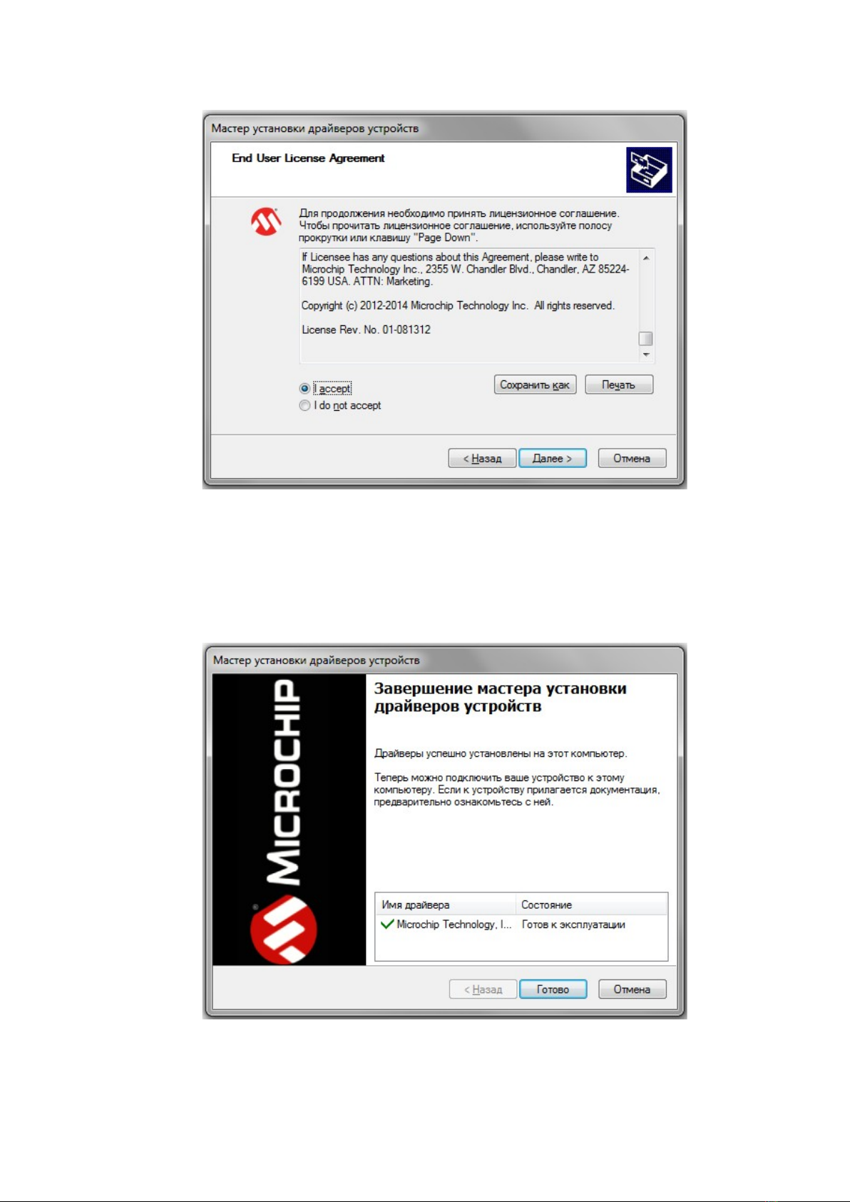
executable file McphCdcDriverInstallationTool.exe, the installer window will appear (fig. 4).
Figure 4 — Window «Мастер установки драйверов устройств»
In this window, you need to click «Далее». In the window that appears, agree to the terms of the
license agreement, then «I accept» and «Далее» (fig. 5). The installation will begin after that.
SHVE, SGVE LPWAN 868 VEGA / User Manual
15
Figure 5 — Driver installing
After finish of install process the window will appears (fig. 6). After pressing «Готово» adapter
“Opticalport-USB” is ready for operation.
Figure 6 — Driver installing successfully

SHVE, SGVE LPWAN 868 VEGA / User Manual
16
3.3.2 OPTICAL PORT ACTIVATION
Launch the program and activate optical port.
For optical port activation the magnet getting on external magnetic field reception area during
short time (less than 2 seconds). Whereupon the optical port activates for the 20 seconds. “Optical port-
USB” adapter must be located and fixed for an operation time as it shown on figures 7,8.
Figure 7 — “Optical port-USB” adapter location in relation to meter_ General view
Figure 8 — “Optical port-USB” adapter location in relation to meter_ Close-up
At the main window of the application, you need to choose the device model (“Vega SHVE/SGVE
v.2”), COM-port number and press “Connect” button (fig. 9) while optical port is active.
Figure 9 — The main settings view for connection the device
Application connects to the device and device selection menu becomes inactive.

SHVE, SGVE LPWAN 868 VEGA / User Manual
17
To read the settings from the device, you need to click the "Get settings" button (fig. 10), until this
point the application will display the default settings or from the last connected device.
Figure 10 — “Device info” tab
After making the necessary changes to the settings, you should click the "Apply settings" button
and only then disconnect from the device with the "Disconnect" button.
3.3.3 FSK RADIO CHANNEL CONNECTION
The FSK radio channel allows you to organize a local wireless (up to several tens of meters)
connection to the meter for reading and changing its parameters.
To connect via FSK you will need:
Vega FSK Dongle, which is connected to the USB port of a personal computer;
FSK key, which is individual for each meter and is provided upon request, along with identification
numbers and keys of the LoRaWAN®network.
The connection procedure is as follows:
1. To connect FSK dongle to PC via USB
2. Run «Vega LoRaWAN Configurator» application
3. Click «Connect» bottom in left menu
Application will automatically recognize device type and device model menu will be inactive.
Figure 11 — FSK connection window
SHVE, SGVE LPWAN 868 VEGA / User Manual
18
4. Click «Get settings» bottom and make sure frequency plan matches to frequency plan of
LoRaWAN device you plan connect to via FSK.
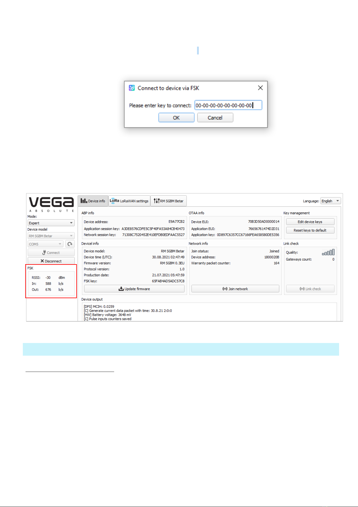
5. Click «Connect to device via FSK».
6. Insert FSK key of the device in appears window and click «ОК».
Figure 12 — Window for entering FSK key
The connection to the device will occur as if it were connected via USB, but a window with FSK
communication parameters will appear in the menu on the left. All settings are performed as with USB
connection, using the buttons «Get settings» и «Save settings».
Figure 13 — “Device info” tab
3.4 “DEVICE INFO” TAB
3.4.1 BASIC DESCRIPTION
The "Device info" tab displays network information about the device, - there are basic information
(Device info field), current state (Network info, Link check), keys for device activation in LoRaWAN network
(ABP info, OTAA info, Key management), log (Device output).

SHVE, SGVE LPWAN 868 VEGA / User Manual
19
Figure 14 — “Device info” tab
3.4.2 FIELDS DESCRIPTION
3.4.2.1 «ABP info» – displays the data necessary to register the device in the LoRaWAN®network
with ABP method (Activation By Personalization).
3.4.2.2 «OTAA info» – displays the data necessary to register the device in the LoRaWAN®network
with OTAA method (Over The Air Activation).
3.4.2.3 «Key management» (not displayed in the "Simple" mode) – allows you to change the factory
device activation keys or reset the keys back to the factory settings (fig. 15).
Figure 15 — “Edit device keys” window at “Key management” field
3.4.2.4 «Device info» – displays information about the device model, its firmware version and time
in UTC (+0.00), factory number and meter verification date.

SHVE, SGVE LPWAN 868 VEGA / User Manual
20
The date of the meter verification does not correspond to the current
3.4.2.5 «Network info» – shows whether the device connecting to the LoRaWAN network and its
network address.
3.4.2.6 «Join network» button – launch the LoRaWAN network connection procedure with the
previously selected ABP or OTAA method. If the device is already connecting to the network, reconnection
procedure will occur.
3.4.2.7 «Link check» button (not displayed in the "Simple" mode) – when pressed, the device sends
a special signal to the LoRaWAN network, in response to which the network informs it about the number
of gateways that received this signal and the signal quality (fig. 16). This button only works while the device
is connecting to the network.
Figure 16 — “Link check” field
3.4.2.8 «Device output» (not displayed in the "Simple" mode) – monitoring the device status,
displaying all events in real time.
3.5 “LORAWAN SETTINGS” TAB
3.5.1 BASIC DESCRIPTION
The "LoRaWAN Settings" tab allows you to configure various parameters of the LoRa network (fig.
17).
Figure 17 — “LoRaWAN settings” tab
This manual suits for next models
1
Table of contents


