Beyerdynamic UNITE CC Series User manual

UNITE CC
COCKPIT CASE
QUICK START GUIDE
KURZANLEITUNG


engl sh
Unite CC – Cockpit Case
3
The Unite CC cockpit case belongs to the wireless Unite system from beyer ynamic. For etaile escriptions of the
use, please refer to the operating instructions for the entire system, which you can ownloa from the internet at:
www.beyer ynamic.com/unite
1. Safety nstruct ons
General
• READ the operating instructions.
• KEEP the operating instructions.
• HEED all warnings.
• FOLLOW all instructions.
D scla mer
• beyer ynamic GmbH & Co. KG will not be liable if any amage, injury or acci ent occurs ue to negligent, incorrect
or inappropriate operation of the pro uct.
1. Rea these inructions.
2. Keep these inructions.
3. Hee all warnings.
4. Follow all inructions.
5. Do not use this evice near water.
The lightning flash within an equilateral triangle is inten e to alert the user to the presence of uninsulate
angerous voltage within the evice that may be sufficient enough to constitute a risk of electric shock to
users.
The exclamation mark within an equilateral triangle is inten e to ale the user to the presence of impoant
operating an maintenance inructions in the literature accompanying the pro uct.

6. Clean only with ry cloth.
7. Do not block any ventilation openings. Inall in accor ance with the manufacturer’s inructions.
8. Do not inall near any heat sources such as ra iators, heat regiers, oves, or other evice (inclu ing amplifiers)
that pro uce heat.
9. For safety purposes o not make any changes to the polarize or groun ing type plug. A polarize plug has two
contacts with one wi er than the other. A groun ing type plug has two contacts an a thir groun ing prong. The
wi e contact or the thir prong are provi e for your safety. If the provi e plug oes not fit into your outlet,
consult an electrician for replacement of the obsolete outlet.
10. Protect the power cor by not walking or an ing on it or pinching, this is consi ere for plugs especially where
they exit from the evice.
11. Only use attachments/accessories specifie by the manufacturer.
12. Use only with the ca, an , tripo , bracket, or table specifie by the manufacturer, or sol with the evice. When
a ca is use , use caution when moving the ca/ evice combination to avoi injury from tipping over.
13. Unplug this evice uring lightning orms or when unuse for long perio s of time.
14. Refer all servicing to qualifie service personnel. Servicing is require when the evice has been amage in any
way, such as power supply cor or plug is amage , liqui has been spille or objects have fallen into the evice,
the evice has been expose to rain or moiure, oes not operate normally, or has been roppe .
Locat on
• The equipment must be set up so that the mains switch, mains plug an all connections on the rear of the evice are
easily accessible.
• If you transport the equipment to another location take care to ensure that it is a equately secure an can never
be amage by being roppe or by impacts on the equipment.
F re hazard
• Never place nake flames (e.g. can les) near the equipment.
Unite CC – Cockpit Case
4

engl sh
Unite CC – Cockpit Case
5
Hum d ty / heat sources
• Never expose the equipment to rain or a high level of humi ity. For this reason o not install it in the imme iate
vicinity of swimming pools, showers, amp basement rooms or other areas with unusually high atmospheric humi ity.
• Never place objects containing liqui (e.g. vases or rinking glasses) on the equipment. Liqui s in the equipment
coul cause a short circuit.
• Do not install near any heat sources such as ra iators, heat registers, stoves or other evice (inclu ing amplifiers)
that pro uce heat.
Connect on
• The equipment must be connecte to a mains socket that has an earth contact.
• Protect the power cor by not walking or an ing on it or pinching, this is consi ere for plugs especially where they
exit from the evice.
• Lay all connection cables so that they o not present a trip hazar .
• Whenever working on the equipment switch off all inputs an outputs to the power supply.
• Check whether the connection figures comply with the existing mains supply. Serious amage coul occur ue to
connecting the system to the wrong power supply. An incorrect mains voltage coul amage the equipment or
cause an electric shock.
• Please note that ifferent operating voltages require the use of ifferent types of power cable an plugs.
Please refer to the following table:
• If the equipment causes a blown fuse or a short circuit, isconnect it from the mains an have it checke an repaire .
• Do not hol the mains cable with wet han s. There must be no water or ust on the contact pins. In both cases you
coul receive an electric shock.
Voltage Power plug accord ng to andard
110 - 125 V UL817 an CSA C 22.2 no. 42.
220 - 230 V CEE 7 page VII, SR section 107-2-D1/IEC 83 page C4.
240 V BS 1363 (1984): “Specification for 13A fuse plugs an switche an un-switche socket outlets.”

Unite CC – Cockpit Case
6
• The mains cable must be firmly connecte . If it is loose there is a fire hazar .
• Always pull out the mains cable from the mains an /or from the equipment by the plug – never by the cable. The
cable coul be amage an cause an electric shock or fire.
• Do not use the equipment if the mains plug is amage .
• If you connect efective or unsuitable accessories, the equipment coul be amage . Only use connection cables
available from or recommen e by beyer ynamic.
Sw tch ng off
• When switching off the evice, also isconnect the power plug from the power socket. Make sure that you o not
pull on the cable, but on the power plug.
Vent lat on
• Do not insert objects into the ventilation grilles or other openings. You coul amage the equipment an /or injure
yourself.
D sconnect
• For pluggable equipment, the socket-outlet shall be near the equipment an shall be easily accessible.
Ma ntenance
• Only clean the equipment with a slightly amp or ry cloth. Never use solvents as these amage the surface.
Trouble shoot ng and serv c ng
• Never open the evice yourself. You coul receive an electric shock. There are no user-serviceable parts insi e.
• Leave all service work to authorise expert personnel.

engl sh
Unite CC – Cockpit Case
7
D sposal
This symbol on the pro uct, in the instructions or on the packaging means that your electrical
an electronic equipment shoul be ispose at the en of its life separately from your house-
hol waste. There are separate collection systems for recycling in the EU. For more information,
please contact the local authority or your retailer where you purchase the pro uct.
Battery d sposal
This symbol means that accor ing to local laws an regulations your pro uct an /or its battery
shall be ispose of separately from househol waste. When this pro uct reaches its en of life,
take it to a collection point esignate by local authorities. The separate collection an recycling
of your pro uct an /or its battery at the time of isposal will help conserve natural resources an
ensure that it is recycle in a manner that protects human health an the environment.
• Ol batteries may contain substances that are harmful to your health an environment.
• Dispose use batteries always accor ing to the applicable isposal regulations. Please o not
throw use battery packs into the fire ( anger of explosion) or your househol rubbish, take
them to your local collection points. The return is free an require by law. Please ispose
ischarge batteries only.
• All batteries are recycle to reclaim valuable material such as iron, zinc or nickel.
Charg ng
• A completely new battery may nee to be charge an ischarge several times before it has reache its full
change capacity.
• Do not throw use batteries in the househol wae, but han them over to the local collection points.
• High ambient temperatures uring charging (> +40 °C) aect the eiciency of the charging process an the lifetime
of the rechargeable battery.

Unite CC – Cockpit Case
8
2. Vers ons
Unite CC-24P Case for charging, transport an storage,
with max. 24 charging compartments for bo ypack receivers / transmitters,
network connection, integrate power supply . . . . . . . . . . . . . . . . . . . . . . . . . . . . . . . Or er # 713.074
Unite CC-36P same as above, but with max. 36 charging compartments
for bo ypack receivers / transmitters . . . . . . . . . . . . . . . . . . . . . . . . . . . . . . . . . . . . . . . . Or er # 728.306
3. Suppl ed accessor es
Power cable
Key
Quick Start Gui e
4. Opt onal accessor es
Unite CC Bag Storage bag for optional accessories (e.g. hea phones) . . . . . . . . . . . . . . . . . . . . . Or er # 713.066

engl sh
Unite CC – Cockpit Case
9
5. Controls and nd cators
Top v ew of Un te CC-24P vers on
Button for initiating the
pairing process or
clearing store pairing in-
formation in the charger
Status in icator light for
pairing status
Switch for “Pair & Charge”
or “Charge only”
Charging units with
4 charging compartments
each
Slots for more optional
charging units or one
optional charging unit
an one optional
compartment for storing
the Unite TH han hel
transmitter
Pair/Reset
Status
• Pair & Charge
• Charge only
Unite CC – Cockpit Case
10
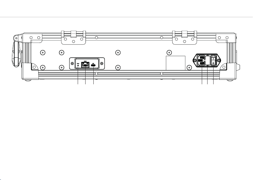
Rear v ew
Reset button
Ethernet connection
USB connection
Mains connection
Fuse rawer (2 x 3.15 A fuse, time-lag)
On-off switch

engl sh
Unite CC – Cockpit Case
11
6. How to operate the Cockp t case
The Unite CC cockpit case is use for charging the rechargeable batteries insi e the bo ypack transmitters an
receivers as well as transmitting the pairing information from the transmitter to the receivers. The Unite CC-24P has
6 charging units, each with 4 charging compartments so that a maximum of 24 bo ypack transmitters or receivers can
be charge simultaneously. The Unite CC-36P has 9 charging units each with 4 charging compartments so that a
maximum of 36 charging compartments are available.
Warn ng: When the Cockpit case is in use, o not mount the cover on the case. There is a risk of overheating an fire.
6.1 Ma ns connect on
• Connect the IEC connector of the power cable to the mains connection of the Cockpit case. Connect the power plug
to a power outlet.
• Switch on the Cockpit case via the on-o switch.
• When not in use, switch o the evice an isconnect the power plug from the power socket. Make sure that you o
not pull on the cable, but on the power plug.
6.2 Establ sh pa r ng
Transmitters an receivers must be paire so that they can communicate with each other. For a successful
pairing the channel name, group ID an au io encryption key are require . The require au io encryption
key is generate in the Unite CC cockpit case or via the Unite Manager software an uring the pairing
process it is first store on the cockpit case an then it is transferre to the transmitter an receiver in the
charging compartments. In this context, please also note the position of the switch on the cockpit case. The
switch must be set to the “Pair & Charge” position so that the pairing information can be transmitte from
the Unite CC to the transmitters an receivers.
There are three ifferent ways to pair the Unite transmitters with receivers:
1. Via an in ivi ual charger (refer to the following escription or system manual online).
2. Using the Unite Manager Software on a PC (refer to the Unite Manager Software manual or system
manual online).
3. Via ynamic channel search (refer to system manual online, chapter “Special functions”.

Unite CC – Cockpit Case
12
Use w th group ID 256
By efault, the transmitters an receivers are supplie with the group ID 256.
A factory-set au io encryption key, which cannot be change , is use for the factory-set group ID 256. The
au io encryption key ensures a itional security against unauthorise listening. You can use the group ID
256 for a system w thout pairing.
Receivers with the group ID 256 can fin an connect to all transmitters with the group ID 256. This is one
via the ynamic channel search on the receiver.
Attent on: When using several transmitters (e.g. Unite AP4 an several Unite TP) with the group ID 256 at the
same time, make sure that the in ivi ual channel names iffer from each other! Otherwise this can cause
connection problems with the receivers!
Use w th nd v dual group ID
If several receivers are to be ivi e into ifferent groups, for each group an in ivi ual group ID can be
assigne . A separate au io encryption key is generate for an in ivi ual group ID in or er to ensure
a itional security against unauthorise listening. This au io encryption key is generate uring the
pairing process, store in the charger an transmitte from the charger to the transmitter an receiver,
along with the channel name an group ID.
Since the au io encryption key is not transmitte via ra io, it cannot be rea out. This gives the system
maximum security against unauthorise listening.
The receivers can only connect to a transmitter with which they have been paire . If the group ID is
subsequently set manually on the receiver, no connection can be establishe because the au io
encryption key oes not match. Please note that the transmitter to which the receivers are to be
connecte must be efine as the master.

engl sh
Unite CC – Cockpit Case
13
In or er to perform a pairing with an in ivi ual charger, procee as escribe in the following:
1. Set the esire group ID on the transmitter you want to use for pairing. Refer also to chapter 5.2 of the “Unite TP –
Bo ypack Transmitter”.
2. Insert only one transm tter into the charging compartment of the charger. If multiple transmitters are inserte into
the charging compartments, the pairing will not start an the status in icator on the charger will isplay an
error (see table). Alternatively, you can connect the transmitter to the USB port, type C on the charger via a USB
cable.
3. Insert one or more receivers into the charging compartments of the charger to be paire with the transmitter. You
can also connect another receiver to the charger using the USB port. Remove all receivers that shoul not be
paire . If there is no receiver in the charging compartments, the pairing information is store in the charger. This is
use for later pairing without connecting the transmitter to the charger.
4. In or er to transfer the pairing information from the transmitter to the receivers in the slots an to the charger itself
for future pairing, press an hol the “Pair/Reset” button on the charger for more than 2 secon s. The status
in icator will flash yellow for several secon s if the pairing is successful. The status in icator will then remain
yellow because the pairing information is now also store in the charger.
5. If you want to pair other receivers, remove the transmitter an all receivers from the charger, set the switch
to “Pair & Charge” an insert the unpaire receivers into the charger. The pairing information will be store
imme iately in the unpaire receivers. The status in icator on the receiver will flash yellow rapi ly while this
happens.
6. Set the switch back to “Charge only” when the pairing is finishe , so that the charger can only be use for
recharging.
7. Switch on the transmitter an one receiver to check that they have both been paire successfully.
After a few secon s, the status in icator on the receiver shoul light up green an the isplay shoul show the
channel name of the transmitter.
8. If you want to clear the store pairing information, hol own the “Pair/Reset” button for more than five secon s.
The status in icator will then remain permanently green.

Unite CC – Charging Case
14
Ind cator l ght Operat ng status
Off Device is switche off
Green • Device is rea y to use
• No pairing information save
Flashing yellow Pairing information is being copie to the charger or receiver
Yellow Pairing information has been store in the charger
Flashing green/yellow Device is being localise
Flashes re 5 times • No transmitter
• Too many transmitters
Flashing re rapi ly • Operating error
• Charging error
When in the pairing mo e (switch set to “Pair & Charge”) the status in icator on the charger shows the
following information:

engl sh
Unite CC – Charging Case
15
6.3 Charg ng
1. Set the switch to “Charge only”.
2. Insert the bo ypack receivers / transmitters into the charging compartments so that the charging contact of the
transmitters / receivers have contact with those in the charging unit.
3. Charging will start automatically.
4. The state of charge of the batteries is in icate by the LED of the appropriate evice:
Ind cator l ght Charg ng status
Off Device is switche off
Flashing green slowly Charging 0 - 100%
Green Battery is charge
Flashing yellow slowly Pairing information is being copie from the transmitter
Yellow for 10 secon s Device information is copie successfully to charger/ evices
Flashes re slowly for 10 secon s • Too many transmitters in the charger when pairing is initiate
• Other pairing error
Flashing green/yellow rapi ly Device is being localise
Flashing re rapi ly Charging error

Unite CC – Cockpit Case
16
6.4 Automat c F rmware Update
• By using the Unite Cockpit Case you can uploa firmware up ates to Unite transmitters/receivers.
• With the current factory setting the Unite Cockpit Case will automatically up ate the firmware of the Unite
transmitters/receivers uring the f rst charging process. Just insert the transmitters/receivers into the charging
compartments.
During the firmware up ate the status in icator light of the Unite transmitters/receivers will illuminate re . This
process will take approx. 5 minutes. Shoul the process take longer than 10 minutes, turn the Unite Cockpit Case off
an on again. The up ate process will then restart.
Attent on:
Please note that after a successful up ate to a new firmware version, the Unite transmitters/receivers are no longer
compatible with ol er firmware versions.
6.5 Cond t on ng the battery
• In or er to achieve the maximum capacity of the battery, we recommen ischarging the transmitters/receivers
completely to carry out a complete charging cycle afterwar s.
• This also increases the accuracy of the battery in icator on the isplay of the Unite transmitters/receivers.
6.6 Serv ce mode
• For maximum operational reliability, the Unite Cockpit Case features a so-calle service mo e.
• If the evice is isconnecte from the mains within 45 secon s after being switche on (e.g. by acci ental
switching off), the evice will boot in a safety mo e an check itself.
• If this service mo e is activate automatically (after booting unsuccessfully), the system will return to its usual
operating mo e after approx. 3 minutes.

engl sh
Unite CC – Cockpit Case
17
7. Techn cal spec f cat ons
AC input . . . . . . . . . . . . . . . . . . . . . . . . . . . . . . . . . . . . . 100 - 240 V AC, 50-60 Hz
Fuse . . . . . . . . . . . . . . . . . . . . . . . . . . . . . . . . . . . . . . . . . 2 x 3.15 A (time-lag)
Nominal current . . . . . . . . . . . . . . . . . . . . . . . . . . . . . 2.2 A @115 V AC, 1.1 A @230 V
Power consumption . . . . . . . . . . . . . . . . . . . . . . . . . 150 W with 24 charging compartments
225 W with 36 charging compartments
Max. charging time . . . . . . . . . . . . . . . . . . . . . . . . . . 4 hours
Connections. . . . . . . . . . . . . . . . . . . . . . . . . . . . . . . . . Ethernet
USB type C
Temperature range
Operation. . . . . . . . . . . . . . . . . . . . . . . . . . . . . . . . . . 0 to +28 °C
Storage . . . . . . . . . . . . . . . . . . . . . . . . . . . . . . . . . . . . -20 to +50 °C
Relative humi ity . . . . . . . . . . . . . . . . . . . . . . . . . . . . 0 to 90%
Dimensions incl. han le, base (L x W x H). . . . . 530 x 445 x 180 mm
[20.7" x 17.5" x 7.1"]
Weight
Unite CC-24P. . . . . . . . . . . . . . . . . . . . . . . . . . . . . . . 12.6 kg [27.78 lbs]
Unite CC-36P. . . . . . . . . . . . . . . . . . . . . . . . . . . . . . . 13.0 kg [28.66 lbs]
Charging compartments
Unite CC-24P. . . . . . . . . . . . . . . . . . . . . . . . . . . . . . . max. 24 for bo ypack transmitters / bo ypack receivers
Unite CC-36P. . . . . . . . . . . . . . . . . . . . . . . . . . . . . . . max. 36 for bo ypack transmitters / bo ypack receivers

Unite CC – Cockpit Case
18
Unite
Operating instructions
Unite
Lan ing page
8. QR Codes

engl sh
Unite CC – Cockpit Case
19

Unite CC – Cockpit-La egerät
20
Das Cockpit-La egerät Unite CC ist für as Drahtlos-System Unite von beyer ynamic vorgesehen. Detaillierte Beschrei-
bungen zum Gebrauch entnehmen Sie bitte er Be ienungsanleitung es Gesamtsystems, welche Sie im Internet unter
www.beyer ynamic.com/unite herunterla en können.
1. S cherhe ts nformat onen
Allgeme n
• LESEN Sie ie Be ienungsanleitung
• BEWAHREN Sie iese Be ienungsanleitung auf.
• BEFOLGEN Sie ie aufgeführten Be ienungs- un Sicherheitshinweise.
Haftungsausschluss
• Die Firma beyer ynamic GmbH & Co. KG übernimmt keine Haftung für Schä en am Pro ukt o er Verletzungen
von Personen aufgrun unachtsamer, unsachgemäßer, falscher o er nicht em vom Hersteller angegebenen Zweck
entsprechen er Verwen ung es Pro ukts.
1. Bitte lesen Sie iese Anweisungen.
2. Bitte bewahren Sie iese Anweisungen auf.
3. Bitte beachten Sie alle Warnhinweise.
4. Folgen Sie allen Anweisungen.
5. Verwen en Sie ieses Gerät nicht in er Nähe von Wasser.
6. Reinigen Sie as Gerät nur mit einem trockenen Tuch.
Das Blitzsymbol in einem gleichschenkligen Dreieck wei en Anwen er auf eine nicht isoliee un potenziell
gefährliche Berührungsspannung innerhalb es Gerätes hin, ie ark genug sein kann, um bei Anwen ern
einen Stromschlag auszulösen.
Ein Ausrufezeichen in einem gleichschenkligen Dreieck wei en Anwen er auf wichtige Anweisungen zum
Betrieb un Inan haltung es Pro uktes in en begleiten en Unterlagen hin.
This manual suits for next models
2
Table of contents
Languages:
Other Beyerdynamic Batteries Charger manuals

Beyerdynamic
Beyerdynamic UNITE CDD-8/4 User manual

Beyerdynamic
Beyerdynamic SLG 300 H User manual

Beyerdynamic
Beyerdynamic LG 30 User manual

Beyerdynamic
Beyerdynamic Synexis SG 24 Configuration guide

Beyerdynamic
Beyerdynamic Synexis C30 User manual

Beyerdynamic
Beyerdynamic WA-CDb User manual

Beyerdynamic
Beyerdynamic SLG 900 User manual

Beyerdynamic
Beyerdynamic Unite CC-24P User manual


