Confermiamo che questo prodotto è conforme
alle seguenti Direttive Europee: 89/336/CEE -
73/23/CEE e modifiche successive.
1) GENERALITA'
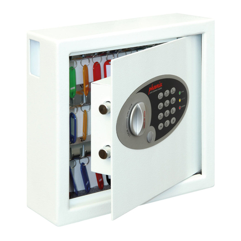
La cassetta di sicurezza Mod. SIBOX è un con-
tenitore antiefrazione da incassare a parete. La
serratura di sicurezza è del tipo a cilindri radiali.
É particolarmente indicata per contenere sistemi
di sblocco e di comando delle serrande.
2) DIMENSIONI (fig.1)
3) MONTAGGIO
Eseguire lo scavo nel muro sufficiente a ricevere
la cassetta e prevedere le canalette per i collega-
menti.
Fissare le zanche di aggrappaggio (fig.2 rif.A) sul
retro della cassetta. Cementare la cassetta a filo
muro come in fig.2 mantenendo pulito il piano
della cassetta ed i fori di fissaggio della flangia.
Quando il cemento è rappreso, fissare la cornice
(fig.3 rif.A) con le viti (fig.3 rif.V) in dotazione.
4) ACCESSORI
MOX
Sblocco di emergenza con comando a filo(fig.4).
Montaggio
1) Passare il filo d'acciaio "D" che comanda lo
sblocco, nel foro "I" della base "B". Fissare la
base "B" nel fondo della cassetta SIBOX con le
3 viti "H".
2) Posizionare il cuneo bloccafilo "C" nella mano-
pola "A" ed avvitare la vite "E".
3) Posizionare la manopola "A" in posizione di
blocco (completamente inserita).
4) Tirare il filo "D" per portare la guina in appoggio
nella sede per eliminare eventuali laschi.
5)
Bloccare il filo "D" avvitando la vite "E" e bloccare
il filo ecedente con la vite"F" e rondella "G".
N.B. Si consiglia di ingrassare le parti in movi-
mento e il filo d'acciaio.
Lo SBLOCCOper l'apertura manuale si attiva
ruotando completamente la manopola "A" in sen-
so orario (SBLOCCO).
Il BLOCCOper l'apertura motorizzata si ripristi-
na riportando la manopola "A" in posizione inizia-
le ruotando la manopola "A" in senso antiorario
(BLOCCO).
POX-UP
Pulsantiera comando UOMO PRESENTE
(comando diretto del motore).
Montaggio
Eseguire il collegamento di fig.5 e fissare la
placchetta nell'apposito vano (fig.7).
POX-SC
Pulsantiera comando perSCHEDA ELET-
TRONICA DI COMANDO.
Montaggio
Eseguire il collegamento di fig.6 e fissare la
placchetta nell'apposito vano (fig.7).
N.B. Il collegamento deve essere eseguito con
terminali isolati e come indicato nei rispettivi
schemi elettrici.
É obbligatorio il collegamento di massa.
We declare that this product is in conformity with
the following European Directives: 89/336/EEC
and 73/23/EEC and subsequent amendments.
1) GENERAL DESCRIPTION
The Mod. SIBOX safety box is an antibreak-in
container for embedding into walls. The safety
lock is the radial cylinder type.
The box is designed particularly to house release
systems and roll-up door controllers.
2) DIMENSIONS (fig. 1)
3) ASSEMBLY
Make a hole in the wall which is large enough to
house the box and provide raceways for
connections.
Secure the fastening brackets (fig.2 rif.A) to the
back of the box. Cement in the box until it is flush
with the wall as in fig. 2, keeping the box surface
and the flange fastening holes clean. When the
cement has set, fasten the (fig.3 rif.A) frame
using the (fig.3 rif.V) screws supplied.
4) ACCESSORIES
MOX
Emergency release mechanism with wire
control (fig. 4).
Assembly
1) Introduce the steel wire "D" for release
mechanism control into the hole "I" in the base
"B". Fasten the base "B" to the bottom of the
SIBOX box using the 3 screws "H".
2) Position the wire blocking wedge "C" in the
knob "A" and tighten the screw "E".
3) Position the knob "A" in locking position
(completely inserted).
4) Pull the wire "D" to bring the sleeve to rest in
position in order to eliminate any slack.
5) Secure the wire "D" by tightening the screw "E"
and secure the surplus wire with the screw "F"
and the washer "G".
N.B. The moving parts and the steel wire should
be greased.
TheRELEASE MECHANISMfor manual opening
is activated by completely turning the knob "A"
clockwise (RELEASE).
The BLOCKING MECHANISM for motor-driven
opening is reset by turning the knob "A"
anticlockwise (BLOCK) to bring the knob "A"
back to the original position.
POX-UP
HOLD-TO-RUN control push-button board
(direct motor control).
Assembly
Carry out the connection shown in fig. 5 and
fasten the plate in the correct position (fig. 7).
POX-SC
Push-button board for ELECTRONIC
CONTROL BOARD.
Carry out the connection shown in fig. 6 and
fasten the plate in the correct position (fig. 7).
N.B. The connection should be carried out with
insulated terminals and following the relevant
wiring diagrams.
The earth connection must be made.
ITALIANO ENGLISH
