Biamp Tesira TCM-1 User manual

TCM-1 Beamtracking™ Ceiling Microphone
TCM-1A Beamtracking™ Ceiling Microphone with Amplifier
TCM-1EX Beamtracking™ Expansion Ceiling Microphone
OPERATION MANUAL
SEPTEMBER 2018

TCM-1, TCM-1A & TCM-1EX PRODUCT DESCRIPTION
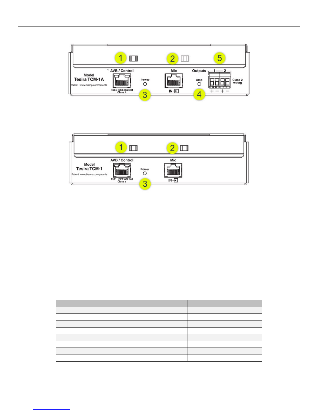
Tesira TCM-1
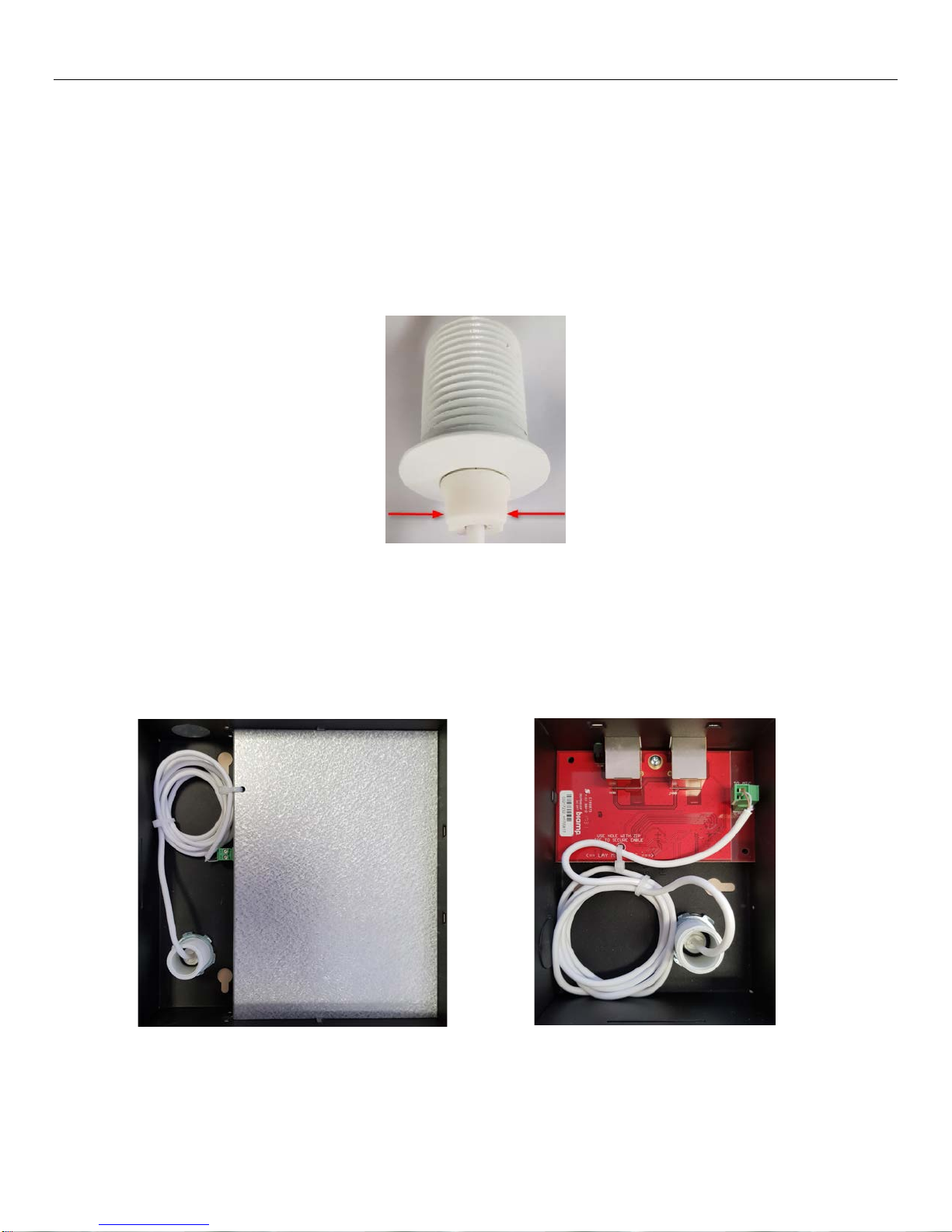
The TCM-1 is an AVB ceiling microphone for use in Tesira systems. Comprising a pendant microphone and plenum box,
each microphone includes Beamtracking™ technology with three 120-degree zones, providing full 360-degree coverage
of the meeting space. The TCM-1 microphone actively tracks and intelligently mixes conversations from around the table,
allowing far-end conference participants to experience the conversation naturally. The Tesira TCM-1 comes with its own
digital signal processing module for Beamtracking, and each plenum box comes with an additional RJ-45 connector for
daisy-chain connections. A maximum of three microphones are permitted per daisy chain (one TCM-1 required, plus up to
two TCM-1EX).
Tesira TCM-1A
The TCM-1A is an AVB ceiling microphone and PoE+ amplifier for use in Tesira systems. Comprising a pendant
microphone and plenum box, each microphone includes Beamtracking™ technology with three 120-degree zones,
providing full 360-degree coverage of the meeting space. The TCM-1A microphone actively tracks and intelligently mixes
conversations from around the table, allowing far-end conference participants to experience the conversation naturally.
The 2-channel PoE+ amplifier includes an internal limiter, software configurable amplification, and a “burst” mode to
support higher power levels for dynamic content. The TCM-1A comes with its own digital signal processing module for
Beamtracking, and each plenum box comes with an additional RJ-45 connector for daisy-chain connections. A maximum
of three microphones are permitted per daisy chain (one TCM-1A required, plus up to two TCM-1EX).
Tesira TCM-1EX
The TCM-1EX is an expansion ceiling microphone for use with the TCM-1 or TCM-1A in Tesira systems. Comprising a
pendant microphone and plenum box, each microphone includes Beamtracking™ technology with three 120-degree
zones, providing full 360-degree coverage of the meeting space. The TCM-1EX provides an expansion microphone for a
TCM-1 & TCM-1A which actively tracks and intelligently mixes conversations from around the table, allowing far-end
conference participants to experience the conversation naturally. The Tesira TCM-1EX is intended to be used as a
second or third microphone in conjunction with a TCM-1 or TCM-1A; it cannot operate as a standalone device. Each
plenum box comes with an additional RJ-45 connector for daisy-chain connections. A maximum of three microphones are
permitted per daisy chain (one TCM-1 or TCM-1A required, plus up to two TCM-1EX).

TCM-1, TCM-1A & TCM-1EX SETUP AND USE
Tesira TCM-1 Tesira TCM-1A
Tesira TCM-1EX
Tesira AVB Beamtracking pendant microphone
for use with TCM-1, TCM-1A and TCM-1EX
Setup and Use
The Tesira software provides an intuitive interface for setup and programming of the TCM-1, TCM-1A and the TCM-1EX.
The information supplied by this manual relates to physical connections and device setup. For more details on software
setup, please consult the Tesira Help File. For device specifications and microphone polar pattern please consult the
datasheet. Note that the pendant microphone is available in black or white. Functionality is identical.
The Tesira TCM-1, TCM-1A and TCM-1EX do not connect with Telecom Network Voltage (TNV) circuitry and are
considered Network Environment Zero devices

TCM-1 & TCM-1A FRONT PANEL
Figure 1 TCM-1A
Figure 2 TCM-1
1. AVB/Control
Facilitates connection to the Tesira AVB network for audio transmission and control. This RJ-45 port may either
be connected directly to the Tesira AVB port (via a PoE+ injector) for a single device system, or via a PoE+
network switch in a multi-device AVB system. The TCM-1 is an IEEE 802.3 Type 1 Class 3 PoE device requiring
15.4W of PoE power. The TCM-1A is an IEEE 802.3 Type 2 Class 4 device requiring 30W of PoE+ power. There
are no other provisions for power inlet.
2. Mic (IN)
Allows up to two additional TCM-1EX expander microphone units in a daisy-chain topology. Use of this RJ-45 port
is optional and will depend on the number of additional microphones required to cover the acoustic space.
3. Power LED
A multi-color LED provides information about the status of the device.
Status
LED Indicator
No power
Off
Booting / Self-Test
Red Solid
Ready to receive configuration or updating firmware
Yellow Solid
Configured and ready to participate in the system
Green Solid
Unit is in Locate mode (triggered from the software)
Green Flashing
Unit has Major Alarm condition
Red Flashing
Unit has Minor Alarm condition
Yellow Flashing
Unit has both a Major and Minor Alarm condition
Red & Yellow Flashing

TCM-1 & TCM-1A FRONT PANEL
4. Amp LED (TCM-1A only)
A multi-color LED provides information about the status of the amplifier.
Status
LED Indicator
No power
Off
Powered
Green Solid
Amplifier limiter engaged
Yellow Solid
Amplifier is in Locate mode (triggered from the software)
Green Flashing
Amplifier has Major Alarm condition
Red Flashing
PoE+ power is not available or insufficient to power the
amplifier - it has been turned off
Red & Yellow Flashing
5. Output 1 & 2 (TCM-1A only)
2 x 4W RMS or 1 x 8W RMS output at low impedance 4Ω / 8Ω.

TCM-1EX FRONT PANEL
Figure 3 TCM-1EX
1. Mic (IN)
Allows for connection of a single additional TCM-1EX expander microphone unit in a daisy-chain topology, with a
maximum of 2 TCM-1EX units per TCM-1 or TCM-1A. Use of this RJ-45 port is optional and will depend on the
number of additional microphones required to cover the acoustic space.
2. Mic (OUT)
Facilitates connection to the host TCM-1 or TCM-1A unit or can be used to provide a link to the TCM-1EX when
used a multi-microphone daisy-chain topology.
3. Link LED
Illuminates when a valid link is detected from the host TCM-1 or TCM-1A.

TCM-1, TCM-1A & TCM-1EX MICROPHONE
Figure 4TCM-1, TCM-1A and TCM-1EX Microphone
1. LED Indicators
3x multi-color LED’s offset by 120 degrees provide information about the status of the microphone. Default LED
indication is shown in the table below. Some LED behavior may be changed during configuration of the software.
Status
LED Indicator
No power
Off
Configured and operating normally
Green Solid
Unit is in Locate mode (triggered from the software)
Green Flashing
Microphone is Muted
Red Solid
Unit has a Major Alarm condition
Red Flashing
2. Biamp Logo
Defines the front of the microphone when looking at the Azimuth Angle in the software.

TCM-1, TCM-1A & TCM-1EX WIRING TOPOLOGIES
Example Topologies
Figure 5 TCM-1A with 2x TCM-1EX
Figure 6 TCM-1 with 2x TCM-1EX
NOTE: The TCM-1 and TCM-1A cannot be daisy-chained together.

TCM-1, TCM-1A & TCM-1EX WIRING TOPOLOGIES
Example Topologies – Amplifier Speaker Wiring
Figure 7 Amplifier speaker wiring (TCM-1A only)
All speaker wiring connections require Class 2 wiring and should be made by qualified personnel with the amplifier power
removed.
Channel Assignment & Power Ratings
The amplifier can be configured in either single channel or two channel mode in the Tesira software. In 2 channel mode,
outputs 1 & 2 will be active and pass audio. In single channel mode, only channel 1 will be active and pass audio. Channel
2 will not pass audio even if a speaker is connected.

TCM-1, TCM-1A & TCM-1EX INTERNAL CONNECTIONS
Internal Connections
The TCM-1, TCM-1A and TCM-1EX plenum is a folded metal enclosure designed for permanent installation on a ceiling
or other horizontal surface, above a ceiling tile, or on a vertical surface. The devices are passively cooled and do not have
ventilation ports.
A 2-pin connector is located on the inside of the plenum to connect the pendant microphone. The connector is keyed to
prevent incorrect polarity. The microphone is designed to be suspended by the cable. The length of the suspended cable
is adjustable by pinching the soft plastic on the under-side of the microphone mount. This allows the cable to be extended
or shortened to the desired length.
Figure 8 Pinch-points for Microphone Cable Length Adjustment
Strain relief for the microphone cable should be fitted using the included zip-ties by securing it to either the circuit board
(TCM-1EX) or the circuit board protective barrier (TCM-1 & TCM-1A) inside the plenum. Excess cable may be coiled as
shown in the figures below.
CAUTION: Make sure the cable is not strained or the zip-tie overtightened as damage may occur.
Figure 9 TCM-1 & TCM-1A Figure 10 TCM-1EX

TCM-1, TCM-1A & TCM-1EX INTERNAL CONNECTIONS
Punch-out through-holes in the plenum allow the microphone cable to exit either vertically or horizontally through the
microphone mount. Keyed mounting holes allow installation on a vertical or horizontal surface or above a ceiling tile. The
plenum design allows for an optional seismic cable to be connected.
If installing the microphone away from the plenum, the cable will be routed through a punch-out through-hole and a strain-
relief grommet (included) must be installed to prevent damage to the microphone cable.
NOTE: Make sure there’s sufficient cable slack outside the plenum to accommodate potential changes in microphone
height.
Figure 11 Strain-Relief Grommet & Installation

TCM-1, TCM-1A & TCM-1EX INSTALLATION
Mounting & Installation
General Mounting and Installation Notes
•The maximum distance between an Ethernet switch and a TCM-1 or TCM-1A plenum box is 330 feet (100
meters).
•The maximum distance between daisy-chained TCM plenum boxes is 33 feet (10 meters).
•The maximum adjustable length of the microphone pendant cable is 16.4 feet (5 meters).
•The TCM-1, TCM-1A and the TCM-1EX may be mounted above the ceiling tile or attached to the ceiling
or a vertical surface. The devices comply with UL-2043 Plenum rating.
•An optional “Tile Bridge” kit (TB-1) may be ordered to facilitate various mounting configurations and
accommodate local safety and code requirements.
Also included:
•1x microphone mounting large-area washer (pre-drilled for seismic cable installation, if required.)
•1x strain-relief grommet
Installation Option – Above Ceiling Tile Mounting
NOTE: the plenum cover must be removed for this installation option. No tools are required.
1. Cut a .825 inch (21mm) hole through the ceiling tile where the pendant microphone is to be located. The
installer may remove the ceiling tile or cut the hole in place, as desired.
2. Install the microphone mount through the hole in the tile and the plenum.
a. The TCM also includes a large-area washer to accommodate installing the microphone through
the ceiling tile in a location away from the plenum.
3. Secure the microphone mount with the retaining hardware (nut) from inside the plenum, or through the
ceiling tile and washer depending on the installation.
4. Set the microphone height by using the pinch points on the mount to extend or retract the cable as
required.
5. Attach the microphone connector to the socket on the inside of the plenum.
a. If installing the microphone away from the plenum, make sure the strain-relief grommet is
installed as shown in Internal Connections.
6. Attach the microphone cable to either the circuit board (TCM-1EX) or the circuit board protective barrier
(TCM-1 & TCM-1A) with the provided zip-ties if mounting the microphone internally.
7. Coil any excess cable inside the unit and secure with a zip-tie as shown in Internal Connectionsif
mounting the microphone internally.
CAUTION: Ensure the cable is not strained or the zip-tie overtightened as damage may occur.
8. Install the plenum cover.

TCM-1, TCM-1A & TCM-1EX INSTALLATION
Figure 12 Above-Ceiling Tile Installation Option
Figure 13 Alternate Above-Ceiling Tile Installation Option

TCM-1, TCM-1A & TCM-1EX INSTALLATION
Installation Option – Ceiling Mounting
NOTE: the plenum cover must be removed for this installation option. No tools are required.
1. Attach the plenum cover to the ceiling with hardware through the keyed mounting holes.
2. Install the microphone mount through the hole in the plenum.
3. Secure the microphone mount with the retaining hardware (nut) from inside the plenum.
4. Set the microphone height by using the pinch points on the mount to extend or retract the cable as
required.
5. Attach the microphone connector to the socket on the inside of the plenum.
6. Attach the microphone cable to either the circuit board (TCM-1EX) or the circuit board protective
barrier (TCM-1 & TCM-1A) with the provided zip-ties.
7. Coil any excess cable inside the unit and secure with a zip-tie as shown in Internal Connections.
CAUTION: Make sure the cable is not strained or the zip-tie overtightened as damage may occur.
8. Install the plenum on to the ceiling-mounted cover.
Figure 14 Ceiling Installation Option
Installation Option – Vertical Mounting
NOTE: the plenum cover must be removed for this installation option. No tools are required.
1. Attach the plenum to the vertical surface with hardware through the keyed mounting holes.
2. Install the microphone mount through the hole in the plenum.

TCM-1, TCM-1A & TCM-1EX INSTALLATION
3. Secure the microphone mount with the retaining hardware (nut) from inside the plenum.
4. Set the microphone height by using the pinch points on the mount to extend or retract the cable as
required.
5. Attach the microphone connector to the socket on the inside of the plenum.
6. Attach the microphone cable to either the circuit board (TCM-1EX) or the circuit board protective
barrier (TCM-1 & TCM-1A) with the provided zip-ties.
7. Coil any excess cable inside the unit and secure with a zip-tie as shown in Internal Connections.
CAUTION: Make sure the cable is not strained or the zip-tie overtightened as damage may occur.
8. Install the cover on to the vertical-mounted plenum.
Figure 15 Vertical Surface Installation

TCM-1, TCM-1A & TCM-1EX INSTALLATION
Installation Option – Tile Bridge (TB-1)
The TB-1 Tile Bridge (ordered separately) may be utilized in several configurations to mount the TCM and
pendant microphone above ceiling tiles, the most common of which are detailed as follows.
The TB-1 kit includes a tile bridge and two clips that are used to mount any of the TCM model plenum boxes and
the pendant microphone. When using the tile bridge to install a microphone, the microphone mounting washer
included with the TCM may be discarded.
NOTE: For these installations, the strain-relief grommet must be installed on the plenum through-hole where the
microphone cable is to be routed. See Internal Connections.
For all installation options, do the following:
•Remove adjacent ceiling tiles to access the area where the TCM and pendant microphone are to be
mounted.
•Cut a .825 inch (21 mm) hole through the ceiling tile where the pendant microphone is to be located.
NOTE: Make sure the slots in the tile bridge will line up with the mounting location. The tile bridge
may be used as a template to ensure proper location.
Installation Option – TCM “Corner” Install
This option installs the TCM in the corner over a ceiling tile where the tile mounting “T-bars” meet.
1. Install the clips on the notched fittings of the TCM plenum top cover as shown:
Figure 16 Clip Installation
2. Fit the clips over two perpendicular T-bars (in the corner) above the ceiling tile with the TCM oriented
as required.
3. Fit the tile bridge over the ceiling tile where the microphone mounting hole was previously cut. The
ends of the tile bridge fit over the ceiling T-bars to secure it in place.
4. Install the microphone mount through the hole in the ceiling and the tile bridge.

TCM-1, TCM-1A & TCM-1EX INSTALLATION
5. Secure the microphone mount with the retaining hardware (nut) from above the ceiling tile.
6. Set the microphone height by using the pinch points on the mount to extend or retract the cable as
required.
Figure 17 TB-1/TCM Corner Installation
7. Route the microphone cable through the strain-relief grommet and attach the connector to the socket
on the inside of the plenum.
8. Coil-up and secure excessive cable with the zip-ties provided.
CAUTION: Ensure the cable is not strained or the zip-tie overtightened as damage may occur.
Installation Option – TCM TB-1 Install
This option installs the TCM on a corner where the tile bridge and the tile mounting “T-bar” meets.
1. Fit the tile bridge over the ceiling tile where the microphone mounting hole was previously cut. The
ends of the tile bridge fit over the ceiling T-bars to secure it in place.
2. Install the clips on the notched fittings of the TCM plenum top cover. See Figure 16 in the previous
section.
3. Fit the clips over the T-bars and the TB-1 above the ceiling tile with the TCM oriented as required.
4. Install the microphone mount through the hole in the ceiling and the tile bridge.
5. Secure the microphone mount with the retaining hardware (nut) from above the ceiling tile.
6. Set the microphone height by using the pinch points on the mount to extend or retract the cable as
required.
9. Route the microphone cable through the strain-relief grommet and attach the connector to the socket
on the inside of the plenum.
7. Coil-up and secure excessive cable with the zip-ties provided.

TCM-1, TCM-1A & TCM-1EX INSTALLATION
CAUTION: Ensure the cable is not strained or the zip-tie overtightened as damage may occur.
Figure 18 Alternative TB-1/TCM Installation
Other Installation Options
Numerous variations of the previously-detailed installations may be achieved, and it is at the installer’s
discretion to determine which configuration will satisfy design considerations while complying with any safety or
local code regulations.
Seismic Cable (optional)
Seismic cable(s) (not included) are available for the TCM-1, TCM-1A and the TCM-1EX.
1. To install the seismic cable, locate the holes in the plenum as identified by the arrows. Holes to accommodate the
cable are in similar locations for all TCM models.
Figure 19 Seismic Cable Installation Figure 20 End-stop Installation
2. Feed the cable through the hole in the plenum so the end-stop remains inside.

TCM-1, TCM-1A & TCM-1EX INSTALLATION
3. Feed the cable through one end of the locking mechanism.
NOTE: the ends indicated by the blue arrow need to be depressed to allow the cable to pass through. Internal
guides make sure the cable will be routed through the correct path.
4. Attach the loop to a secure location and apply sufficient tension for minimal slack.
5. Make sure the ends of the lock mechanism are in the locked position (out) as indicated by the blue arrows.
Figure 21 Lock Mechanism Orientation
NOTE: The tile bridge and large-area microphone mount washer are pre-drilled to accommodate seismic cable
installation to comply with local code and/or safety requirements, as required. It is up to the installer to understand
and determine these requirements.
Visit www.biamp.com to obtain firmware and software updates related to this product. To speak with an Applications Engineer, please call

FCC Notice
FCC Part 15 –
This device complies with part 15 of the FCC Rules. Operation is subject to the following two conditions (1) this device
may not cause harmful interference and (2) this device must accept any interference received, including interference that
may cause undesired operation.
Other manuals for Tesira TCM-1
1
This manual suits for next models
2
Table of contents
Other Biamp Microphone manuals

Biamp
Biamp DCM-1 User manual

Biamp
Biamp Vocia DS-4 User manual

Biamp
Biamp Vocia GPIO-1 User manual

Biamp
Biamp Vocia PSKIT-1 User manual

Biamp
Biamp Vocia VAM-1 User manual

Biamp
Biamp Vocia PSKIT-1 User manual

Biamp
Biamp Vocia DS-4 User manual

Biamp
Biamp NPX H1040 Original operating instructions

Biamp
Biamp Vocia PSKIT-1 User manual

Biamp
Biamp Vocia WS-4 User manual