Biamp Vocia WS-10 User manual

Biamp Systems, 10074 S.W. Arctic Drive, Beaverton, Oregon 97005 U.S.A. (503) 641-7287 www.biamp.com
Vocia®
WS-10
Operation Manual

2
TABLE OF CONTENTS
VOCIA WALL STATION 10 (WS-10) FEATURES .............................................3
FRONT VIEW ......................................................................................4
SetupandUse.................................................................................... 4
Display.......................................................................................... 4
Microphone ...................................................................................... 4
Soft Key Buttons .................................................................................. 4
DestinationButtons ............................................................................... 4
Push-to-TalkButton ............................................................................... 4
REAR VIEW..................................................................................... 5-6
DeviceID ........................................................................................ 5
CobraNet ........................................................................................ 5
NetworkConnection............................................................................... 5
Aux Power Connector.............................................................................. 6
Personal Identication Number (PIN) Security.......................................................... 6
DISPLAY ...........................................................................................7
DisplayStatusMessages........................................................................... 7
Device Information ................................................................................ 7
INSTALLATION....................................................................................8
SPECIFICATIONS & BLOCK DIAGRAM.......................................................9
MICROPHONE REPLACEMENT...........................................................10-11
WARRANTY ..................................................................................... 12

3
VOCIA WALL STATION 10 (WS-10)
The WS-10 is a wall-mounted networked paging station for use in Vocia®systems. The WS-10 features embedded DSP and on-board
memory to support standard and advanced public address and mass notication functionalities. The WS-10 can store 999 user-congurable
page codes. Additionally, all device-specic conguration information is stored locally, which means the WS-10 does not rely on a centralized
controller for processing and page routing. Thus, the processing, routing and storage functionality in a Vocia® system is decentralized.
This eliminates the centralized point of failure and builds redundancy directly into the network. As part of the Vocia system, the WS-10
meets paging requirements for facilities of all sizes.
Features
Push-to-Talk button with status indication•
Up to 999 user-congurable Page Codes •
Eight priority levels: four regular priority levels, four emergency priority levels•
Local digital signal processing, including gain, lters, and compressor/limiter•
Local storage of conguration data•
Local storage of default and/or custom preambles•
Built-in store and forward functionality•
CobraNet• ® audio/control with dynamic use of available bundles, plus power over single Ethernet cable
Backlit liquid crystal display (LCD) technology•
Optional PIN to restrict unauthorized use•
High-quality, noise-cancelling handheld microphone•
Sturdy, surface-mounted component housing•
Rotary ID switches for unit identication•
CE• marked and RoHS compliant
Covered by • BIAMP Systems’ warranty
WS-10 off straight 001
WS-10 right 001
WS-10 straight 001

4
WS-10 FRONT VIEW
Setup and Use
The Vocia software provides an intuitive interface for conguration, DSP equalization, and programming of the WS-10. The information supplied
by this manual relates to physical connections and assignment. For more details on software setup, please consult the Vocia Help File.
NOTE: Vocia software can congure the WS-10 for dedicated use as an Emergency Paging Station. When so congured, the WS-10 is
referred to as an EWS-10.
Display
The WS-10 features a backlit display that provides the user with an easy-to-read interface to view paging information.
Microphone
The WS-10 is equipped with a handheld noise-canceling microphone. The frequency response and pickup pattern have been tailored
for clear speech reproduction and cancelation of ambient noise. This microphone must be used at very close proximity, rather than at
a distance as is common with most other microphone types. It is imperative that the microphone is placed close to the user’s mouth. A lip
rest is located on the front of the microphone. For correct operation, the lip rest should contact the user’s face above the upper lip. The
unit will not function correctly if the user is at a distance greater than 0.75 inch (20mm).
Soft Key Buttons
Two soft key buttons are located to the right of the display. In the default state they are used as Next and Previous buttons to browse through
the Page Codes assigned to the WS-10. If PIN security is enabled (see PIN Security section of this document for more information), the soft key
buttons are used to accept or cancel PIN entries. During a delayed page, the soft key buttons are used to cancel the delayed page if required.
Destination Buttons
The ten-digit keypad located below the display enables the user to select from one of 999 predetermined Page Codes. The destination
buttons are set up using the Vocia software. For stations that are PIN-enabled (see PIN Security section of this document for more
information), these buttons are also used for PIN entry.
Push-to-Talk Button
The Push-to-Talk button, located on the side of the hand-held microhpne, triggers the action associated with the selected Page Code (a
live page, delayed page, or recorded message).
Status LEDs
The status LEDs are located to the left of the LCD screen and inform the user of the current state of the paging station once the PTT button
is pressed. The left yellow LED “Wait” indicator illuminates while the system establishes audio paths, checks for zone availability, and plays
the preamble (if selected). The right green LED “Please Talk Now” indicator illuminates once the WS-10 audio path is live.
WS-10 off straight 001
WS-10 right 001
WS-10 straight 001

5
WS-10 REAR VIEW
Device ID
The rotary ID switches are located on the rear of the WS-10 and give the unit a unique Device ID. The switches are in hexadecimal
format. All WS-10 units must have a unique Device ID to function within a Vocia Paging World (i.e., it is not possible to have two WS-10
units with the same Device ID of hex 07). To assign a Device ID of hex 07, turn the LSB switch to 7 and leave the MSB switch on 0.
To create an ID of hex B7, turn the LSB switch to 7 and turn the MSB switch to B. Device ID switches should be set using a 0.1 inch
(2.5mm) to 0.12 inch (3.0mm) at blade screwdriver. More information on setting IDs and the hexadecimal numbering scheme used
in Vocia can be found in the Vocia Help File.
Please note: Changes made to the Device ID while connected to the network require a power cycle in order to take effect.
CobraNet
The WS-10 is a CobraNet device. All CobraNet routing and bundle assignments are processed by the Vocia devices locally. Vocia makes
dynamic use of available bundles in CobraNet. Vocia devices are currently not interoperable with non-Vocia devices.
Network Connection
The WS-10 has two RJ45 connectors located on the bottom of the unit that are labeled (1) Audio Network and (2) Option. The Audio Network
connector should be wired to standard copper Ethernet cable to interface the WS-10 to a Vocia system via a PoE-compliant network switch. The
Option connector is currently not used.
The RJ45 connector provides two LEDs that indicate Ethernet link and network activity (see
table below).
Left LED Right LED Description
None None No power or data connectivity. Please check the PoE network connection.
None Green Link established.
Flashing
yellow
Green Link established and CobraNet activity detected; the unit is acting as a CobraNet performer.
Flashing
yellow
Flashing
green
Link established and CobraNet activity detected; the unit is operating as a CobraNet conductor.
Flashing
yellow
None CobraNet fault. Check cabling and conguration for errors.

6
WS-10 REAR VIEW
This connection carries control data, power, and digital audio over CobraNet. PoE-enabled network switches or PoE midspan adapters
must be used to power the WS-10. These must be 802.3af compliant. The maximum distance between any unit and an Ethernet switch is
328 feet (100 meters) when using copper cabling. Additional Ethernet switches and/or ber-optic cable can be used to further extend
distances between units on a network. Please note that CobraNet limits network extensions to seven hops (one-way transmissions) within
a network.
If other network trafc shares an Ethernet switch with the Vocia network, a managed switch should be used with separate VLANs.
The following diagrams illustrate valid network connections for the WS-10.
Aux Power Connector
This two-way connector may be used to power the WS-10 from an auxiliary 24V DC power supply. This will be necessary when the WS-10
is used as an emergency paging station (EWS-10) in voice evacuation applications. When this connector is used, Links CN11 and CN12
must be removed. Conversely, when PoE is used, links CN11 and CN12 must be installed.
Personal Identication Number (PIN) Security
The WS-10 can be congured for PIN security protection. If PIN security is enabled via the Vocia software, the ten digit keypad can be used
to enter the required four-digit PIN. During PIN entry, the two Next and Previous soft key buttons on the right side of the display act as an
Enter key and a Cancel key respectively. Input the four-digit PIN sequentially, followed by the Enter key. Each digit will be shown briey
on the display and subsequently replaced by an asterisk for security purposes. If the entered PIN is correct, the station will unlock and be
ready for use.
After a period of inactivity (no pages made and no buttons pressed), the WS-10 will revert back to a locked state. This length of time
(at a default of 180 seconds) is set using the Vocia software. To lock the station instantly, the user can press and hold down the Enter
and Cancel buttons at the same time.
Please note: PIN functionality is OPTIONAL. It is turned OFF by default and must be set up in the Vocia software.
WS-10
Ethernet switch
with PoE
WS-10
Ethernet switch
without PoE
AC Power
PoE
injector

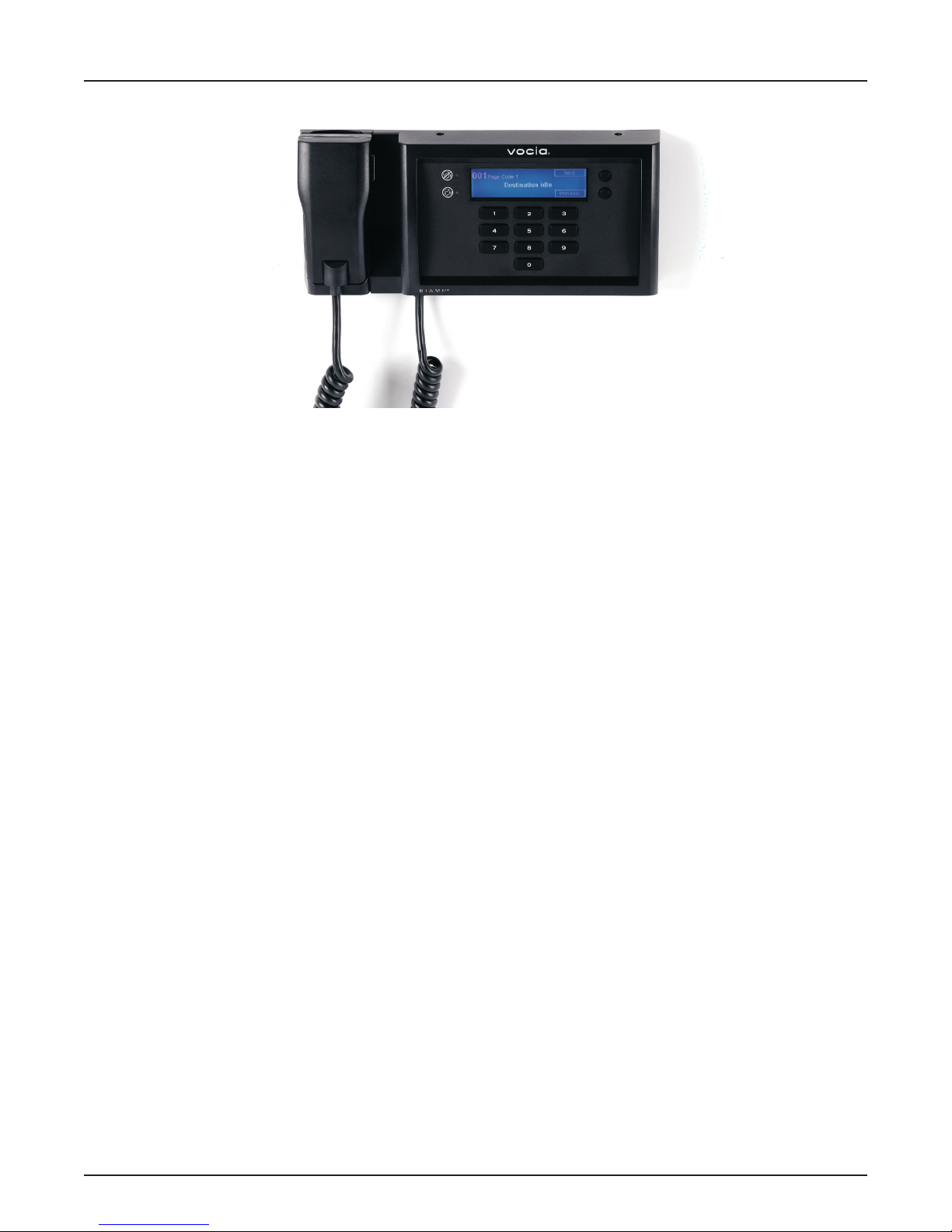
Display Status Messages
The following messages are used to display the state of the WS-10 during normal operation. More information on display status messages
can be found in the Vocia Help File.
1. Destination Idle: This status message indicates that the paging station is ready and there are no busy zones among the destinations
selected by the Page Code.
2. No Network: This status message indicates that the WS-10 is not connected to a functioning network. Please check network
connections and settings.
3. Destination Busy: This status message signies that at least one of the destination zones is busy with a lower priority page.
When paging into a busy zone, the lower priority message will be lost.
4. Destination Delay: This status message indicates that at least one of the destination zones is busy with a page of equal priority.
When paging into a busy zone at an equal priority, the message will be recorded in the WS-10 locally and played when the busy
zones become available.
5. Not Available: This status message indicates that the selected Page Code is not available. The message “Code Barred” or “Undened”
will appear in the top left corner of the display. Please choose a different Page Code or assign the selected Page Code to the WS-10.
6. Please Wait: This status message signies that the PTT button has been pressed and the system is assigning paging resources
and playing the preamble. Simultaneously, the yellow LED below the “Wait” icon will illuminate.
7. Request Failed: This indicates that the PTT button has been pressed and the request has failed. If a recorded message is associated
with this Page Code, please check that an MS-1 is online and congured to play the announcement.
8. Please Talk Now: This status message indicates that the PTT button has been pressed, the page has been correctly set up in the
system, any assigned preamble has nished playing, and the audio path is open. This status message corresponds with the
green LED illuminated below the “Please Talk Now” icon.
9. Request Queued: This status message reports that the selected Page Code represents a request to play a recorded announce-
ment. When the zone(s) are ready to receive the announcement, the message will be played and the WS-10 will return to the
Destination Idle state.
10. Cancel Request?: This status message indicates that the selected Page Code is a Delayed Release page. Once the PTT button
is released, the “Cancel” prompt will ash on the display. The “Cancel Request?” message is displayed for ve seconds. If the user
presses the Cancel button within this ve-second period, the recorded page will be discarded and the system will return to idle
status. If ve seconds elapses and the user does not press the Cancel button, the message will be released for playback as soon
as all destination zones are available.
11. Page Will End in “x” Secs: This status message is displayed when a page termination is imminent (either due to lack of memory
or a timeout). The “x” signies a value in seconds.
12. (EWS-10 Only) Fault: This status messages indicates that a General Fault has been detected in the system.
13. (EWS-10 Only) Alarm: This status message indicates that the system is in Alarm mode.
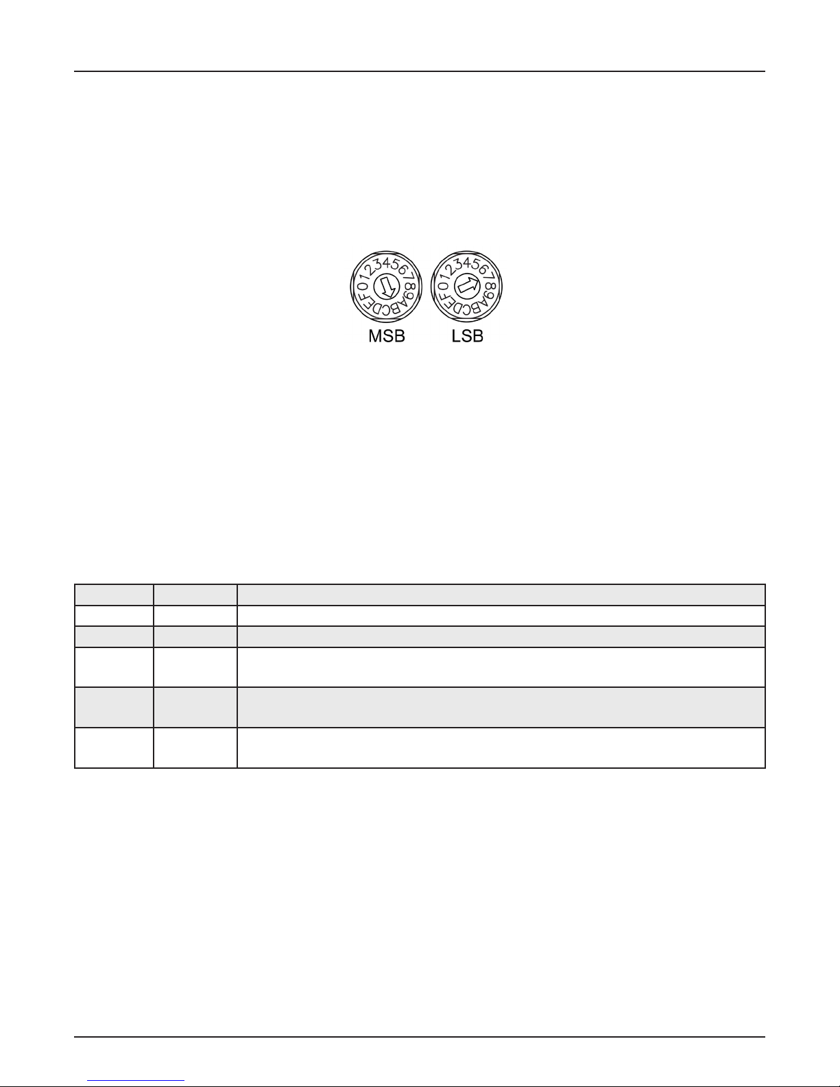
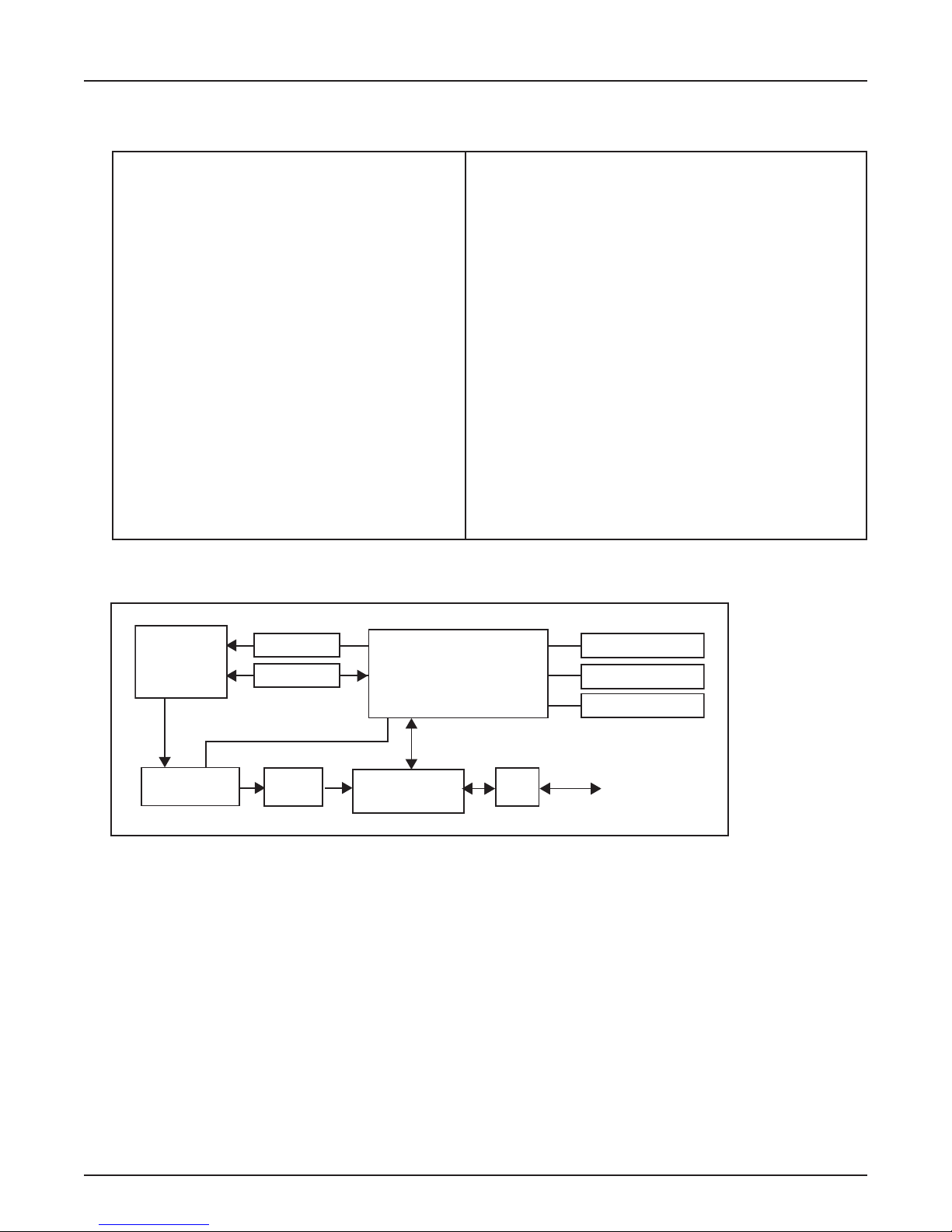
Device Information
To access the device information, such as Device ID, the system time, and the time and date of the last rmware update, please press
and hold down any combination of three of the ten Page Code buttons.
7
WS-10 DISPLAY
Device ID System Time
Time/date of last
Firmware update

8
WS-10 INSTALLATION
Any combination of the screw holes shown in the rear-view diagram can be used to mount the bracket to the wall (do not t a screw
to the hole marked No Screw). A minimum of four screws should be used. Please note: the maximum screw head height is 0.157 inch
(4mm) (dimension from top of installed screw head to inside of mounting bracket). Screws with larger heads may damage the unit. The
paging station must be cabled and its Device ID set before mounting it to the bracket. Please use the four M3 x 8mm countersunk screws
supplied to secure the paging station to the bracket. The following diagrams have been provided for guidance in installing this product.
MAX 4mm (0.157")
5.08
0.200
(
19.50
)
50.55
1.990
0
58
83.50
0
55.46
83.50
0
3
62.13
106.50
122.50
126.53
4.982
7.52
A A
B B
C
L
(0.200 x 1.990) TOOL
R
0.79
R
0.79
R
2
TYPICAL
0
83.50
135.50
241.50
293.50
11.555
0
5
14.71
0.579
SECTION A-A
45°
R
2
TYPICAL
R
4.76
0.188
3.45
0.136
0
3.21
11.50
19.71
0.776
0
37
83.50
94.85
102.85
150.51
164.48
212.51
226.48
0
4.41
19.71
0.776
SECTION B-B
NOTES:
1. MATERIAL AND FINISH INFORMATION FOR MANUFACTURING MUST BE SOURCED FROM THE
'BIAMP SYSTEMS SUPPLIER
INDUSTRIAL DESIGN SPECIFICATIONS'.
2. REFERENCE DIMENSIONS ONLY ARE PROVIDED ON THIS DRAWING. COMPREHENSIVE DIMENSIONS FOR TOOLING AND
MANUFACTURING MUST BE SOURCED FROM THE ASSOCIATED CAD FILE OR DATABASE.
D
E
F
C
1
2
3
4
B
A
3
2
1
5
C
D
4
6
7
8
A
B
A3.4402
SHEET 1 OF 3
DWG NO.
TITLE:
DATE
AMEND
DESCRIPTION
REFERENCE:
Biamp Systems Pty Ltd
Unit 2, 87 Webster Road
Stafford, Queensland, 4053
AUSTRALIA
Phone: (+61)(0)7 3552 9552
Fax: (+61)(0)7 3352 5578
UNLESS OTHERWISE SPECIFIED:
DIMENSIONS ARE IN MILLIMETRES
THIRD ANGLE PROJECTION
TOLERANCES:
LINEAR: +/- 0.1mm
ANGULAR: +/- 0.5
WEN
DO NOT SCALE DRAWING
REVISION
FINISH:
MATERIAL:
DEBUR AND BREAK SHARP EDGES
ISSUE
10
12
13
14
15
16
17
11
BRACKET WS
551.0040.90A
WEIGHT: (grams)
284.13
Vocia
CHECKED: WEN
APPROVED: NTP
551.0040.90A BRACKET WS
REFER NOTE 1
20GA Z-NAL (0.912mm)
THE INFORMATION DISCLOSED HEREIN WAS ORIGINATED BY
AND IS THE PROPERTY OF BIAMP SYSTEMS AND EXCEPT FOR
THE RIGHTS EXPRESSLY GRANTED TO THE UNITED STATES
GOVERNMENT, BIAMP SYSTEMS RESERVES ALL PATENT,
PROPRIETARY, DESIGN USE, SALE, MANUFACTURING AND
REPRODUCTION RIGHTS THERETO.
PT NO.
A
06.04.09
Profile

9
WS-10 SPECIFICATIONS
Wall Station 10 SPECIFICATIONS
FrequencyResponse(electronics): +0,-1dB, 100Hz to 20kHz A/D Converters: 24-bit (48kHz sampling)
Eective Input Headroom: 30dB Connection: RJ45 with shielded Ethernet/PoE cable
(CAT5, CAT5e, CAT6, or CAT7)
Gain: Adjustable in 1dB steps
over a 30dB range
Power:
Aux:
802.3af (PoE) Class 2
24V DC 6W
System Headroom: 18dB Overall Dimensions
(excl. microphone):
Height:
Width:
Depth:
5.3 inches (135mm)
11.9 inches (302mm)
1.9 inches (48mm)
Maximum Input: 125dB SPL Mic Cord Length (extended): 4 ft (1200mm)
THD + N (100Hz to 8kHz): <0.05% Weight: Approx. 2.6 lbs. (1.2kg)
Mic Type: dynamic Ambient Operating
Temperature Range: 32-113 degrees F (0-45 degrees C)
Mic Pattern: noise cancelling cardioid Compliance: EU Directive 2002/95/EC, RoHS directive
CE marked
Mic Frequency Response (1cm): 100Hz-10kHz
Wall Station 10 Block Diagram
Te st Gen
Gain
CobraNet
audio and
control
A/D PoE
CobraNet
Processor
Keypad
LCD
ID Switches
Aux Port
Microphone HostProcessor
585.0254.90A

10
WS-10 MICROPHONE REPLACEMENT
1. Remove microphone from catch. Remove top and bottom screws
from the main body of the wall station with torx screwdriver size 10 (T10).
2. Pull bezel towards you and bend down as shown below.
3. Detach the white microphone connector from the board (and the Ethernet cable if connected).
4. Use a pointed tool to release the catch located to the right of the microphone on the bottom side of the wall station.
Slide the microphone cord to the left and remove the microphone cord.
5. Remove the metal catch from the original microphone.
Place the metal catch on the new microphone cord as shown below.
6. Slide the microphone cable into the groove until the metal catch snaps in.

11
WS-10 MICROPHONE REPLACEMENT
7. Connect the white microphone connector as shown below.
8. Place the front bezel over the wall station and attach the top and bottom screws.

12
WS-10 WARRANTY
BIAMP SYSTEMS IS PLEASED TO EXTEND THE FOLLOWING 5-YEAR LIMITED WARRANTY TO THE ORIGINAL PURCHASER OF
THE PROFESSIONAL SOUND EQUIPMENT DESCRIBED IN THIS MANUAL
1. BIAMP Systems warrants to the original purchaser of new products that the product will be free from defects in material and
workmanship for a period of 5 YEARS from the date of purchase from an authorized BIAMP Systems dealer, subject to the
terms and conditions set forth below.
2 If you notify BIAMP during the warranty period that a BIAMP Systems product fails to comply with the warranty, BIAMP Systems will
repair or replace, at BIAMP Systems’ option, the nonconforming product. As a condition to receiving the benets of this warranty, you
must provide BIAMP Systems with documentation that establishes that you were the original purchaser of the products. Such
evidence may consist of your sales receipt from an authorized BIAMP Systems dealer. Transportation and insurance charges to and
from the BIAMP Systems factory for warranty service shall be your responsibility.
3. This warranty will be VOID if the serial number has been removed or defaced; or if the product has been altered, subjected to
damage, abuse or rental usage, repaired by any person not authorized by BIAMP Systems to make repairs; or installed in any
manner that does not comply with BIAMP Systems’ recommendations.
4. Electro-mechanical fans, electrolytic capacitors, gooseneck microphones, cords connecting handheld microphones, hard-drives,
displays, and normal wear and tear of items such as paint, knobs, handles, keypads and covers are not covered under this
warranty. All server-based devices are warranted for 3 years only.
5. This warranty is in lieu of all other warranties, expressed or implied. BIAMP Systems disclaims all other warranties, expressed
or implied, including, but not limited to, implied warranties of merchantability and tness for a particular purpose.
6. The remedies set forth herein shall be the purchaser’s sole and exclusive remedies with respect to any defective product.
7. No agent, employee, distributor or dealer of BIAMP Systems is authorized to modify this warranty or to make additional warranties
on behalf of BIAMP Systems. Statements, representations or warranties made by any dealer do not constitute warranties by
BIAMP Systems. BIAMP Systems shall not be responsible or liable for any statement, representation or warranty made by any
dealer or other person.
8. No action for breach of this warranty may be commenced more than one year after the expiration of this warranty.
9. BIAMP Systems shall not be liable for special, indirect, incidental, or consequential damages, including lost prots or loss of use
arising out of the purchase, sale, or use of the products, even if BIAMP Systems was advised of the possibility of such damages.

13
COMPLIANCE

14
COMPLIANCE
Table of contents
Other Biamp Microphone manuals

Biamp
Biamp Parlé TTM-X Original operating instructions

Biamp
Biamp Vocia DS-4 User manual

Biamp
Biamp DCM-1 User manual

Biamp
Biamp Vocia PSKIT-1 User manual

Biamp
Biamp Tesira TCM-1 User manual

Biamp
Biamp Vocia VAM-1 User manual

Biamp
Biamp Vocia WS-4 User manual

Biamp
Biamp Vocia PSKIT-1 User manual

Biamp
Biamp NPX H1040 Original operating instructions

Biamp
Biamp Vocia DS-4 User manual