3
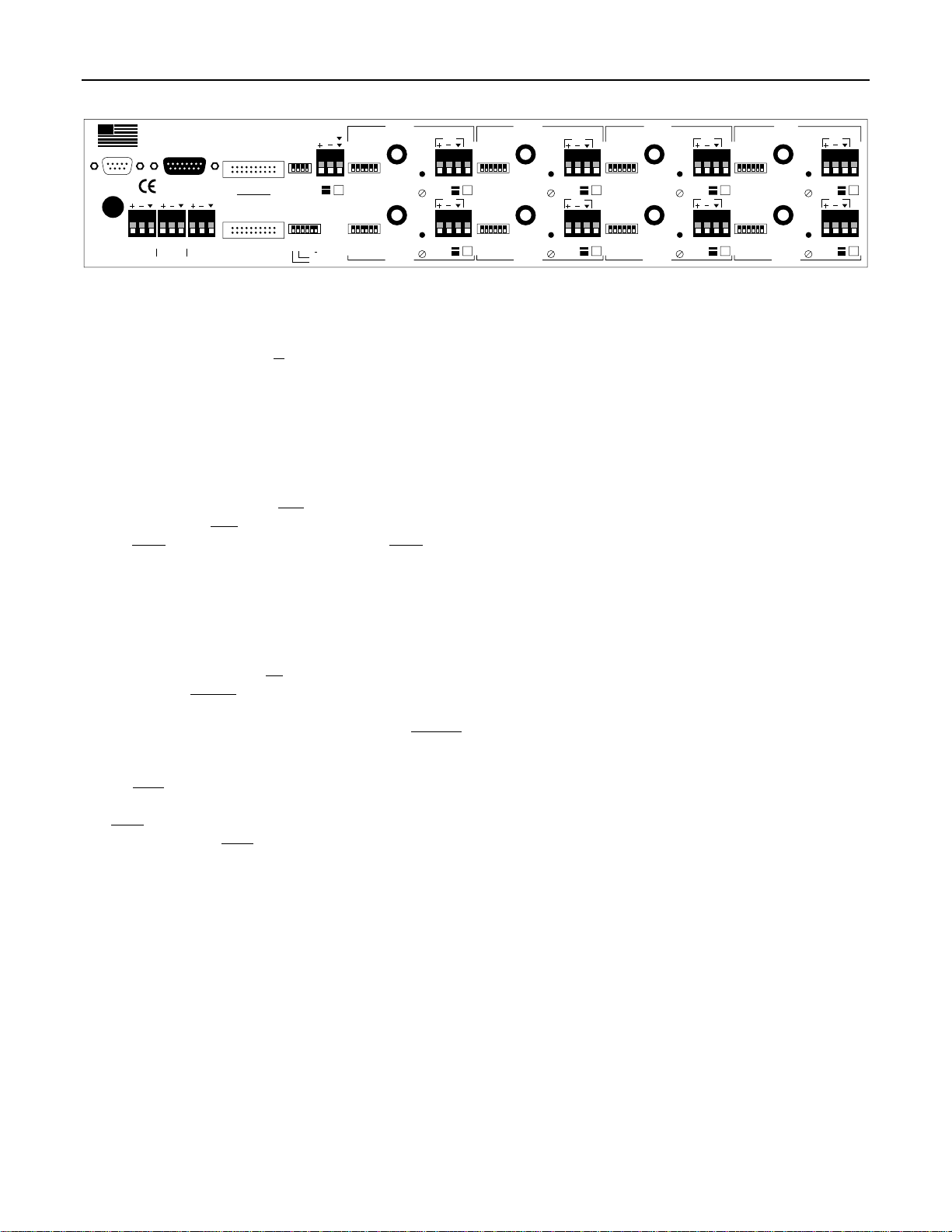
FRONT & REAR PANEL FEATURES
logic
outputs remote
control
expansion out
hpf
main
bus2
bus1
last mic
slave
bus1
1.0 sec
bus2
expansion in
aux 1 aux 2 main
aux input
R
L
patch
trim
+10
trim
+10
patch
trim
+10
trim
+10
patch
patch
trim
+10
trim
+10
patch
trim
+10
trim
+10
pad
off
off
off
off
master
bus2
0.4 sec
bus1
aux 1 select
aux 2 select
output
MADE IN U.S.A.
BIAMP SYSTEMS
Portland, Oregon
an affiliate of Rauland-Borg Corp.
sum
bal
off
CH 7 CH 6
patch
CH 5
patchpatch
CH 4
CH 8
CH 2 CH 1
CH 3
main
bus2
bus1
on
p pwr
off
off
off
off
auto
off hpf
main
bus2
bus1
on
off
off
off
off
auto
off hpf
p pwr
factory defaults
aux1 - bus1 (post gate)
aux2 - bus2 (pre gate)
on
auto
pad
pad
main
bus2
bus1
on
p pwr
off
off
off
off
auto
off hpf
main
bus2
bus1
on
off
off
off
off
auto
off hpf
p pwr
pad
pad
main
bus2
bus1
on
p pwr
off
off
off
off
auto
off hpf
main
bus2
bus1
on
off
off
off
off
auto
off hpf
p pwr
pad
pad
main
bus2
bus1
on
p pwr
off
off
off
off
auto
off hpf
main
bus2
bus1
on
off
off
off
off
auto
off hpf
p pwr
pad
hold time
input
d out
input
d out
input
d out
input
d out
input
d out
input
d out
input
d out
input
d out
class 2 wiring
50/60 Hz
~
27V
27 watts, 1 A
Aux Input & Bal/Sum Switch: This plug-in barrier strip provides
the line-level input to the Aux Channel. The Bal/Sum Switch
selects either balanced (mono) or unbalanced (summing) input.
For balanced input, wire high to (+), low to (-), and ground to (
ý
).
For unbalanced input, wire highs to (L) & (R), and ground to (
ý
).
This can be a stereo signal, two mono signals, or a single mono
signal. Summing combines (L) & (R) into a single mono signal.
Aux DIP Switch: This four-gang DIP switch assigns specific
functions to the Aux Channel. To assign a function, move the
corresponding switch upwards. HPF enables a high-pass filter
(6dB/oct. @ 170Hz). Main sends Aux Channel signal to the Main
output. Bus 2 sends Aux Channel signal to Bus 2. Bus 1 sends
Aux Channel signal to Bus 1.
NOTE: Main, Bus 2, & Bus 1 signals
are affected by the Aux Channel Level control (post-fader).
The
factory default settings are with all DIP switches down.
Master DIP Switches: This six-gang DIP switch assigns specific
functions to the mixer as a whole. To assign a function, move the
corresponding switch upwards. On turns Channels 1~8 on steadily
(automixing off). 1.0 Sec assigns a Hold Time of one second.
Hold Time selects how long an active automix channel will remain
on, once signal is no longer present in the channel. Last Mic
allows the most recently active automix channel to remain on
(without signal present) until the next automix channel becomes
active. Slave sets the mixer as a secondary unit, when linking
multiple mixers within a system (see Expansion Out & Expansion
In). Bus 1 sends the Bus 1 (post-VCA) signal to the Aux 2 output
(see Options on pg. 4). Bus 2 sends the Bus 2 (pre-VCA) signal to
the Aux 1 output (see Options on pg. 4). The factory default
settings are with all DIP switches down.
Expansion Out & Expansion In: These 20-pin headers are for
linking multiple mixers within a system. A 20-pin cable harness is
provided with each mixer. To link mixers, simply connect the cable
harness from Expansion In of one mixer to Expansion Out of the
next mixer. Linking mixers increases input capacity and allows
room combining. The first mixer within a system is assigned as
the ‘master’. The ‘master’ collects audio signals & control data
from the other mixers, which are assigned as ‘slaves’. They in turn
receive appropriate signals & data from the ‘master’. Main, Aux 1,
& Aux 2 output signals, plus NOM attenuation, are common to all
mixers. However, each mixer has independent Output Level,
Remote Control, & Leveling. In room combining applications, the
‘master’/’slave’ assignments are changed via remote switches or
contact-closures (see Remote Control).
Remote Control: This 15-pin Sub-D connector allows remote
control of the mixer. Level control of Channels 1~8, Aux Channel,
Main Ouput, & Aux 1 Output are provided, as well as selection of
automixing & master/slave modes (see Remote Control on pg. 6).
Logic Outputs: This 9-pin Sub-D connector provides Logic
Outputs from Channels 1~8, plus a common ground. When a
channel becomes active, the corresponding Logic Output goes on.
Logic Outputs may be used to control external switching circuits,
such as relays or other Advantage products. These outputs are
typically used to turn off speakers or select cameras when certain
microphones are active (see Logic Outputs on pg. 8).
Main Output: This plug-in barrier strip provides the balanced
Main output from the DLA93. For balanced output, wire high to
(+), low to (-), and ground to (
ý
). For unbalanced output, wire high
to (+) and ground to both (-) & (
ý
). An isolation transformer is
optional for Main Output (see Options on pg. 4). Main Output
signals are always post-VCA from the channels. When multiple
DLA93s are used, Main Output signal is affected by Expansion Out
& Expansion In (see above).
Aux 1 Output: This plug-in barrier strip provides the balanced
Aux 1 output from the DLA93. For balanced output, wire high to
(+), low to (-), and ground to (
ý
). For unbalanced output, wire high
to (+) and ground to both (-) & (
ý
). An isolation transformer is
optional for Aux 1 Output (see Options on pg. 4). Aux 1 Output
signals are normally post-VCA from the channels, but may be
changed to pre-VCA (see Master DIP Switches above, and
Options on pg. 4). When multiple DLA93s are used, Aux 1 Output
signal is affected by Expansion Out & Expansion In (see above).
Aux 2 Output: This plug-in barrier strip provides the balanced
Aux 2 output from the DLA93. For balanced output, wire high to
(+), low to (-), and ground to (
ý
). For unbalanced output, wire high
to (+) and ground to both (-) & (
ý
). Aux 2 Output signals are
normally pre-VCA from the channels, but may be changed to post-
VCA (see Master DIP Switches above, and Options on pg. 4).
When multiple DLA93s are used, Aux 2 Output signal is affected
by Expansion Out & Expansion In (see above).
AC Power Cord: The transformer provides 27 VAC (1A max.) to
the DLA93, and is detachable via a 5-pin DIN connector. If blown,
two internal ‘self-resetting’ fuses will attempt to re-set after a short
period. Continued blowing of these fuses may be an indication
that the DLA93 requires service.