manuals.online logo
Brands
  1. Home
  2. •
  3. Brands
  4. •
  5. Biamp
  6. •
  7. Mixer
  8. •
  9. Biamp VRAM User manual

Biamp VRAM User manual

Other Biamp Mixer manuals

Biamp 801I User manual

Biamp

Biamp 801I User manual

Biamp 801I User manual

Biamp

Biamp 801I User manual

Biamp IWA250 User manual

Biamp

Biamp IWA250 User manual

Biamp MIXPAK PLUS User manual

Biamp

Biamp MIXPAK PLUS User manual

Biamp DJ5600 User manual

Biamp

Biamp DJ5600 User manual

Biamp ADVANTAGE DP/M 28 User manual

Biamp

Biamp ADVANTAGE DP/M 28 User manual

Biamp ADVANTAGE 601e User manual

Biamp

Biamp ADVANTAGE 601e User manual

Biamp RPM SERIES User manual

Biamp

Biamp RPM SERIES User manual

Biamp autoTWO User manual

Biamp

Biamp autoTWO User manual

Biamp 801 User manual

Biamp

Biamp 801 User manual

Biamp ADVANTAGE SPM522D User manual

Biamp

Biamp ADVANTAGE SPM522D User manual

Biamp 301 User manual

Biamp

Biamp 301 User manual

Biamp SCM 7600 User manual

Biamp

Biamp SCM 7600 User manual

Biamp AUTOONE User manual

Biamp

Biamp AUTOONE User manual

Biamp 44 User manual

Biamp

Biamp 44 User manual

Biamp IWA SERIES User manual

Biamp

Biamp IWA SERIES User manual

Biamp IWA250 User manual

Biamp

Biamp IWA250 User manual

Biamp DJ 5600 User manual

Biamp

Biamp DJ 5600 User manual

Biamp advantage DLA93 User manual

Biamp

Biamp advantage DLA93 User manual

Biamp RACKMAX II User manual

Biamp

Biamp RACKMAX II User manual

Popular Mixer manuals by other brands

Oster FPSTSM2710 instruction manual

Oster

Oster FPSTSM2710 instruction manual

Aviom A-16II user guide

Aviom

Aviom A-16II user guide

Varimixer V30K Spare part and operation manual

Varimixer

Varimixer V30K Spare part and operation manual

Kohler Stillness K-T954 installation guide

Kohler

Kohler Stillness K-T954 installation guide

Wolf Gourmet WGSM300 Use & care guide

Wolf Gourmet

Wolf Gourmet WGSM300 Use & care guide

Team International TEAM MS 17 operating instructions

Team International

Team International TEAM MS 17 operating instructions

MULTIQUIP Whiteman WM45E Operation and parts manual

MULTIQUIP

MULTIQUIP Whiteman WM45E Operation and parts manual

KitchenAid KSM7581BZ0 Instructions and recipes

KitchenAid

KitchenAid KSM7581BZ0 Instructions and recipes

Jay-Lor 5050 owner's manual

Jay-Lor

Jay-Lor 5050 owner's manual

privileg MJ-BL1051W user manual

privileg

privileg MJ-BL1051W user manual

Fakir CULINA CHEF user manual

Fakir

Fakir CULINA CHEF user manual

Termozeta Bellacucina Instruction booklet

Termozeta

Termozeta Bellacucina Instruction booklet

Thinky ARE-250 instruction manual

Thinky

Thinky ARE-250 instruction manual

Midas XL4 manual

Midas

Midas XL4 manual

bianco PURO 4 manual

bianco

bianco PURO 4 manual

better chef IM-815WC Use and care book

better chef

better chef IM-815WC Use and care book

ALLEN & HEATH GR1 user guide

ALLEN & HEATH

ALLEN & HEATH GR1 user guide

Buffalo CP921 instruction manual

Buffalo

Buffalo CP921 instruction manual

manuals.online logo
manuals.online logoBrands
  • About & Mission
  • Contact us
  • Privacy Policy
  • Terms and Conditions

Copyright 2025 Manuals.Online. All Rights Reserved.

VRAM
Variable Resource
Automixer
Operation Manual
Biamp Systems, 10074 S.W. Arctic Drive, Beaverton, Oregon 97005 U.S.A. (503) 641-7287 www.biamp.com
an affiliate of Rauland Borg Corp.
print update
September 7, 2005
blank
1
VRAM
TABLE OF CONTENTS
Front & Rear Panel Features
Setup
Logic Inputs
Logic Outputs
RS-232 Control
Specifications & Block Diagram
Warranty
pgs. 2 & 3
pgs. 4~9
pgs. 10 & 11
pgs. 12 & 13
pgs. 14 & 15
pg. 16
INTRODUCTION
The VRAM Variable Resource Automixer is a 10-in / 2-out programmable
automatic mixer, which is completely user tamper proof, providing no external
controls. All mixer parameters are under microprocessor control, and are
easily programmed via Windows®software. The VRAM is extremely versatile,
with an extensive set of features, and is designed to adapt to a variety of
applications. A second model, VRAMeq, includes 3-band channel
equalization, with variable mid-frequency. The VRAM is covered by a five-year
warranty.
VRAM features include:
♦8 balanced mic/line inputs on plug-in barrier strip connectors
♦2 balanced auxiliary line inputs on plug-in barrier connectors
♦balanced main & aux outputs on plug-in barrier connectors
♦phantom power, trim, HPF, level, & gating on channels 1~8
♦model VRAMeq includes 3-band, variable-mid, channel EQ
♦aux line inputs include mix-minus & teleconferencing mode
♦independent mixing to main & aux outputs (pre/post gate)
♦direct outputs from channels (programmable pre/post gate)
♦eight logic outputs (programmable timing & pre/post gate)
♦eight logic inputs (programmable for remote switch control)
♦sixteen non-volatile memory presets store all mixer settings
♦NOM attenuation, last mic, default mic, & hold time selectable
♦selectable channel-off gating attenuation (-10dB to -80dB)
♦expansion in & out for linking of units for more mixer inputs
♦controls & indicators provided by software graphic interface
♦software peak & level meters - front panel active indicators
♦Windows®95/98/NT/2000/XP software & cable included
♦remote control via RS-232 & programmable logic inputs
♦incorporates AES recommended grounding practices
♦marked and UL / C-UL listed power source
♦covered by Biamp Systems' five-year warranty
2
FRONT & REAR PANEL FEATURES
12345678
on
VRAM
FRONT PANEL FEATURES
Channel Gate Indicators: These red LEDs normally indicate
when Channels 1~8 are active to Main Out (‘on’ or ‘auto’ gating).
NOTE: When a channel is assigned as ‘off’ to Main Out, but is
assigned as ‘auto’ to Aux Out, this indicator will light when the
channel is active (gated on) to Aux Out (see Setup on pg. 5).
On Indicator: When AC power is applied to the VRAM, this red
LED will light indicating power to the mixer is On. When power is
removed, all ‘current mix’ settings (levels, assignments, etc.) will
be stored in non-volatile memory and recalled when power is
restored. NOTE: During setup the VRAM may instead be set to
recall a special preset whenever power is turned on (see Setup on
pg. 9).
REAR PANEL FEATURES
AC Power Cord: The power transformer provides 27 Volts AC to
the VRAM, and is detachable via a 5-pin DIN connector. The
VRAM has two internal ‘self-resetting’ fuses (there are no user
serviceable parts inside the unit). If the internal fuses blow, they
will attempt to re-set after a short period. However, this may be an
indication that the VRAM requires service.
Serial Port: This 9-pin Sub-D (male) connector provides an RS-
232 Serial Port for remote control via computer or third-party
controllers (see RS-232 Control on pg. 14). The Serial Port has
the following pin assignments (left-to-right & top-to-bottom): Pin 1)
not used; Pin 2) Receive Data (RxD) input; Pin 3) Transmit
Data (TxD) output; Pin 4) Data Terminal Ready (DTR) output;
Pin 5) Ground; Pin 6) not used; Pin 7) Request To Send (RTS)
output; Pin 8) not used; Pin 9) not used. BiampWin software
and a null-modem cable are provided for programming (see Setup
on pg. 4). NOTE: The Serial Port can also transmit commands
received via the Logic Inputs (see Setup on pg. 8).
Link Port: This 9-pin Sub-D (female) connector provides a Link
Port for RS-232 control of multiple BIAMP products (see RS-232
Control on pg. 14). The Link Port of one device simply connects to
the Serial Port of the next device (and so forth). Link cables are
available as an option (Biamp #909-0057-00). NOTE: All but the
final device in a system should have the Link Switch pressed in
(see below). The Link Port has the following pin assignments
(right-to-left & top-to-bottom): Pin 1) not used; Pin 2) Transmit
Data (TxD) output; Pin 3) Receive Data (RxD) input; Pin 4) not
used; Pin 5) Ground; Pin 6) not used; Pin 7) not used; Pin 8)
not used; Pin 9) not used. NOTE: The Link Port will also
transmit commands received via the Logic Inputs (see Setup on
pg. 8).
Link Switch: The Link Switch is used when connecting multiple
devices in a ‘Link Port to Serial Port’ configuration (see Link Port
above). From the factory, the Link Switch is released (out). When
connecting multiple devices, the Link Switch must be depressed
(in) on all devices except the final device in the system (the device
with no Link Port connection).
3
FRONT & REAR PANEL FEATURES
outputs auxiliary inputs
auxmain aux 2 aux 1
50/60 Hz
27 watts
class 2 wiring
~
27V
link port link expansion
serial port
logic inputs
logic outputs
out
in
channel 8
input
d. out
channel 7
input
d. out
channel 6
input
d. out
channel 5
input
d. out
channel 4
input
d. out
channel 3
input
d. out
channel 2
input
d. out
channel 1
input
d. out
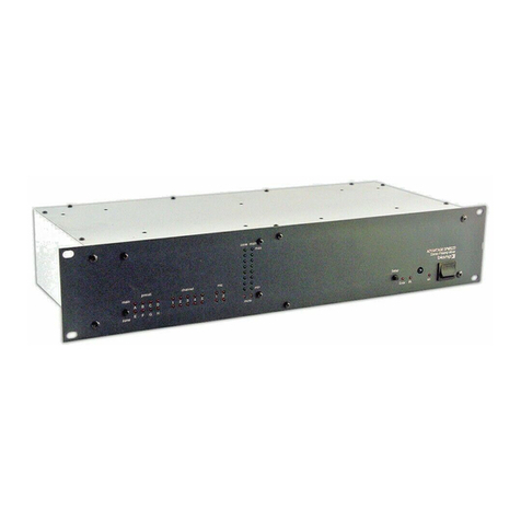
Logic Outputs: This 9-pin Sub-D connector provides Logic
Outputs from Channels 1~8 (see Logic Outputs on pg. 12). If a
channel is assigned as ‘auto’ to either Main Out or Aux Out, the
corresponding Logic Output will turn on whenever the channel is
gated on. Logic Outputs may be used to control external switching
circuits, such as relays or other BIAMP products. These outputs
are typically used to turn off speakers or select cameras when
certain microphones are active. NOTE: Individual Logic Outputs
may be turned on/off via software or remote control. However, this
temporarily defeats their ability to follow the active channel, until
again assigned to ‘follow gate’ (see Setup on pg. 5).
Logic Inputs: This 9-pin Sub-D (female) connector provides eight
logic inputs for controlling the VRAM via contact-closures (see
Logic Inputs on pg. 10). Logic Inputs are programmed using the
BiampWin software and serial cable provided with the VRAM (see
Setup on pg. 8). NOTE: From the factory, Logic Inputs 1~8 have
no pre-programmed function.
Expansion In & Out: These 6-pin mini-DIN connectors are for
linking multiple mixers, to increase the number of input channels.
A 6-pin mini-DIN cable is provided with each mixer. To link mixers,
simply connect the cable from the Expansion Out jack of one mixer
to the Expansion In jack of the next mixer (and so forth). The final
mixer in the system (with no Expansion Out jack connection)
becomes the ‘master’. The ‘master’ collects audio signals &
control data from the other mixers, which become ‘slaves’. Main
Out & Aux Out signals, plus NOM attenuation, for the combined
system are provided by the ‘master’. The outputs from ‘slave’
mixers provide only signals from their own inputs, plus those of
any ‘slave’ mixers connected to them via Expansion In.
Main Out: This plug-in barrier strip provides the balanced Main
Out from the VRAM. For balanced output, wire high to (+), low to
(-), and ground to (d). For unbalanced output, wire high to (+) and
ground to (d), leaving (-) unconnected. Signal level will be
reduced by 6dB when outputs are unbalanced.
Aux Out: This plug-in barrier strip provides the balanced Aux Out
from the VRAM. For balanced output, wire high to (+), low to (-),
and ground to (d). For unbalanced output, wire high to (+) and
ground to (d), leaving (-) unconnected. Signal level will be
reduced by 6dB when outputs are unbalanced.
Aux 1 & Aux 2 Inputs: These plug-in barrier strips provide the
balanced auxiliary line inputs to the VRAM. For balanced input,
wire high to (+), low to (-), and ground to (d). For unbalanced
input, wire high to (+) and ground to both (-) & (d).
Channel Input & Direct Output: These plug-in barrier strips
provide the balanced mic/line input to the respective channels. For
balanced input, wire high to (+), low to (-), and ground to (d). For
unbalanced input, wire high to (+) and ground to both (-) & (d).
Unbalanced Direct Outputs are also available from the channels
using (d out) & (d). NOTE: Inputs & Direct Outputs can be
assigned for ‘auto’ (gated) or on/off operation (see Setup on pg. 5).
4
SETUP
VRAM & VRAMeq parameters are all adjustable using the 'BiampWin' software and null-modem cable provided with the unit. BiampWin
software provides programs for various BIAMP products, including the VRAM(eq). The VRAM program includes seven control screens,
which are described on the following pages. Once the software is started (and Comm Port Configuration is set), the control screens are
accessed via the drop-down menus at the top of the opening screen. The Mix screen appears whenever a VRAM file is opened. Channel
Settings, Automixer Settings, Button Definitions, Logic Input Definitions, Logic Output Polarity, & Configuration Options screens are then
available from the Configure VRAM menu. The File menu provides functions such as save, open, download, etc. The Settings menu
recalls the Comm Port Configuration screen. The Window menu arranges the active product screens. The Help menu explains the
available adjustments. To install BiampWin software: Select ‘Run’ from ‘Start’ menu, and browse to 'BiampWin' on appropriate drive.
System Requirements: Windows®95/98/NT/2000/XP with 8MB of available hard disk space (serial port required for ‘on-line’ operation).
MIX SCREEN
The Mix Screen is used to adjust VRAM input/output levels, as well as to store/recall sixteen memory presets. All VRAM inputs may be
adjusted to each output independently. Each output is also independently adjusted. Adjustments are made with the computer mouse (or
keyboard). Input & output levels are adjusted by dragging the corresponding ‘faders’ up or down. Mute buttons turn off the respective
input/output signals, without changing the channel assignments (see next page). Mix Bus meters display ‘pre-fader’ signal levels for the
respective outputs. Main Output & Aux Output meters display ‘post-fader’ signal levels for the respective outputs. NOTE: For best
performance, adjust faders so the meters show occasional peaks in the yellow area, but never to the top (red). Peak indicators should
flash only on occasional peaks in signal level, as determined by input gain adjustments (see pg. 5). Logic Outputs indicators will light
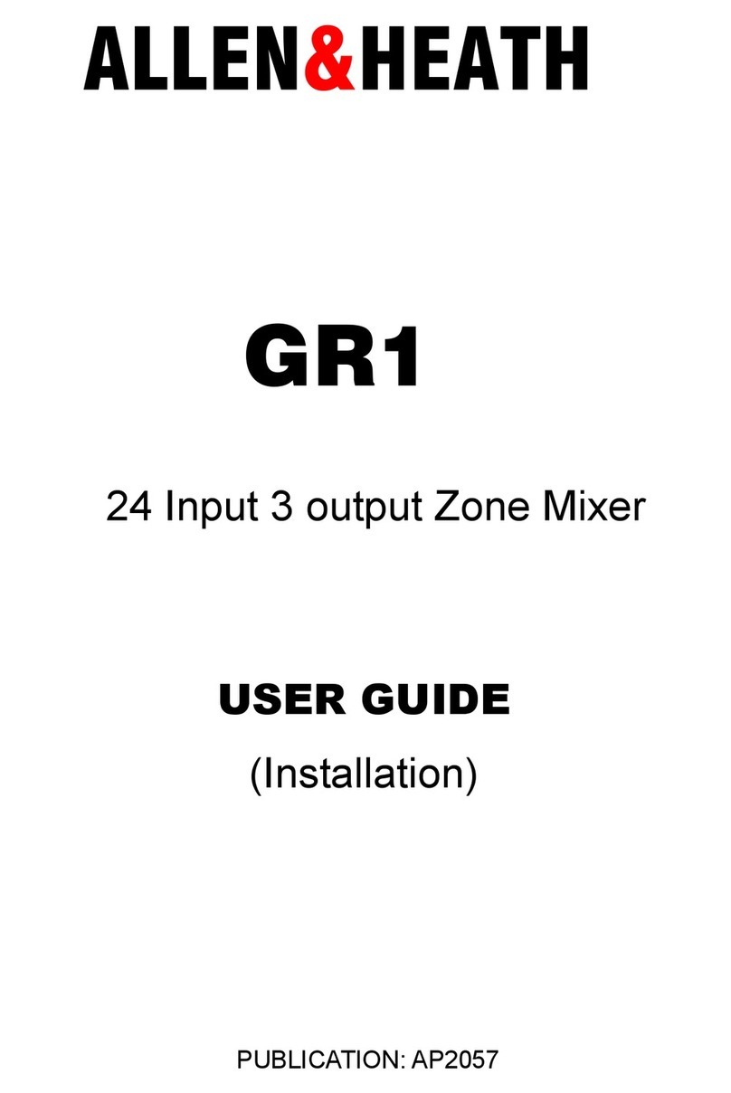
whenever the respective Logic Outputs are on (see pg. 5). Gate indicators will light whenever channels are active to the corresponding
outputs (see pg. 5). Channel Settings selects a screen for adjusting individual input parameters (see pg. 5). Automixer Settings selects a
screen for adjusting automatic mixing functions, which affect the entire mixer (see pg. 6). Preset buttons recall the corresponding presets
from non-volatile memory. Presets must first be created & stored by the user (no factory presets). The Store button opens a menu for
storing current settings in any of the Presets 1~16. Each preset includes settings from the Mix screen, as well as from the Channel
Settings & Automixer Settings screens (see pgs. 5 & 6). The title bar across the top of the Main screen will indicate the Device #, the
custom Device Name, and the model of product being controlled. BiampWin software can operate ‘off-line’ (with no product connected) by
opening a ‘new’ file for the desired product. The Device # for ‘off-line’ files is assigned sequentially as a negative number.
5
SETUP
CHANNEL SETTINGS SCREEN
The Channel Settings screen appears as an overlay of the Mix screen, and is used to adjust individual input parameters. It is accessed via
the Configure VRAM menu, or from the Mix screen. Individual tabs are provided for Channels 1~8 and the Aux Inputs. Right-clicking the
blank area at the upper-left of a tab allows that input to be given a custom name. Gain adjusts the input to compensate for different signal
levels. Set Gain so the Peak indicator flashes only on occasional peaks in signal level. High Pass Filter reduces low frequencies signals
6dB/octave @ 110Hz. Phantom Power turns on +36V power for condenser mics. Low, Mid, & High (model VRAMeq only) provide 3-band
input equalization, with variable mid frequency & bypass. Faders & Mute provide the same functions as on the Mix screen, except that
Main & Aux faders may be Ganged for combined control. Channel Assignment allows the input to be assigned as ‘on’, ‘off’, or ‘auto’ to
Main Out & Aux Out independently. NOTE: ‘Auto’ means automatic gating (signal activated). ‘On’ means not gated (always active). ‘Off’
means unassigned (never active). Direct Out provides ‘on’, ‘off’, or ‘follow gate’ assignment. NOTE: ‘Follow gate’ means to turn on & off
simultaneously with any channel gating (to Main Out or Aux Out). Logic Output provides the same ‘on’, ‘off’, or ‘follow gate’ assignment.
Turn On Delay selects the timing between when a channel becomes active (gate on) and when the corresponding Logic Output turns on.
Turn Off Delay selects the timing between when a channel becomes inactive (gate off) and when the corresponding Logic Output turns off.
NOTE: Logic Output delay times are typically used for proper timing in applications where camera switching circuits are being controlled.
The Aux Inputs tab provides two Gain settings (+6dB & -6dB), and faders for Main Out & Aux Out. Each of the Aux Inputs may be given a
custom name. Aux 1 includes a Teleconference Mode, which defeats the Aux Out fader (mix-minus), and enables a Threshold fader
(Adaptive Threshold Sensing). In this mode Aux 1 provides the teleconference input, and Aux Out provides the teleconference output.
NOTE: Automixer Settings, Presets, & output faders (on the Mix screen) are still available while using the Channel Settings screen.
6
SETUP
AUTOMIXER SETTINGS SCREEN
The Automixer Settings screen is used to adjust automatic mixing functions, which affect the entire mixer. It is accessed via the Configure
VRAM menu, or from the Mix screen. Channel Off Attenuation selects the amount of attenuation applied to ‘auto’ channels when they are
inactive (gated off). NOTE: Channel Off Attenuation is set separately for Main Out & Aux Out. Gate Hold Time selects the length of time
that ‘auto’ channels will remain active (gated on) once signal is no longer present. Max Number of Open Mics limits the quantity of ‘auto’
channels which can be active (gated on) to Main Out at the same time. Designated Mic On / Last Mic Hold selects the most recently active
‘auto’ channel to remain active (gated on), or a specified channel to become active (gated on), whenever signals are no longer present.
Logic Outputs Follow Designated Mic / Last Mic Hold causes logic outputs to turn on when corresponding channels are activated (gated
on) due to their assignment as Designated Mic On or Last Mic On. Direct Outputs Follow Designated Mic / Last Mic Hold causes direct
outputs to turn on when corresponding channels are activated (gated on) due to their assignment as Designated Mic On or Last Mic On.
NOTE: If Logic Outputs or Direct Outputs are not assigned to follow Designated Mic / Last Mic Hold, they will still follow normal gating
activity of the channels, but will not hold without signal (as Last Mic Hold) and will not turn on without signal (as Designated Mic On).
Manual Mode defeats the channel gating functions, turning all channels on to Main Out & Aux Out (except for channels specifically
assigned as ‘off’). Disable NOM Attenuation defeats the typical attenuation (3dB for each doubling of active ‘auto’ channels) which occurs
at Main Out. Help provides additional instruction. Close will close the Automixer Settings screen.
7
SETUP
BUTTON DEFINITIONS SCREEN
The Button Definitions screen is used to assign specific ‘actions’ to remote control buttons. Although the VRAM does not accept
commands from push-button remote controls directly, it can receive individual ASCII characters (via RS-232) from other BIAMP products
and/or third-party control systems. From the factory, Remote Control Buttons have equivalent ASCII characters permanently assigned to
them (see RS-232 Control on pg. 14). Therefore, a Remote Control Button can be assigned specific ‘actions’, which the VRAM will then
perform whenever the equivalent ASCII character for that button is received. From the factory, Remote Control Buttons have no pre-
programmed functions. However, using the Button Definitions screen, each Remote Control Button may be assigned various ‘actions’.
Remote Control Buttons select which button is to be defined. Equivalent ASCII Character displays the permanent ASCII character for the
selected button. Store Preset allows store actions for Presets 1~16 to be assigned to the selected button. Recall Preset allows recall
actions for Presets 1~16 to be assigned to the selected button. Logic Outputs allows ‘on’, ‘off’, & ‘toggle’ actions for Logic Outputs 1~8 to
be assigned to the selected button. NOTE: Turning a Logic Output on/off will temporarily defeat its ability to follow channel gating activity,
until again assigned to 'follow gate’ (see pg. 5). Echo Character displays the ‘echo’ character for the selected button. NOTE: Echo

Characters are permanent for Remote Control Buttons, and can only be changed for Logic Input control (see next page). Main Volume &
Aux Volume allow specific volume & muting actions for Channels 1~8, Aux 1 & 2, Main Out, & Aux Out to be assigned to the selected
button. Clear allows all actions assigned to the selected button (or all buttons) to be cleared. Try It causes the actions currently assigned
to the selected button to be performed by the VRAM. Help provides additional instruction. Close will close the Button Definitions screen.
8
SETUP
LOGIC INPUT DEFINITIONS SCREEN
The Logic Input Definitions screen is used to assign specific ‘actions’ to the Logic Inputs (and remote control buttons). Logic Inputs allow
remote control of the VRAM via external circuits, such as switches, contact-closures, active driver circuits, and/or ‘open-collector’ logic
outputs (see Logic Inputs on pg. 10). From the factory, Logic Inputs 1~8 have no pre-programmed functions. However, using the Logic
Input Definitions screen, each Logic Input may be assigned various ‘actions’. Logic Inputs select which Logic Input is to be defined.
NOTE: Since Logic Inputs are controlled by switches, contact-closures, etc., each Logic Input may be assigned certain actions to perform
when the switch is ‘opened’, and different actions to perform when that same switch is ‘closed’. Store Preset allows store actions for
Presets 1~16 to be assigned to the selected Logic Input. Recall Preset allows recall actions for Presets 1~16 to be assigned to the
selected Logic Input. Logic Outputs allows ‘on’, ‘off’, & ‘toggle’ actions for Logic Outputs 1~8 to be assigned to the selected Logic Input.
NOTE: Turning a Logic Output on/off will temporarily defeat its ability to follow channel gating activity, until again assigned to 'follow gate’
(see pg. 5). Echo Character allows the ‘echo’ character for the selected Logic Input to be changed. NOTE: This is the RS-232 ASCII
character which will be transmitted via the Serial Port whenever that Logic Input is switched. From the factory, no echo characters are
assigned to Logic Inputs 1~8. Changing the Echo Character is used primarily for customizing remote control commands amongst various
RS-232 controlled products within a system (see RS-232 Control on pg. 14). Main Volume & Aux Volume allow specific volume & muting
actions for Channels 1~8, Aux 1 & 2, Main Out, & Aux Out to be assigned to the selected Logic Input. NOTE: Although Logic Inputs
volume actions include a ‘repeating’ (volume ramp) function, they will not continuously repeat the echo character via RS-232. Clear allows
all actions assigned to the selected Logic Input (or all Logic Inputs) to be cleared. Try It causes the actions currently assigned to the
selected Logic Input to be performed by the VRAM. Help provides additional instruction. Close will close the Button Definitions screen.