DDEESSCCRRIIPPTTIIOONN
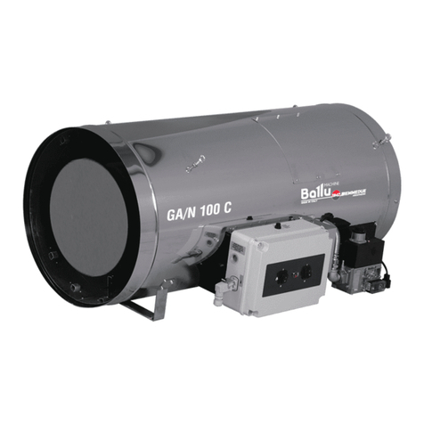
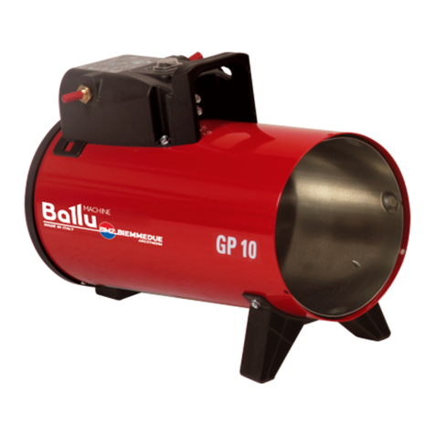
The GA/N hot air generator is designed for heating medium and
large ventilated premises, for which a fixed or mobile heating system is
required.
GA/N heater is to be run on heating with natural gas or L.P.G. ac-
cording to gas supply pressures that must be in conformity with the
national laws.
Gases to be used are indicated in Tab. I together with the supply
pressures, the regulation of the gas valves group (burner pressure) and
gas flow.
The GA/N heater is supplied after a complete functional test and
it’s therefore prearranged for one of the working gas indicated in Tab. I:
an adhesive label applied on the gas selector valve (a) indicates the se-
lected gas. To change the type of gas, follow the detailed instructions
indicated in section “C ANGING TYPE OF GAS”.
The GA/N heater is of the direct combustion type. The air is heated
by the energy developed during combustion and then conveyed to the
environment to be heated together with the combustion products, thus
making available 100% of the thermal power produced. The environ-
ment must be suitably ventilated in order to ensure adequate air circu-
lation.
In the event of serious malfunction various safety devices (electro-
nic flame control unit, overheating thermostat, air pressure switch)
trigger turning off the heater.
The electronic flame control unit monitors if the flame is irregular
or goes out, the safety thermostat triggers when the temperature in the
combustion chamber exceeds the safety limit value, the air pressure
switch will cut in if the airflow is insufficient and the gas pressure swit-
ch will cut in if the gas supply pressure is too low. In each of the said
cases the lamp (8) will light up and the heater will stop working. The
heater can be restarted only by pressing the reset button (8). Nonethe-
less, the cause that triggered the safety device should always be care-
fully analyzed and resolved before restarting the generator (cfr.
“FAULTS, CAUSES AND REMEDIES”).
GGEENNEERRAALL AADDVVIICCEE
Installation, setting and use of the heater must be effected in accor-
dance with the applicable regulations and laws relating to machine use.
The space heater can be installed suspended from the ceiling by
means of cables and/or chains of suitable size and length to fix to the 4
suspension hooks.
Warning
Make sure that the cables and/or chains form a maxi-
mum angle of 5° off vertical on the ceiling.
Warning
Check with your local fire safety authority if you have
questions about applications
ere are a few guidelines which shall be followed:
• The instructions in this manual are carefully followed;
• Minimum clearances from combustible material must be:
1 m (3 feet) from side and rear (air inlet) of heater
0.7 m(2 feet) from ceiling
3 m (10 feet) on air outlet of heater.
• eater shall not be directed toward any propane-gas container
within 6 m (20 feet) and minimum clearances from gas cylinder
must be 3 m (10 feet)
• Don’t install the heater in places where there may be a risk of fire
or explosion
• All fire prevention regulations must be adhered to.
• The GA/N heater is not ductable and shall not be connected to
any ductwork for air distribution.
• The room or building which is being heated must be sufficiently
ventilated so that the heater has enough air to function properly;
• The air suction and/or supply pipes are not blocked in any way,
there are not sheets or covers resting on the machine or walls
and bulky objects near the heater;
• The generator is placed near a power switchboard having specifi-
cations in conformity with those declared;
• The unit is placed in a fixed position;
• The generator is regularly monitored during operation and
checked before being started up;
• Don’t let animals or children near the heater.
• Make sure heater is inspected before each use, and at least an-
nually by a qualified service person.
• After use make sure the disconnecting switch is off.
When using any type of heater it is obligatory:
• not to exceed the maximum level of heat output of the furnace
(“TEC NICAL SPECIFICATION TABLE”);
• to make sure that there is adequate air circulation and air supply
to the heater and that nothing is obstructing the aspiration and
expulsion of air; movement of air may be obstructed in various
ways including placing covers or other objects on the heater or
positioning the heater too near a wall or other large object. If the
airflow is not adequate, the combustion chamber will overheat
and the overheat thermostat will turn the burner off (“OB-
SERVED FAULTS, CAUSES AND REMEDIES”).
IINNSSTTAALLLLAATTIIOONN IINNSSTTRRUUCCTTIIOONNSS
Warning
All the operations described in this paragraph must be
performed by professional and skilled personnel only
The installation shall be in accordance with National Fuel Gas Code
ANSI Z223.1/NFPA 54 and with CAN1-B149.1 or .2 Installation code.
An approved manual gas valve shall be provided by the installer.
ELECTRICAL C NNECTI NS
Warning
The equipment is fitted with a temporar power cable,
used for the final control test at factor .
Warning
the temporar power cord must be removed and replaced
with a proper power cord whose t pe and dimension
shall be in accordance with national rules.
Warning
The power line of the generator must feature an earth
lead and a residual current circuit breaker.
The supply cable must be connected to a switchboard
with sectioning switch.
Every heater is supplied along with the safety and control devices
which are indispensable to the correct functioning of the unit being al-
ready electrically connected.
Warning
Electrical grounding shall be in compliance with the Na-
tional Electrical Code ANSI/NFPA 70 or the CSA C22.1
Canadian Electrical Code, Part I.
The following operations must now be carried out:
• Plug in the power cord having read the rating plate that specify
electric supply characteristics.
• Connect accessories such as the room thermostat or clock to the
unit’s control panel with the thermostat receptacle.
aving completed all these operations check carefully that all elec-
trical connections correspond to the wiring diagram. When the heater
is first turned on you must check that the fan does not use more cur-
rent than the maximum permitted limit.
GAS LINE C NNECTI NS
The connection to the gas feed pipe, whose sizes must correspond
to the kind of system to be made, must be carried out
4
EN
