BIEMMEDUE SUSETTE User manual

GP
G
P
GP
SUSETTE
IDROPULITRICI AD ALTA PRESSIONE
HIGH PRESSURE WATER CLEANERS
MANUALE D’USO E MANUTENZIONE
INSTRUCTIONS MANUAL
By-pass - Total stop Ed. 10/01

COSTRUTTORE BIEMMEDUE S.p.A.
MANUFACTURER Via Industria, 12
12062 Cherasco (CN) - ITALIA
Tel. ++39 0172 486111 - Fax ++39 0172 488270
INTERNET http://www.biemmedue.com
email: [email protected]
MODELLI SUSETTE 120M, SUSETTE 120T, SUSETTE 150T, SUSETTE 170T
MODELS SUSETTE 120M ts, SUSETTE 120T ts, SUSETTE 150T ts, SUSETTE 170T ts
Prima di usare l’idropulitrice, si prega di leggere con attenzione tutte le istruzioni d’uso riportate di seguito e di seguirne scrupolosamente le indicazioni.
Il costruttore non è responsabile per danni a cose e/o persone derivanti da uso improprio dell’apparecchio.
Before using the water cleaner, read and understand all instructions and follow them carefully.
The manufacturer is not responsible for damages to goods or persons due to improper use of the unit.
Ed. 06/01
2
1INTERRUTTORE MAGNETO - TERMICO, IG
MAGNETO - THERMAL SWITCH, IG
2INTERRUTTORE BRUCIATORE, IB
BURNER SWITCH, IB
3MANOPOLA DI REGOLAZIONE TERMOSTATO, TR
THERMOSTAT SETTING KNOB, TR
I
0
70
30
50
90
C
12
3
QUADRO COMANDI - CONTROL BOARD

DESCRIZIONE
Le idropulitrici della serie SUSETTE sono macchine professionali
per la pulizia e il lavaggio con acqua ad alta pressione e alta temperatu-
ra.
L’acqua è sospinta dalla pompa ad alta pressione, pompa A.P., at-
traverso il circuito idraulico sino alla serpentina di riscaldamento dove
un bruciatore alimentato a gasolio produce il calore necessario a riscal-
darla. Dosi regolabili del detergente, contenuto in un eventuale serba-
toio opzionale, possono essere miscelate all’acqua e vengono erogate
in bassa pressione. Manovrando la lancia e premendo la leva dell’impu-
gnatura automatica, l’operatore dirige il getto d’acqua verso la superfi-
cie da pulire o da sgrassare. Se durante l’operazione di lavaggio si rila-
scia la leva dell’impugnatura automatica, il getto d’acqua si interrompe
immediatamente e, per i modelli by-pass, la pompa A.P. rimane in fun-
zione ricircolando l’acqua, mentre per i modelli fermo macchina, la
pompa A.P. rimane in funzione ricircolando l’acqua solo per alcuni se-
condi, prima di spegnersi anch’essa.
Attenzione
Le principali caratteristiche tecniche dell’idropulitrice
che avete acquistato sono riportate in una etichetta ade-
siva posta sul basamento in lamiera.
RACCOMANDAZIONI GENERALI
Si raccomanda di:
• leggere con attenzione le istruzioni contenute nel presente ma-
nuale e seguirle scrupolosamente;
• non depositare materiali facilmente infiammabili nelle vicinanze
dell'apparecchio (la distanza minima deve essere pari a 3 m);
• utilizzare l’idropulitrice all’aperto o in un locale ben ventilato di-
sponendola nelle vicinanze di un quadro elettrico con caratteristi-
che di alimentazione elettrica conformi a quelle dichiarate;
• non usare cavi elettrici di prolunga;
• non rivolgere il getto d’acqua verso l’idropulitrice o verso qualsia-
si altra parte in tensione elettrica;
• non utilizzare acque sporche o sabbiose, nè prodotti chimici cor-
rosivi o infiammabili
• non rivolgere il getto d’acqua verso persone o animali, nè verso
parti alimentate elettricamente;
• controllare l’apparecchio prima della messa in funzione e sorve-
gliarlo regolarmente durante l'uso impedendo l'avvicinamento di
bambini e/o animali;
• disinserire l’interruttore di sezionamento al termine di ogni eser-
cizio d'uso.
ISTRUZIONI PER L’INSTALLAZIONE
RIMOZIONE DELL’IMBALLO
Per rimuovere l’imballo usato per la spedizione si deve:
• eliminare la reggetta plastica di fissaggio al basamento in legno,
• sfilare verso l’alto la scatola in cartone,
• togliere le assi fissate sul basamento in legno che impediscono il
movimento delle ruote della macchina e
• spingere lentamente l’dropulitrice facendola scendere dal basa-
mento.
Attenzione
Non tentare mai il sollevamento manuale: il peso ecces-
sivo potrebbe produrre danni fisici rilevanti.
COLLEGAMENTI ELETTRICI
I modelli Susette 120M, 120M ts, sono predisposti per il collega-
mento a impianti elettrici del tipo monofase, 50 Hz, 230 V.
Gli altri modelli, ossia Susette 120T, 150T, 170T, 120T ts, 150T ts,
170T ts, sono predisposti per il collegamento a linee elettriche di ali-
mentazione del tipo trifase, 50 Hz, 400 V. I modelli 120T, 150T,
120T ts, 150T ts, possono essere predisposti anche per linee trifase, 50
Hz, 230 V (si vedano le istruzioni del paragrafo “Variazione della tensio-
ne di alimentazione”).
Attenzione
La linea elettrica di alimentazione deve essere provvista
di messa a terra e di interruttore magneto-termico con
differenziale.
Per le macchine ad alimentazione elettrica trifase le caratteristiche
di alimentazione sono specificate dall’etichetta adesiva applicata sul co-
fano: prima di collegare il cavo di alimentazione elettrica, si deve con-
trollare che tali caratteristiche corrispondano a quelle dell’impianto elet-
trico fisso.
VARIAZIONE DELLA TENSIONE DI ALIMENTAZIONE (SOLO PER I MO-
DELLI TRIFASE)
Le macchine sono predisposte di serie per il collegamento a linee
elettriche trifase, 50 Hz, 400 V. Se per esigenze di collegamento ad im-
pianti esistenti si deve modificare la disposizione dell’impianto elettrico
dell’idropulitrice da 400 V a 230 V o viceversa, si deve:
• sostituire l’interruttore magneto-termico, avendo cura di regolare
il relè termico al valore indicato nella tabella delle caratteristiche
tecniche.
• collegare le barrette della morsettiera motore come indicato negli
schemi elettrici allegati al presente manuale.
• spostare il ponticello sull’apparecchiatura (AP) su 0 - 230V.
• sostituire l’etichetta adesiva con una indicante il collegamento al-
la tensione selezionata.
PREPARAZIONE DELLA LANCIA
La confezione contiene:
• il tubo per alta pressione, AP, già collegato all’impugnatura auto-
matica e alla semilancia fissa,
• la semilancia mobile, già preparata con l’ugello acqua da utilizzar-
si e con la testina portaugello regolabile.
Dopo aver avvitato la semilancia fissa su quella mobile, si deve col-
legare il tubo AP al tubo uscita acqua sull’idropulitrice avvitando
il raccordo ad attacco rapido.
COLLEGAMENTO ALLA RETE IDRAULICA
Utilizzando il raccordo portagomma già avvitato sul tubo ingresso
acqua dell’idropulitrice, si deve collegare un tubo in gomma con diame-
tro interno pari a 19 mm.
Inoltre, la tubazione di adduzione dell’acqua all’idropulitrice deve
essere priva di incrostazioni e impurità che potrebbero compromettere
il buon funzionamento dell’idropulitrice.
Il regolare funzionamento dell’idropulitrice si ottiene se la pressio-
ne di alimentazione è di almeno 1,5 - 2 bar: per pressioni inferiori la
quantità d’acqua in arrivo può non essere sufficiente.
SERBATOIO GASOLIO
Il serbatoio del combustibile deve essere riempito solo con gasolio
pulito, evitando accuratamente l’introduzione accidentale di acqua o di
qualsiasi altra impurità.
ISTRUZIONI PER L’UTILIZZAZIONE
AVVIAMENTO E LAVAGGIO
Per l’avviamento si deve procedere come segue:
• aprire il rubinetto della rete idraulica;
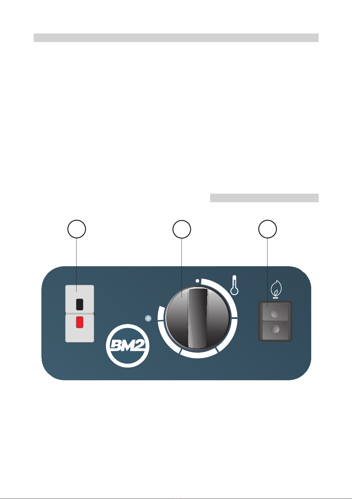
• avviare l’idropulitrice premendo il tasto nero “I” dell’interruttore ma-
gneto-termico (1).
• premere la leva dell’impugnatura automatica e dirigere il getto d’ac-
qua verso la superficie da pulire.
• se si desidera effettuare il lavaggio con acqua calda:
• premere l’interruttore bruciatore (2) nella posizione ;
• ruotare la manopola (3) del termostato sino a raggiungere il valore
di temperatura desiderato.
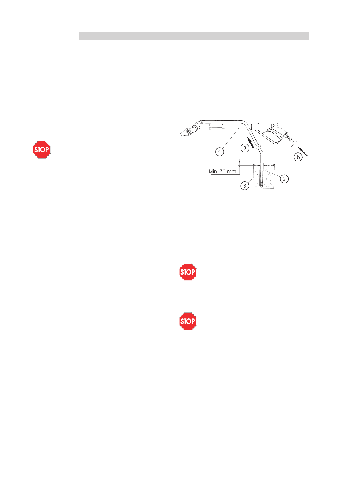
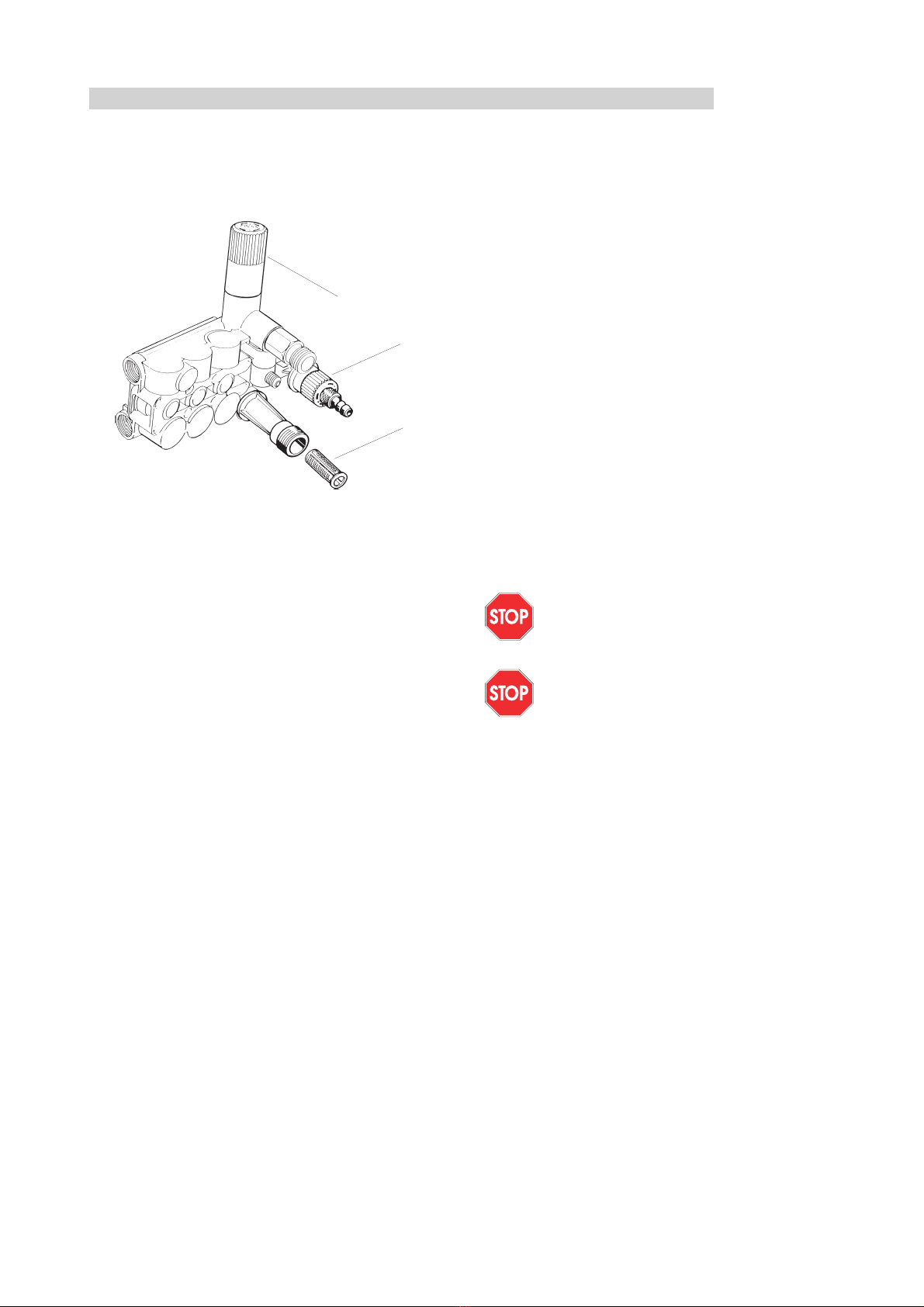
• se si desidera effettuare il lavaggio con iniezione di prodotto deter-
gente si deve ruotare in senso orario la testina portaugello regolabi-
le; la quantità di detergente può essere pre-regolata aprendo o chiu-
dendo il dosatore detergente posto sul circuito idraulico subito do-
po la valvola di sicurezza. Al termine si deve ruotare in senso antio-
rario la testina portaugello regolabile.
3
ITALIANO

ITALIANO
4
INTERRUZIONE DEL LAVAGGIO
Se si rende necessario interrompere il lavaggio per un breve inter-
vallo di tempo é sufficiente rilasciare la leva dell’impugnatura automati-
ca; nei modelli by-pass, si interrompe immediatamente il getto d’acqua
e la pompa A.P. rimane in funzione ricircolando l’acqua.
L’idropulitrice riprende automaticamente il normale funzionamento
premendo la leva dell’impugnatura automatica.
Nei modelli fermo macchina invece, il bruciatore si spegne e la
pompa A.P. rimane in funzione solo per alcuni secondi ricircolando
l’acqua, prima di fermarsi.
L’idropulitrice riprende automaticamente il normale funzionamento
premendo la leva dell’impugnatura automatica: il getto d’acqua riprende
e il bruciatore si riaccende.
Attenzione
Il periodo di sosta, per i modelli by-pass, non deve esse-
re superiore a 5 minuti, trascorsi i quali la testata della
pompa può scaldarsi sino al danneggiamento delle guar-
nizioni di tenuta delle valvole (leggere il paragrafo “In-
convenienti di funzionamento, cause e rimedi”).
ARRESTO DEL FUNZIONAMENTO
Per arrestare il funzionamento dell’idropulitrice, si deve:
• se il bruciatore è ancora acceso
• ruotare in senso antiorario la manopola (3) del termostato sino
a raggiungere la posizione di fondo corsa,
• lasciar funzionare a freddo la macchina per almeno 2 minuti per
raffreddare e risciacquare il circuito idraulico,
• premere l’interruttore bruciatore (2) nella posizione “0”;
• premere il tasto rosso “0” dell’interruttore magneto-termico (1).
PRECAUZIONI CONTRO IL GELO
Durante la stagione invernale l’idropulitrice non deve essere espo-
sta al gelo, se non durante il normale funzionamento; è quindi opportu-
no al termine dell’uso, dopo aver spento il bruciatore e prima di arre-
stare completamente il funzionamento, chiudere il rubinetto dell’alimen-
tazione idraulica e lasciar funzionare l’idropulitrice sino al completo
svuotamento del circuito idraulico.
Nel caso di soste prolungate a bassa temperatura si consiglia di
usare un prodotto antigelo. Dopo aver svuotato il circuito idraulico, si
mette in funzione l’idropulitrice facendo aspirare direttamente il liquido
antigelo attraverso il tubo aspirazione acqua e attraverso il tubo aspira-
zione detergente sino al completo riempimento del circuito idraulico.
DISPOSITIVO PER IDROSABBIATURA (ACCESSORIO DISPONIBILE
PER TUTTI I MODELLI)
Applicando all’idropulitrice il dispositivo per idrosabbiatura é pos-
sibile lavare e pulire superfici ricoperte da ruggine, pitture o incrosta-
zioni tenaci.
Il dispositivo per idrosabbiatura é di facile applicazione (si veda la
figura seguente): é sufficiente sostituire la lancia di lavaggio con la lan-
cia per sabbiatura (1) e inserire il tubo aspirazione sabbia (2) nel reci-
piente (3), avendo cura di utilizzare sabbia asciutta e di qualità adatta
all’uso (sabbia al quarzo o sabbia silicea).
Fig. 1
1. Lancia per sabbiatura
2. Tubo aspirazione sabbia
3. Recipiente
Avviando l’idropulitrice, la sabbia (a) viene aspirata, miscelata al-
l’acqua (b) e proiettata verso la superficie da trattare, liberandola dai re-
sidui e dalle incrostazioni.
MANUTENZIONE
Attenzione
Tutte le operazioni descritte in questo paragrafo devono
essere eseguite solo da personale professionalmente
qualificato.
Per il regolare funzionamento dell’apparecchio è necessario effet-
tuare periodicamente le seguenti operazioni, avendo cura di escludere
la linea elettrica di alimentazione dell’idropulitrice prima di iniziare.
Attenzione
Prima di iniziare l’ operazione si deve:
• Arrestare la macchina secondo le indicazioni del para-
grafo “Arresto”,
• Disinserire l'alimentazione elettrica agendo sull’inter-
ruttore di sezionamento posto sul quadro elettrico di ali-
mentazione
• Chiudere il rubinetto della linea idraulica di alimenta-
zione e svitare il raccordo portagomma del tubo ingresso
acqua.
POMPA AD ALTA PRESSIONE, POMPA A.P.
Il livello di olio nella pompa deve essere periodicamente controllato
utilizzando l’apposita asta di controllo livello; l’olio deve essere sostituito
dopo le prime 50 ore di funzionamento e successivamente ogni 500 ore
di lavoro utilizzando olio SAE 20/30 antischiuma (capacità olio: 0,4 l).

5
FILTRO ACQUA
Il filtro, che è disposto all’inteno del raccordo in plastica all’ingres-
so della pompa A.P., deve essere pulito frequentemente e rimontato
con cura per evitare aspirazione di aria.
Fig. 2
1. Valvola di regolazione della pressione
2. Rubinetto detergente
3. Filtro acqua
BRUCIATORE E FILTRO
Periodicamente si deve pulire l’ugello gasolio e controllare la rego-
lazione e lo stato degli elettrodi: l’ugello gasolio deve essere sostituito
ogni 200 ore e gli elettrodi ogni 500 ore.
POMPA E FILTRO GASOLIO
Periodicamente la pompa gasolio deve essere smontata e ripulita
degli eventuali residui. Il filtro gasolio deve essere sostituito ogni 100
ore di funzionamento.
CAMERA DI COMBUSTIONE
Ogni 200 ore di funzionamento la camera di combustione deve es-
sere completamente smontata e pulita. Dopo aver smontato il coper-
chio superiore ed estratto il boccaglio, si sfila la serpentina e con l’au-
silio di una spazzola metallica e di un aspiratore si elimina la fuliggine e
ogni eventuale residuo della combustione.
DISINCROSTAZIONE
Periodicamente si deve effettuare il lavaggio disincrostante del cir-
cuito idraulico per eliminare i depositi calcarei che tendono a formarsi
ostruendo in particolar modo il passaggio nella serpentina di riscalda-
mento.
Per svolgere tale operazione si deve utilizzare il detergente disin-
crostante prescritto dal costruttore (rivolgersi al Servizio Assistenza
Tecnica per ulteriori chiarimenti). Il lavaggio disincrostante consiste
nel:
• chiudere il rubinetto dell’alimentazione idraulica e versare la dose
consigliata del liquido disincrostante in un recipiente di medie di-
mensioni; nel medesimo recipiente si deve immergere anche il
tubo di aspirazione dell’acqua dopo averlo svitato dal rubinetto di
alimentazione idraulica;
• svitare il tubo A.P. dall’impugnatura automatica della lancia di la-
vaggio e, dopo aver applicato all’estremità libera un filtro in tela
per trattenere le parti calcaree, immergerlo nel recipiente;
• avviare l’idropulitrice (è sufficiente il funzionamento della sola
pompa A.P.) e lasciarla funzionare per almeno 20 minuti;
• al termine della disincrostazione, si toglie il tubo A.P. dal reci-
piente e si rimuove il filtro in tela eliminando le parti trattenute
dal filtro; dopo aver ripristinato il collegamento alla rete idraulica,
si riapre il rubinetto dell’alimentazione idraulica e si avvia l’idro-
pulitrice lasciando fuoriuscire il getto d’acqua dal tubo A.P. sen-
za lancia di lavaggio sino a quando il circuito idraulico sia stato
completamente risciacquato.
Il lavaggio disincrostante deve essere svolto ogni 100 ore di fun-
zionamento se l’acqua è caratterizzata da valori medi di durezza totale
(25 - 30 gradi francesi ), ogni 50 - 60 ore di funzionamento se l’acqua
ha durezza totale maggiore.
TRASPORTO E MOVIMENTAZIONE
TRASPORTO DEL PRODOTTO IMBALLATO
L’imballo è stato progettato per poter essere facilmente movimen-
tato con mezzi meccanici (carrello elevatore, carro ponte, etc.): è suffi-
ciente controllare che i punti di presa siano quelli predisposti sul basa-
mento in legno.
Se necessario, più imballi possono essere sovrapposti: si deve co-
munque rispettare l’indice di sovrapponibilità riportato sull’imballo me-
desimo, avendo cura di allineare i colli ed evitare la formazione di pile
instabili.
MOVIMENTAZIONE
La movimentazione e il trasporto devono essere svolti afferrando
la macchina per la maniglia anteriore e facendola scorrere sulle ruote.
Attenzione
Non tentare mai il sollevamento manuale dell’idropulitri-
ce: il peso eccessivo potrebbe produrre danni fisici rile-
vanti.
Attenzione
Prima di spostare l’apparecchio si deve:
• Arrestare la macchina secondo le indicazioni del para-
grafo”Arresto”,
• Disinserire l’alimentazione elettrica rimuovendo la spi-
na e
• Chiudere il rubinetto dell’alimentazione idraulica e svi-
tare il tubo ingresso acqua.
1
3
2
ITALIANO

ITALIANO
6
INCONVENIENTI DI FUNZIONAMENTO, CAUSE E RIMEDI
INCONVENIENTE DI FUNZIONAMENTO CAUSA RIMEDIO
• Verificare le caratteristiche della
alimentazione elettrica
• Verificare i collegamenti elettrici
• Verificare le caratteristiche della
alimentazione elettrica
• Verificare i collegamenti elettrici
• Controllare che l’ugello acqua
corrisponda a quello dichiarato di serie
• Pulire l’ugello acqua
• Regolare la valvola bypass
• Ugello della lancia intasato • Pulire l’ugello
• Ugello non adatto al tipo di macchina • Sostituire l’ugello
• Valvola bypass non tarata o sporca • Procedere alla pulizia e alla taratura
della valvola
• Anello di tenuta lato corpo pompa
usurato
• Controllare e/o sostituire l’anello di
tenuta
• Alta percentuale di umidità nell’aria • Sostituire l’olio con frequenza doppia
rispetta a quella prescritta
• Guarnizioni usurate • Sostituire le guarnizioni
• Aspirazione d’aria lungo il tubo di
entrata acqua
• Controllare che il tubo di entrata
acqua e il tappo del filtro acqua siano
ben serrati
• Rubinetto detergente aperto e/o
contenitore detergente vuoto
• Chiudere il rubinetto detergente e/o
riempire il contenitore del detergente
• Valvola bypass bloccata • Smontare la valvola e pulirla
• Guarnizioni della pompa consumate • Sostituire le guarnizioni
• Valvole di aspirazione e/o di mandata
della pompa otturate, sporche o usurate
• Controllare le superfici di chiusura
delle valvole e pulirle
• Avviamento della macchina senza aver
scaricato completamente l’aria dal
circuito
• Togliere la lancia di lavaggio e lasciar
funzionare la pompa A.P. per alcuni
secondi
• Cuscinetti usurati • Sostituire i cuscinetti
• L’idropulitrice non si avvia • Alimentazione elettrica interrotta o
insufficiente
• Durante il funzionamento la macchina
si ferma e il pulsante dell’interruttore
magnetotermico (1), si sgancia
• Alimentazione elettrica interrotta o
insufficiente
• Intervento del relè termico a causa di
eccessivo assorbimento di corrente
• Il getto d’acqua è regolare, ma con
valori di pressione molto bassi
• L’olio della pompa A. P. presenta
tracce di acqua
• La pompa funziona con pulsazioni
irregolari, variazioni di pressione e
rumorosità

7
INCONVENIENTI DI FUNZIONAMENTO, CAUSE E RIMEDI
INCONVENIENTE DI FUNZIONAMENTO CAUSA RIMEDIO
• Motore ventilatore MP senza
alimentazione elettrica
• Controllare l’interruttore bruciatore IB
e i collegamenti elettrici
• Motore e/o condensatore difettosi • Controllare il condensatore e il
motore
• Pressione di mandata dell’acqua molto
bassa
• Controllare la voce “Il getto d’acqua è
regolare, ma con valori di pressione
molto bassi”
• Pressostato non funzionante • Sostituire il pressostato
• Termostato non funzionante • Sostituire il termostato
• Gasolio esaurito • Riempire il serbatoio gasolio
• Filtro gasolio intasato • Pulire e/o sostituire il filtro gasolio
• Giunto di accoppiamento
motore/pompa gasolio danneggiato • Sostituire il giunto
• Pompa gasolio usurata • Sostituire la pompa
• Ugello gasolio sporco o rovinato
• Pulire l’ugello con aria compressa o
con gasolio ed eventualmente
sostituirlo
• Scintilla d’accensione debole o
mancante
• Controllare gli elettrodi e/o il
trasformatore d’accensione
• Elettrovalvola gasolio non funzionante • Pulire e/o sostituire l’elettrovalvola
• Elettrodi d’accensione sporchi o mal
regolati • Pulire e regolare gli elettrodi
• Infiltrazioni d’aria nelle tubazioni di
as
p
irazione del
g
asolio
• Controllare il serraggio di tutti i
raccordi
• Guarnizioni usurate • Sostituire le guarnizioni
• Pistone usurato • Sostituire il pistone
• Guarnizione O.R. tappo usurata • Sostituire la guarnizione O.R.
• Perdite di olio tra testata e corpo
p
om
p
a
• Anelli di tenuta lato corpo pompa
usurati • Sostituire gli anelli di tenuta
• La portata di combustibile è
insufficiente
• Pulire l’ugello gasolio e/o il filtro
gasolio
• La pressione del flusso di gasolio è
insufficiente • Tarare la pompa gasolio o sostituirla
• La serpentina di riscaldamento è
intasata da incrostazioni calcaree
• Seguire le istruzioni del paragrafo
“Disincrostazione”
• Il bruciatore si avvia (il ventilatore
funziona), ma non si accende la fiamma
• Perdite di acqua tra testata e corpo
pompa
• Pur regolando il termostato alla
massima temperatura, l’acqua è tiepida
• Il bruciatore non si avvia
(il ventilatore non funziona)
ITALIANO

ENGLISH
DESCRIPTION
SUSETTE water cleaners are suitable for the professional use whe-
re a high temperature and high pressure washing isneeded.
Water is pushed forward by a high pressure pump, A.P pump, th-
rough the hydraulic circuit up to the heating coil heated by a gasoil bur-
ner. It can be equipped with an external detergent tank whose quantity
can be regulated, mixed whith water and delivered with low pressure.
The operator points the water jet at the surface to be cleaned or degrea-
sed operating the lance and pulling the automatic handle lever. If the
automatic hand lelever is realesed, water jet will stop immediately.
In the by-pass models, the pump will recycle water. In the total
stop models, the burner will stop and the pump recycles water for so-
me second before stop.
Attention
The water cleaner main technical features are detailed
on an adhesive nameplate placed on the watercleaner
base plate.
GENERAL ADVICE
• Follow the instructions in this manual carefully
• Do not place inflammable materials near the machine (min. di-
stance 3mt.)
• Use the water cleaner out doors or in a well ventilated place. An
electrics witch board with suitable characteristics should be near
the machine.
• Do not use electrical extensions
• Do not point the water jet at the water cleaner or other electrical
parts
• Do not use dirty or sandy water nor inflammable, chemical or
corrosive products
• Do not point the water jet at people, animals or electrical parts
• Check the machine before use and don't let animals or children
near the machine
• After use make sure the disconnecting switch is off.
INSTALLATION
PACKAGING REMOVAL
To remove packaging used for shipment:
• remove the plastic strap used to fix the machine to the wooden
base
• lift the carton box up
• remove the boards fixed on the wooden base which lock the
wheels and
• push slowly the water cleaner down the base
Attention
Never try to lift the machine manually. Doing so could re-
sult in physical injury.
ELECTRICAL CONNECTIONS
The water cleaner Susette 120 M is equipped to be connected to
single phase power mains, 50 Hz, 230 V.
The other models, that is to say Susette 120T, 150 T, 170 T, are
equipped to fit three-phase power mains, 50 Hz, 400. Models 120T and
150T can be also equipped to fit three-phase power mains, 50 Hz, 230
V (see "Power supply voltage variation").
Attention
The power mains must be earthed and have a magneto-
thermal switch with differential.
The machines with three-phase electrical feeding, have power sup-
ply characteristics detailed on the adhesive label stcked on the motor-
hood: before connecting the power lead, check that they correspond to
those of the fixed electrical plant.
POWER VOLTAGE VARIATION (THREE-PHASE MODELS ONLY)
The water cleaners are standard fitted to be connected to three-
phase power mains, 50 Hz, 400 V. If the electric equipment should be
changed to 230 V or vice-versa to fit other kind of power mains, the fol-
lowing operations must be carried out:
• replace the magneto-thermal switch, setting the thermal relay to
the value indicated in the technical features scheme.
• connect the small bars of the motor terminal board as indicated
in the electrical schemes included in this manual.
• move the jumper on control unit (AP) to 0 - 230V.
• replace the adhesive label with another one showing the selected
voltage.
LANCE PREPARATION
The pakaging contains:
• high pressure hose, AP, already connected to the automatic
handle and to the fixed semi-lance.
• the mobile semi-lance, already prepared with the water nozzle to
beused and only for AR models, the adjustable nozzle head.
After screwing the fixed semi-lance on the mobile one, connect the
AP hose to the water exit connection on the water cleaner,
screwing the rapid connection fitting.
WATER MAINS CONNECTION
Connect a rubber hose with 19 mm. internal section to the water
entrance pipe of the water cleaner by means of the hose coupling al-
ready screwed.
The hose from the water supply shall be fre of incrustation and im-
purities, which may compromise the proper functioning of the cleaner.
For the water cleaner to operate regularly, the feeding pressure
should beat least 1,5-2 bar: lower pressures may cause the AP pump to
suck airin.
GASOIL TANK
The fuel tank must be filled with clean gasoil only, avoiding acci-
dental introduction of water or any other impurity.
INSTRUCTIONS FOR USE
SWITCHING ON AND WASHING
• open the water mains cock.
• switch the water cleaner on pressing the magneto-thermal switch
black key" I " (1).
• pull the automatic handle lever and point the water jet at the sur-
face tobe cleaned.
• If you intend to use hot water:
• press the burner switch (2) to ;
• turn the thermostat knob (3) to reach the desired temperature.
• if you intend to use detergent: rotate clock wise the adjustable-
nozzle head; the detergent quantity can be preset opening or clo-
sing the detergent dispenser placed on the hydraulic circuit after
the security valve. When finished, rotate anticlock wise the adju-
stable nozzle head.
WASHING STOPPAGE
If you want to stop washing for a while, just release the automatic
handle lever.
In the by-pass models the water jet will immediately stop, and the
AP pump recycles water. The water cleaner will automatically restart by
pulling the automatic handle lever: the water jet restarts.
In the total stop models the water jet will immediately stop, the
burner cuts out and the A.P. pump recycles water for some seconds
before stop. The water cleaner will automatically restart by pulling the
automatic handle lever: the water jet and the burner restart.
Attention
Stoppage time for by-pass models must not be longer
than 5 minutes in bypassmodels.After this time the pump
head may heat up and damage the valve seals(cfr."obser-
ved faults, causes and remedies")
8

TURNING OFF
To turn the water cleaner off, you must:
• if the burner is still on:
• rotate anticlock wise the thermostat knob (3) up to the end,
• let the machine operate for at least 2 minutes to cool down and
rinse the hydraulic circuit,
• press the burner switch (2) to "0" position
• press the red key "0" of the magneto-thermal switch (1).
HINTS FOR FREEZING
During winter season the water cleaner must not be kept in the
cold except for normal operation; after use, turn off the burner but ,
before stopping completely the machine, close the water mains cock
and let the water cleaner operate until the water in the hydraulic circuit
is expelled.
In case of long breaks at low temperatures it's advisable to use an
antifreeze product. Empty the hydraulic circuit thens witch on the water
cleaner letting it suck the antifreeze through the water suction pipe and
through the detergent suction pipe to fill up completely the hydraulic
circuit.
WATER SANDBLASTING DEVICE (OPTIONAL FOR EVERY MO-
DEL)
Connecting the water sandblasting device to the water cleaner
could result useful to wash and clean rusty or covered with hard scales
or painting surfaces.
It's easy to connect (see picture below): just replace the washing
lance with the sandblasting one (1) and introduce the sand suction pipe
(2) into the container (3), using dry, quality sand suitable for this use
(quartz sand or siliceous sand).
When the water cleaner is started, the sand (a) is sucked, mixed to
water (b) and addressed to wards the surface to be treated , freeing it
from scales.
Fig.1
1. Water sandblasting lance
2. Sand suction pipe
3. Container
MAINTENANCE
Attention
The following operations must be carried out by qualified
personnel only.
To keep the machine perfectly efficient it's necessary to check it
out periodically. Please disconnect the electrical supply before starting
any operation.
Attention
Before starting to operate:
• stop the machine as instructed before ("Turning off")
• Disconnect the electrical supply turning off the dicon-
necting switch on the electrical switch board
• Close the water mains cock and unscrew the hose cou-
pling of the water entrance pipe.
HIGH PRESSURE PUMP, A.P. PUMP
The oil level in the pump must be checked out periodically by mean
sof the proper dip stick. Oil must be replaced after the first 50 working
hours, after wards every 500 working hours using Antifoam SAE 20/30
oil (oil capacity: 0,4 l).
WATER FILTER
The filter, which is placed into the plastic fitting at the beginning of
A.P. pump, must be frequently cleaned and carefully replaced to avoid
air suction.
Fig.2
1. Pressure adjustment valve
2. Detergent tap
3. Water filter
BURNER AND FILTER
Periodically clean the gasoil nozzle and check setting and condition
of the electrodes : the gasoil nozzle must be replaced every 200 hours
and the electrodes every 500 hours.
GASOIL FILTER AND PUMP
Periodically remove the gasoil pump and clean it. Replace the ga-
soil filter every 100 working hours.
9
1
3
2
ENGLISH

ENGLISH
COMBUSTION CHAMBER
Every 200 working hours, the combustion chamber must be com-
pletely removedand cleaned.
Remove the upper lid, remove the nozzle, take the coil off and eli-
minate the soot and the combustion waste products with a metallic
brush and a vacuum cleaner.
DESCALING
It's advisable to carry over a descaling washing of the hydraulic
circuit periodically to eliminate the scales which might obstruct the
passage in the heating coil.
To carry out this operation, use the descaler recommended by the-
manufacturer (call the Assistence Service for information). Descaling
washing must be carried out as follows:
• close the water mains cock and pour the recommended dose of
descalerin a medium size container; unscrew the water suction pi-
pe from the water mains cock and dip it in the container too;
• unscrew the AP pipe from the automatic handle of the washing lan-
ce and dip it into the container after placing acloth filter to its free
ending to keep scales;
• start the water cleaner (AP pump alone may operate) and let it
perate for about 20 minutes;
• at the end of descaling, take the AP pipe out of the water contai-
ner, remove the cloth filter eliminating the scales. Reconnect to
the water mains, open the water supply cock and start the water
cleaner letting the water jet comes out from the AP pipe with out
washing lance until the hydraulic circuit has been completely rin-
sed.
Descaling washing must be carried out every 100 working hours if
wateris characterized by medium total hardness values (25-30
French degrees), every 50-60 working hours if water presents a
higher total hardness.
TRANSPORTING AND MOVING THE WA-
TER CLEANER
The packaging can be easily moved mechanically (platform
truck,overhead crane etc.). Just check that grip points are those preset
on the wooden base.
Packagings can be laid one on top of the other after reading the in-
structions and warnings placed on the packaging it self. Do not in any
case form unstable piles.
MOVING
To move the water machine use front handles and let it run on it-
swheels.
Attention
Never try to lift the water cleaner manually. Doing so
could result in physical injury.
Attention
Before moving the machine:
•Turn it off as indicated before
• Disconnect electricity by pulling out the plug and
• Close the water supply cock and unscrew the water en
trance pipe.
10

11
OBSERVED FAULTS, POSSIBLE CAUSES AND REMEDIES
OBSERVED FAULT CAUSES REMEDIES
• Check power supply characteristics
• Check electrical connections
• Check power supply characteristics
• Check electrical connections
• Check that the water nozzle corresponds to the
declared stock one
• Clean the water nozzle
• Adjust the bypass valve
• Clogged lance nozzle • Clean the nozzle
• Wrong nozzle • Replace the nozzle
• Bypass valve not calibrated or dirty • Clean and calibrate the valve
• Pump body side sealing ring worn out • Check and/or replace the sealing ring
• High moisture percentace in the air • Replace oil twice in comparison with prescribed
frequency
• Worn out seals • Replace seals
• Air suction in the water entrance pipe • Check that the water entrance pipe and the
water filter tap are tightly closed
• Detergent tap open and/or
em
p
t
y
deter
g
ent tank • Close the tap and/or fill the tank
• Blocked bypass valve • Remove the valve and clean it
• Pump seals worn out • Replace the seals
• Inlet/delivery valves obstructed, dirty or worn
out
• Check closure surfaces of the valves and clean
them
• The machine is started without discharging the
air completely from the circuit
• Disconnect the washing lance and let the AP
pump work for a few seconds
• Worn out bearings • Replace the bearings
• Electrical supply interrupted/insufficient• The water cleaner won't start
• During operation the machine stops and the
magneto-thermal switch (1)switches off
• Electrical supply interrupted/insufficient
• Thermal relay intervention for excessive current
absorption
• The pump works with irregular pulsations,
pressure variations and noise
• AP pump oil shows water traces
• The water jet is regular but its pressure values
are very low
ENGLISH

12
OBSERVED FAULT CAUSES REMEDIES
• MP fan motor with no electrical supply • Check the burner switch IB and electrical
connections
• Faulty motor and/or condenser • Check the condenser and the motor
• Very low water delivery pressure • Check the point "the water jet is regular but its
pressure values are verylow"
• Manostat out of order • Replace the manostat
• Thermostat out of order • Replace the thermostat
• Consumed gasoil • Fill the gasoil tank
• Gasoil filter clogged • Clean and/or replace the gasoil filter
• Motor/gasoil pump coupling damaged • Replace the coupling
• Gasoil pump worn out • Replace the pump
• Gasoil nozzle dirty or spoiled • Clean the nozzle with compressed air or with
gasoil or replace it
• Weak/no ignition spark • Check the electrodes and/or the ignition
transformer
• Gasoil electro-valve out of order • Clean and/or Replace the electro-valve
• Gasoil flow pressure is insufficient • Clean and adjust the electrodes
• Air infiltrations in the gasoil suction pipes • Check the tightening of all nipples
• Worn out seals • Replace seals
• Worn out piston • Replace the piston
• Worn out O.R. tap seal • Replace O.R. seal
• Oil leaks between head and pump body • Pump body side sealing rings worn out • Replace the sealing rings
• Fuel delivery is insufficient • Clean the oil nozzle and/or the gasoil filter
• Gasoil flow pressure is insufficient • Calibrate the gasoil pump or replace it
• The heating coil is obstructed with scales • Follow the instructions of the paragraph
"Descaling"
• Water is warm even if thermostat is set to
maximum temperature
• The burner won't start (the fan doesn't work)
• The burner starts up (the fan is working) but the
flame doesn't light up
• Water leaks between head and pump body
OBSERVED FAULTS, POSSIBLE CAUSES AND REMEDIES
ENGLISH

SCHEMA ELETTRICO - WIRING DIAGRAM SUSETTE 120M
13

SCHEMA ELETTRICO - WIRING DIAGRAM
14
SUSETTE 120T
150T - 170T

15
SCHEMA ELETTRICO - WIRING DIAGRAM SUSETTE 120T - 150T
TO CHANGE THE POWER VOLTAGE SEE PAGE 8
“POWER VOLTAGE VARATION”
PER CAMBIO TENSIONE DI ALIMENTAZIONE VEDI PG. 3
“VARIAZIONE DELLA TENSIONE DI ALIMENTAZIONE”

16
SCHEMA ELETTRICO - WIRING DIAGRAM SUSETTE 120M ts

17
SCHEMA ELETTRICO - WIRING DIAGRAM SUSETTE 120T ts
150T ts - 170T ts

SCHEMA ELETTRICO - WIRING DIAGRAM SUSETTE 120T ts - 150T ts
18
TO CHANGE THE POWER VOLTAGE SEE PAGE 8
“POWER VOLTAGE VARATION”
PER CAMBIO TENSIONE DI ALIMENTAZIONE VEDI PG. 3
“VARIAZIONE DELLA TENSIONE DI ALIMENTAZIONE”

120 M 120 T 150 T 170 T
120 M ts 120 T ts 150 T ts 170 T ts
Pressione acqua - Water pressure [bar] 120 120 150 160
Portata acqua - Water output [l/min] 10 10 11 14
Potenza - Power [HP] 3 3 4 5,5
Velocità - Speed [rpm] 2800 2800 2800 1450
Numero di fasi - Number of phases 1333
Tensione - Voltage [V] 230 230 / 400 230 / 400 400
Frequenza - Frequency [Hz] 50 50 50 50
[A] 16,5 11 / 6,5 11,5 / 8,5 11
[°C] 95 95 95 95
[W] 3000 2650 3500 4500
Delavan GPH 60° B 1,1 1,1 1,1 1,1
1/8" MEG 25035 25035 2504 2505
Serbatoio gasolio - Gasoil tank [l] 12 12 12 12
[dBA] 81 82 82 79
[mm x mm x mm] 630 x 935 x 735 630 x 935 x 735 630 x 935 x 735 630 x 935 x 735
[kg] 90 90 92 94
SUSETTE
Motore - Motor
CARATTERISTICHE TECNICHE
TECHNICAL SPECIFICATIONS
Taratura relé termico 230/400 V - Thermal relay calibration 230/400 V
Temperatura max acqua - Max. water temperature
Alimentazione elettrica
Power supply
Dimensioni, L x P x A - Dimensions, L x W x H
Peso - Weight
Potenza elettrica totale - Total electrical power
Ugello gasolio - Gasoil nozzle
Ugello acqua - Water nozzle
Livello sonoro a 1 m - Noise level at 1 m
This manual suits for next models
7
Table of contents
Languages:
Other BIEMMEDUE Pressure Washer manuals