BIFFI ECU 1000 Manual

ECU 1000 Installation and Maintenance
Copyright by BIFFI ITALIA.
Copyright by BIFFI ITALIA. Copyright by BIFFI ITALIA.
Copyright by BIFFI ITALIA. All right riserved
All right riservedAll right riserved
All right riserved DTDE326-e1 Pag. i
ECU 1000
INSTALLATION
and
MAINTENANCE
MANUAL
DTDE 326
ECU1000 electronic cards
ECU1000 cabinets

ECU 1000 Installation and Maintenance
Copyright by BIFFI ITALIA.
Copyright by BIFFI ITALIA. Copyright by BIFFI ITALIA.
Copyright by BIFFI ITALIA. All right riserved
All right riservedAll right riserved
All right riserved DTDE326-e1 Pag. ii
INDEX
1
INTRODUCTION 1
2
REFERENCE DOCUMENTS 1
3
GENERAL SAFETY INSTRUCTIONS 1
3.1
Manufacturer 1
3.2
Intended Use 1
3.3
Terms and conditions 3
3.4
Manufacturer’s Liability 3
3.5
Applicable Standards and Regulations 3
4
STORAGE 3
5
DEVICE DESCRIPTION 4
5.1
Block diagram 4
5.2
General features 4
5.3
Inputs and Outputs 5
5.3.1
Digital inputs up to 110Vdc 6
5.3.2
Extension connector 6
5.3.3
Service voltages 6
5.4
Bus interface 6
5.5
ECU1000 power supply module 6
5.6
ECU1000 Electronic cards 7
5.7
ECU1000 cabinet block diagram 8
5.8
ECU1000 cabinet 9
5.9
Installation 10
5.9.1
Installation in hazardous area 11
5.10
Checks to be performed before installation 11
5.11
Cables and Electrical Connections 11
5.11.1
Cables connection 11
5.11.2
Earth connection 12
5.11.3
Cables requirements – EMC protection 13
5.11.4
Wire dimension and type 13
5.11.5
Unused entries 13
5.12
Start-up Procedure 13
6
DECOMMISSIONING 15
7
TROUBLE SHOOTING 16
7.1
Local Operator Interface of ECU1000 off 16
7.2
Local Operator Interface of ECU1000 available 16
7.2.1
Trouble-shooting by Local Operator Interface 16
7.2.1.1
Failure, Alarm and Maintenance Request 16
7.2.1.2
I/O check 17
7.2.2
Trouble-shooting by BIFFI-Assistant SW tool 17

ECU 1000 Installation and Maintenance
Copyright by BIFFI ITALIA.
Copyright by BIFFI ITALIA. Copyright by BIFFI ITALIA.
Copyright by BIFFI ITALIA. All right
All right All right
All right reserved
reserved reserved
reserved DTDE326-e1 Pag. iii
8
ECU1000 CABINET CODE 18
9
ROUTINE TEST OF ECU1000 CABINET 18
REV. DATE PREPARED APPROVED NOTES
0 30/07/2013 M. Giuliani A. Affaticati Issue
1 09/06/2014 M. Giuliani A. Battaglia

ECU 1000 Installation and Maintenance
Copyright by BIFFI ITALIA. All right riserved
Copyright by BIFFI ITALIA. All right riservedCopyright by BIFFI ITALIA. All right riserved
Copyright by BIFFI ITALIA. All right riserved DTDE326-e1 Pag. 1
1 Introduction
The documents DTDE326, DTDE327 and DTDE328 are the Installation, Operation and Maintenance manuals of the
ECU1000, Electronic Control Unit for electro-hydraulic actuators.
The DTDE326 “Installation and Maintenance”, provides the instructions for the installation and maintenance of cabinet
with ECU1000. The DTDE327 “Control functions and Local Operator Interface” provides the instructions to use the
Local Operator Interface, the Positioner and the additional functions to control and monitor the actuator. The
DTDE328 “Functions description, Input characterization-Recorder-Graph-Logger-PST-HPU-On/Off control-Optional
local lamps-PWM module” provides detailed instructions relevant to further ECU1000 functions as Input
characterization, Recorder, Graph, Logger, PST, HPU, On/Off control and Optional local lamps. The manuals
DTDE326, DTE327 and DTDE328 provide the instructions relevant to the complete set of ECU1000 functions. Only
functions requested by the application and needed to allow the correct actuator control and operation will be activated in
the factory setting. The warnings reported in this manual consider the risk analysis of the document DTDE331.
2 Reference documents
DTDE 327 “Control functions and Local Operator Interface” of ECU1000
DTDE328 “Functions description”, Input characterization-Recorder-Graph-Logger-PST-HPU-On/Off control-Optional
local lamps-PWM module”
DTDE300 ECU1000 “Product description”
DTDE330 “ECU1000 BIFFI-Assistant User Manual”
DTDE331 ECU1000 “Cabinet data and risk assessment”
Electrical diagram of cabinet with ECU1000 device code 193AR000xxx
Factory test procedure of cabinet with ECU1000 device code 193AR000xxx
Hydraulic diagram and installation and operation manuals of mechanical and hydraulic equipment controlled by the
ECU1000 cabinet 193AR000xxx
3 General Safety Instructions
3.1 Manufacturer
Manufacturer with respect to Machinery Directive 2006/42/EC is BIFFI Italia, as specified on the machinery label.
3.2 Intended Use
The ECU1000 electronic device described in the reference documents is designed to control an electro-hydraulic
actuator for process valves. The main functions are:
•to acquire the feedbacks from sensors of HA (Hydraulic Actuator), HCU (Hydraulic Control Unit), HPU
(Hydraulic Power Unit)
•to acquire the setpoints from control room
•to process the acquired data and send operational commands to HA, HCU, integral HPU
•to monitor the complete system
•to send to control room signals relevant to status and alarms of complete system
•to log events, alarms and failures
BIFFI Italia will not be liable for any possible damage or physical injury resulting from use in other than the designated
applications or by lack of care during installation, operation, adjustment and maintenance of the machine. Such risks lie
entirely with the user. Depending on the specific working conditions, additional precautions may be requested.
Considering that Biffi Italia has no direct control over particular applications, operation or maintenance conditions, it is
the operator’s responsibility to comply with all applicable safety rules. Please inform Biffi Italia urgently if you face
unsafe situations not described in the mentioned IOM’s. It is the sole responsibility of the operator to ensure that the
local health and safety regulations are adhered to.

ECU 1000 Installation and Maintenance
Copyright by BIFFI ITALIA. All right riserved
Copyright by BIFFI ITALIA. All right riservedCopyright by BIFFI ITALIA. All right riserved
Copyright by BIFFI ITALIA. All right riserved DTDE326-e1 Pag. 2
Warning:
•It is assumed that the installation, the setting, the commissioning, the
maintenance and repair works are carried out by qualified personnel and
checked by responsible Specialists.
•The door of cabinet must be kept “closed” by the key (or equivalent tool).
Operating the unit or working on the Electronics with the cabinet door “open”
could cause personal injury and damage the equipment
Warning:
The ECU1000 controls the actuator, it could control the HPU, it could drive
generic electric, mechanic, pneumatic and hydraulic devices. To avoid unwanted
movement of mechanic parts or leakage of pressurized fluids and risk injury of
people and damage of equipment and ambient, any mechanic, electric, hydraulic
and pneumatic device controlled by the ECU1000 device should be placed in safe
condition before executing any installation, commissioning or maintenance
operation (see relevant instruction manuals of actuator, HPU, etc.)
Warning:
The end user shall provide circuit-breakers and fuses in the marshalling cabinet of
control room, to switch off the Mains and any other voltage applied to ECU1000
cabinet. Before opening the door of the ECU1000 cabinet it is mandatory to check
that any voltage (Mains or Control voltage) is off.
Breakers, fuses, differential breakers, in general any disconnecting device
•shall be in accordance with the local national standards and plant rules.
•shall be sized to be in accordance to the power required by the ECU1000
cabinet and the connected electrical loads with a maximum of 10A.
•shall be suitable located and easily reached
•shall be marked as the disconnecting device for the equipment
•shall not interrupt the protective earth conductor
Warning:
Any repair work other than the operations outlines in the mentioned IOM’s will be
strictly reserved to qualified BIFFI ITALIA personnel or to personnel directly
authorised by the Company itself.
Warning:
The electronic parts of the ECU1000 and all the options can be damaged by a
discharge of static electricity. Before you start, touch a grounded metal surface to
discharge any static electricity.
Warning:
If the device is located in hazardous area a ‘’hot permit’’ must be obtained before
opening the explosion proof enclosures. Moreover the area must be cleaned from
explosive mixture since time keeper battery and residual capacitor charge could
generate electrical spark and cause explosion. The installation must be carried out
in accordance to the applicable Ex-d Standards regarding the electrical
installations in hazardous areas and any other applicable national standard and
rule.
ECU1000 devices are designed in accordance with the applicable International Rules and Specifications, but the
following Regulations must be observed in any case:
•the general and safety regulations
•the plant specific regulations and requirements
•the proper use of personal and protective devices (glasses, clothing, gloves, etc)
•the proper use of tools, lifting and transport equipment.

ECU 1000 Installation and Maintenance
Copyright by BIFFI ITALIA. All right riserved
Copyright by BIFFI ITALIA. All right riservedCopyright by BIFFI ITALIA. All right riserved
Copyright by BIFFI ITALIA. All right riserved DTDE326-e1 Pag. 3
3.3 Terms and conditions
Biffi Italia guarantees each single product to be free from defects and to conform to current goods specifications. The
warranty period is one year from the date of installation by the first user, or eighteen months from the date of shipment
to the first user, whichever occurs first. No warranty is given for products which have been subject to improper storage,
improper installation, misuse, or corrosion, or which have been modified or repaired by unauthorised personnel. Repair
work due to improper use will be charged at standard rates.
3.4 Manufacturer’s Liability
Biffi Italia declines all liability in the event of:
•
use of the device in contravention of local safety at work legislation
•
incorrect installation, disregard or incorrect application of the instructions provided on the device nameplate
and in this manual
•
modifications without Biffi’s authorisation
•
work done on the unit by unqualified or unsuitable persons
3.5 Applicable Standards and Regulations
EN ISO 12100-1: Safety of machinery - Basic concepts, general principles for design. Part 1-Basic terminology,
methodology.
EN ISO 12100-1: Safety of machinery - Basic concepts, general principles for design. Part 2-Technical principles and
specification.
EN 60204/1: Electrical equipment of industrial machines. Part 1- General requirements.
2006/42/EC: Machinery directive.
2004/108/EC: EMC Directive
94/9/EC: ATEX Directive (if used in hazardous area)
2006/95/EC: Low Voltage Directive
IEC 60068-2-6, IEC 60068-2-57: Vibration Test
IEC 61010-1 Safety requirements for electrical equipment for measurement, control and laboratory use
4 Storage
Important
:
Not performing the following instructions will invalidate the product guarantee.
All ECU1000 cabinets leave the factory in perfect condition. When mounted together with the actuator they are
guaranteed by the actuator test certificate; in other cases they are guaranteed by an individual certificate. In order to
maintain these characteristics until the ECU1000 is installed on site, proper attention must be observed for preservation
during the storage period.
The standard plastic plugs used to protect the cable entries during the transport are not waterproof; they just prevent the
entry of undesired objects during transport: during the storage it is recommended to replace them with waterproof
version.
In any case storage is recommended in close ambient without excessive humidity.

ECU 1000 Installation and Maintenance
Copyright by BIFFI ITALIA. All right riserved
Copyright by BIFFI ITALIA. All right riservedCopyright by BIFFI ITALIA. All right riserved
Copyright by BIFFI ITALIA. All right riserved DTDE326-e1 Pag. 4
5 Device Description
This paragraph summarizes only the main important functions of cabinet with ECU1000. Detailed description of
functions is available in the manuals DTDE327 and DTDE328.
5.1 Block diagram
The ECU1000 is supplied at 24VDC. A power supply module should be provided in the cabinet to generate the
requested 24 VDC. The optional driver card is requested to drive proportional valves by PWM signals.
5.2 General features
•Control of any BIFFI hydraulic actuator (OLGA-H, OLGAS-H, HLA, HLA-S, single acting spring return or
double acting, modulating and on-off service)
•Standard functions:
1. Positioning of modulating actuator (heavy duty, low drain-heavy duty, stepping)
2. Control of integral HPU with single or dual pump. Automatic switch of electrical pumps
3. Control of on-off actuator
4. Partial Stroke Test
5. Input characterization
6. Failsafe function
7. ESD function
8. Interlock function
9. Stay in position by dedicated SOV
10. Outputs to control Servovalves, Proportional Valves, on-off Solenoid Operated Valves (SOV’s),
contactors of Electrical Motor of hydraulic pumps
11. Inputs to read 4-20mA transmitters and switches
12. Optional module to drive proportional valves by PWM signals
•Hardwired and BUS remote control
•Local control
•Local Operator Interface with graphic OLED display and pushbuttons, visible from -40°C
•User friendly navigation in the menu. English language menu.
•Diagnostic function
•Full local parameterization.
•Access to parameter protected by four levels of password
•Configuration data saved in 3 separated permanent memories
•2 Watch-dog timer working in parallel
•Real Time Clock and battery to maintain date and time
•CRC function to validate communication messages and memory content
•Bluetooth wireless communication
•Temperature, humidity and acceleration sensors of electronic cards
•Electronic NAME PLATE of electronic cards
•Failure, Alarm, Event, Connection loggers, graph and recorder
•BIFFI-Assistant, SW tool for PC for connection to actuator via Bluetooth or RS232
Optional driver
card with PWM
Main power
supply
Base card Control card
Display card
Local
control
I/O’s to control room
HA, HCU, HPU
ECU1000
24Vdc
12Vdc
I/O
I/O’s to
control room
HA, HCU,
HPU
I/O’s to HCU
BUS control
Optional BUS card
Main voltage
Cabinet

ECU 1000 Installation and Maintenance
Copyright by BIFFI ITALIA. All right riserved
Copyright by BIFFI ITALIA. All right riservedCopyright by BIFFI ITALIA. All right riserved
Copyright by BIFFI ITALIA. All right riserved DTDE326-e1 Pag. 5
•Operating temperature of electronics from -40 °C to +75 °C
•Electronics suitable to “On-field” operation inside an IP65 or Ex-d cabinet containing:
oECU1000 electronic cards
oPower supply module
oLine filter, fuses, surge arrester, optional magnetothermal switch
oDIN RAIL terminals for connection with control room, HA, HPU and HCU
oOptional Heater
5.3 Inputs and Outputs
Each input and output is configurable and can be associated either to signals to/from control room and HA, HCU, HPU.
•Analogue inputs
4 x 4-20mA analogue inputs, insulating amplifiers and surge arresters. Max voltage drop at 20mA=9V
1 x 4-20mA analogue input, insulating amplifier and surge arresters. Jumper (J6) to select High/Low impedance mode.
Impedance in High impedance mode >100Kohm. Impedance in Low impedance mode <250ohm.
•Analogue output
1 x 4-20mA analogue output, insulating amplifier and surge arresters. Max resistive load 250 ohm, active or passive
current loop, max voltage 24V.
•Digital inputs
10 x digital inputs, optocoupled, max voltage 30Vdc, surge arresters. Max absorbed current 7mA. Logical_0 < 5V,
Logical_1 >15V
•Digital output
1 x digital outputs, optocoupled, surge arresters, max 24V
•Servovalve / proportional valve control
1 x analogue output configurable by jumpers, insulating amplifier and surge arresters
o+-10V, +-10mA, +-15mA, +-50mA, +-100mA
1 x digital output, optocoupled, surge arrester
oenable control to servovalve / proportional valve or general output
1 x digital input, optocoupled, surge arrester
ofault status of servovalve / proportional valve or general input
The Servovalve/Proportional Valve stage is supplied at 24VDC and is protected by a 4A T fuse in the ECU1000
cabinet.
•Output relays
4 x single side stable, SPDT contact, voltage free, max 30Vdc/230Vac/1A
5 x single side stable, SPST NO contact, voltage free, max 30Vdc/230Vac/1A
2 x single side stable, SPST NO contact, voltage free, max 30Vdc/230Vac/1A (on demand latching relay)
According to user request, to the application and to the electrical diagram, some contact is available to the end user as
remote signalling and the remaining contacts are available to control the electrical components of HA, HCU and HPU.
The set of condition to switch each relay is configurable.
Important:
The contacts of the output relays are available on the connectors CN39, CN40 and
CN41 (see par.5.7, RL0 to RL10). If the voltages through the contacts are different
(e.g. 230Vac and 24Vdc), it is suggested to group the contacts with the same voltage
in the same connector. Each contact should be protected by 1AT fuse, not provided
in the ECU1000 cabinet. If the contacts work as control of an external load, the
fuse should be provided in the cabinet containing the electrical load. If the contacts
work as signalling to control room, the fuse should be installed in the marshalling
cabinets of the control room at customer care. Reinforced insulation is provided
between each group of relays connected to connectors CN39, CN40, CN41; basic
insulation is provided between each relay connected to the same connector; the end
user shall provide the same insulation in the external load.

ECU 1000 Installation and Maintenance
Copyright by BIFFI ITALIA. All right riserved
Copyright by BIFFI ITALIA. All right riservedCopyright by BIFFI ITALIA. All right riserved
Copyright by BIFFI ITALIA. All right riserved DTDE326-e1 Pag. 6
5.3.1 Digital inputs up to 110Vdc
It is necessary to add a resistor in series to each input that works at more than 30Vdc, to limit the input current. The
additional resistors can be mounted by the end user in the marshalling cabinet of the control room or by Biffi in the
ECU1000 cabinet. The following table provides the values of resistors.
Voltage Value Voltage Value
48Vdc 2W-6800 Ohm 110Vdc 2W-22000 Ohm
5.3.2 Extension connector
It allows increasing the number of I/O lines to connect an optional driver card card with 2 PWM channel e 2 analog
inputs or a generic proportional valve with PWM control input
5.3.3 Service voltages
1 x out: 24Vdc/100mA isolated to supply the Position transmitter
1 x out: optional 24Vdc/100mA isolated to supply remote controls
5.4 Bus interface
Upon request the ECU1000 can be provided with Modbus RTU bus.
5.5 ECU1000 power supply module
The following power supply modules can be provided in the ECU1000 cabinet:
•Vin=24 Vdc , Vout=24Vdc/max 10A
•Vin=110Vdc, Vout=24Vdc/max 10A
•Vin=110Vac/50 or 60 Hz, Vout=24Vdc/max 10A
•Vin=230Vac/50 or 60 Hz, Vout=24Vdc/max 10A
The power supply module depends on the type of main supply provided by the end user, and is protected by fuses (or
magnetothermal switch), line filter, surge arresters, and reversed polarity (only in case of DC supply).

ECU 1000 Installation and Maintenance
Copyright by BIFFI ITALIA. All right riserved
Copyright by BIFFI ITALIA. All right riservedCopyright by BIFFI ITALIA. All right riserved
Copyright by BIFFI ITALIA. All right riserved DTDE326-e1 Pag. 7
5.6 ECU1000 Electronic cards
CONTROL CARD
DISPLAY CARD
BASE CARD
Aluminium plate
Insulating spacer

ECU 1000 Installation and Maintenance
Copyright by BIFFI ITALIA. All right riserved
Copyright by BIFFI ITALIA. All right riservedCopyright by BIFFI ITALIA. All right riserved
Copyright by BIFFI ITALIA. All right riserved DTDE326-e1 Pag. 8
5.7 ECU1000 cabinet block diagram
Power supply
Vout 24Vdc
Magnetothermal
switch or fuses
Line filter and
Surge arresters
DIN rail
terminals
Main
Supply
PE
DIN rail terminals
Surge arresters
4A T fuse
Optional
Heater
24V/15W
Fuse
1A T
DIN rail terminals
Fuse
4A T
PE bar
IE bar
Chassis IE
PE
J1
Cables to connectors
CN_xx
Cables to connectors
CN_xx
Remove
J1
to
separate PE and IE
Cables to
control room
Cables to
actuator
Cables to
control room
Cables to
actuator
Optional driver
and bus card
Aluminium plate
Fuses1A T are requested in the
marshalling cabinet of control
room to limit the max current
of output relay contacts
Fuses or breaker are requested in the
marshalling cabinet of control room to
switch the main supply of cab
inet
Mounted on the
cabinet door
ECU1000
cabinet
PE: Protection Earth
IE: Instrumentation Earth
Surge arresters
24Vdc

ECU 1000 Installation and Maintenance
Copyright by BIFFI ITALIA. All right riserved
Copyright by BIFFI ITALIA. All right riservedCopyright by BIFFI ITALIA. All right riserved
Copyright by BIFFI ITALIA. All right riserved DTDE326-e1 Pag. 9
5.8 ECU1000 cabinet
The ECU1000 cabinet is suitable to be used outdoor. The cabinet is provided with glass windows to allow viewing the display and 3 pushbuttons to move in menu of ECU1000
or for local command.
Two types of cabinet are available:
•Cabinet AISI 316, IP65 to be used in standard environment. The cabinet door needs a tool to be open. (type CP456025, manufacturer MP Gamma, or equivalent)
•Cabinet Ex-d IIB T5 to be used in hazardous area. The cabinet door needs an appropriate key to be open. (type EJB 51, manufacturer Nuova ASP, or equivalent)
Different types of cabinets can be provided on request.
Warning:
•
The door of cabinet must be kept always closed by key (or tool), to avoid damage of
Electronics due to wet or pollution or personal injury of people. The key to open the
door (or the alternative tool) must be kept by authorized and qualified personnel
•
The cabinet must be connected to “earth”
Cabinet for standard outdoor
environment
Cabinet for hazardous
environment
Cable entry

ECU 1000 Installation and Maintenance
Copyright by BIFFI ITALIA. All right riserved
Copyright by BIFFI ITALIA. All right riservedCopyright by BIFFI ITALIA. All right riserved
Copyright by BIFFI ITALIA. All right riserved DTDE326-e1 Pag. 10
5.9 Installation
The standard ECU1000 is suitable to work in the temperature range -40°C +75°C. Special version can be done in case
of different temperature range.
The ECU1000 cabinet can be supplied as part of the actuator or separately. If ordered as part of an actuator, the factory
mounts the ECU1000 cabinet together with the actuator, makes the connections (pneumatic, hydraulic and electrical) to
the actuator, sets up and calibrates the instrument. In both cases the mounting bracket shall withstand a force of four
times the weight of the ECU1000 cabinet. The following general instructions should be observed.
Important
:
Check that the working temperature range is correct. If the temperature is higher
than the rated values it needs to add a sunshine shield to the ECU1000 cabinet
Warning:
The ECU1000 cabinet is not provided with specific means for lifting and
transporting. Manually move the cabinet according to the effective rules of health
and safety of the installation country.
Warning:
It is assumed that the installation, the setting, the commissioning, the maintenance
and repair works are carried out by qualified personnel and checked by
responsible Specialists.
Warning:
Avoid personal injury or property damage due to handling of mechanical parts.
Before proceeding with any installation operation, the following precautions
should be used
•
Always wear protective clothing, gloves, and protection glasses to prevent
personal injury.
•
If installation is in hazardous area, personal injury or property damage
may result from fire or explosion. Preventive measures may include:
remote venting of the unit, re-evaluating the hazardous area classification,
ensuring adequate ventilation, and the removal of any ignition sources.
Require hot permit before any operation.
•
Check with process or safety engineer for any additional measures that
must be taken to protect against process media.
Important
:
If the installation is in hazardous area, it must be carried out in accordance to the
applicable standards IEC/EN 60079-14 and IEC/EN 60079-17 regarding the
electrical installations in Hazardous Areas (other than mines) classified as Zones 1,
2 (gas) and Zones 21, 22 (dust) following IEC/EN 60079-10-1 and IEC/EN 60079-
10-2 and any other applicable national standards and rules.

ECU 1000 Installation and Maintenance
Copyright by BIFFI ITALIA. All right riserved
Copyright by BIFFI ITALIA. All right riservedCopyright by BIFFI ITALIA. All right riserved
Copyright by BIFFI ITALIA. All right riserved DTDE326-e1 Pag. 11
5.9.1 Installation in hazardous area
Special attention should be paid to the following:
•
before any assembly operation the joint surfaces must be greased.
•
the cable glands must have a protection degree at minimum IP66/68 (EN/IEC 60529).
•
periodically verify the quantity of dust deposited on the enclosure and clean it in the case the quantity
becoming more than 5 mm.
5.10 Checks to be performed before installation
W
arning:
Before the installation it is mandatory to check if the nameplate associated to the
extension for additional entry specifies the appropriate degree of protection and
ambient temperature limits as requested by the Rules applicable to the
plant/location where units are installed.
1) The electrical supply cables must be suitable for the power rating
2) Gather the necessary tools for the assembly and setting of the ECU1000 controls;
3) Verify that the fixing elements (screws, nuts etc.) used for fastening the ECU1000 cabinet can sustain at least four
times the weight of the ECU1000
4) If a long storage period has occurred, before installing the ECU1000:
•
Check the installation of the plugs or cable glands on the cable entries.
•
Check whether the enclosure covers of the ECU1000 cabinet are cracked or broken.
5.11 Cables and Electrical Connections
5.11.1 Cables connection
The sealing of cables and/or conduit entries must be carried out in accordance with National Standards or the
Regulatory Authorities. Method of sealing and cable glands must be approved and separately certified for use in
hazardous areas.
Warning:
The end user shall provide circuit-breakers and fuses in the marshalling cabinet of
control room, to switch off the Mains and any other voltage applied to ECU1000
cabinet. Before opening the door of the ECU1000 cabinet it is mandatory to check
that any voltage (Mains or Control voltage) is off.
Breakers, fuses, differential breakers, in general any disconnecting device
•shall be in accordance with the local national standards and plant rules.
•shall be sized to be in accordance to the power required by the ECU1000
cabinet and the connected electrical loads with a maximum of 10A.
•shall be suitable located and easily reached
•shall be marked as the disconnecting device for the equipment
•shall not interrupt the protective earth conductor
Important
:
To prevent any water infiltration through the line cable conduits, be sure the cable
glands have the minimum degree of protection required by the plant. The cable
glands shall be selected in accordance to the cables section
If rigid conduits make the connection, place a flexible pipe connection between the
conduit and the terminal board.

ECU 1000 Installation and Maintenance
Copyright by BIFFI ITALIA. All right riserved
Copyright by BIFFI ITALIA. All right riservedCopyright by BIFFI ITALIA. All right riserved
Copyright by BIFFI ITALIA. All right riserved DTDE326-e1 Pag. 12
To guarantee weatherproof and explosion-proof fit, screw the cable glands tightly (at least 5 turns) and block them with
a thread sealant. The use of a thread sealant is necessary in case of explosion-proof capability.
If some parts of the cable glands have been removed during work on the cable entries put them back into place now to
avoid losing the dismantled parts.
Important
:
The cables MUST be selected considering as maximum working temperature of
cables the maximum working temperature of ECU1000 device.
Cables should be connected to DIN RAIL terminals provided inside the ECU1000 cabinet.
Important
:
The avoid malfunction and electromagnetic interferences due to cables coupling, it
is recommended to use separated cables for power and signals and if it is possible
also separated conduits. Use of shielded cables for analogue or data signals is
requested.
5.11.2 Earth connection
The ECU1000 cabinet must be connected to EARTH trough the External EARTH stud. The wire section shall be at
least equal to the section of power supply wires.
For the earth connection of the cables dedicated DIN RAIL terminals or EARTH bar are provided.
The chassis is connected to PE (Protection Earth). Power supply module, line filter and surge arresters are connected to
PE. The electronics of ECU1000 and shield of cable for signals are connected to IE (Instrumentation Earth). PE and IE
are isolated. According to plant requirement the end user should use case A or B. The ECU1000 cabinet is supplied
according to case A.
If the end user uses the case Bthe jumper J1 should be removed
PE bar
I
E bar
Chassis
earth stud
Surge arresters, line filter,
power supply module
ECU1000 electronic
boards
PE cable IE cable
PE
IE
ECU1000 cabinet
PE bar
I
E bar
Chassis
earth stud
Surge arresters, line filter,
power supply module
ECU1000 electronic
boards
PE cable
PE
IE
ECU1000 cabinet
J1
Case A
Case B

ECU 1000 Installation and Maintenance
Copyright by BIFFI ITALIA. All right riserved
Copyright by BIFFI ITALIA. All right riservedCopyright by BIFFI ITALIA. All right riserved
Copyright by BIFFI ITALIA. All right riserved DTDE326-e1 Pag. 13
5.11.3 Cables requirements – EMC protection
The table below resumes the specifications of cables for connecting the ECU1000 cabinet.
CONNECTION TYPE CABLES REQUIREMENT
External Power Supply Not shielded
Relay output Multicore, not shielded
Digital Input Multicore, not shielded
Digital Output Multicore, not shielded
Analogue Output Pair, Shielded
Analogue Input Pair, Shielded
5.11.4 Wire dimension and type
Before making any connection to ECU1000 cabinet, checks the electrical parameters present (voltage and current
limits) on the nameplate and in this manual. The connections are available on DIN RAIL TERMINALS.
Max dimension of the wires: 2.5 mm
2
for the standard DIN Rail Terminals.
The dimension and type of the wires must respect the current regulations of the installation country.
5.11.5 Unused entries
Warning:
Replace the plastic plugs with new plugs that guarantee the protection IP degree
required.
If the cabinet is in hazardous area use only certified explosion-proof plugs and
block with a thread sealant to guarantee the tightening. Not performing the above
prescription will invalidate the safety protection in case of presence of hazardous
atmospheres.
5.12 Start-up Procedure
In this section is described a step-by-step procedure to start-up the ECU1000.
All the points must be performed in the order they appears.
Warning:
If the device is located in hazardous area a ‘’hot permit’’ must be obtained before
opening the explosion proof enclosures. Moreover the area must be cleaned from
explosive mixture since time keeper battery and residual capacitor charge could
generate electrical spark and cause explosion.
Warning:
Electrical start-
up should be done when the mechanical setting of the actuator
which is connected to ECU1000 is completed. Refers to instruction manuals of
Hydraulic Actuator, Hydraulic Power Unit, Hydraulic Control Unit.
Warning:
Check that the breaker of the main electrical power in the marshalling cabinet of
control room is off
Check that any control voltage applied to cabinet is off
•Check that the cables coming from control room and actuator are connected to the cabinet terminals according
to electrical diagram. Check that the screws of terminals are correctly tighten
•Check that earth connections are reliable and according to the instructions in the previous paragraphs
•Switch on the main switch inside the ECU1000 cabinet
•Close the door of the ECU1000 cabinet
Note: “Shielded” must be considered as a
more strict condition than “Armoured”.
It is possible to use a shielded cable instead
of a required armoured cable but it is not
possible to use an armoured cable instead of
a required shielded cable.

ECU 1000 Installation and Maintenance
Copyright by BIFFI ITALIA. All right riserved
Copyright by BIFFI ITALIA. All right riservedCopyright by BIFFI ITALIA. All right riserved
Copyright by BIFFI ITALIA. All right riserved DTDE326-e1 Pag. 14
•Check that the actuator is in safe position and no mechanical damage or undesired movement of actuator can
occur. Check that no leakage or dangerous pressure (oil or air) is present in the mechanics and hydraulic
controlled by the ECU1000. Check that hydraulic piping is correctly connected.
•Switch on the breaker of the main electrical power in the marshalling cabinet of control room is off. In general
the ECU1000 is supplied already with the configuration requested by the application. No special configuration
operations are required except the setting of travel limits and tuning of positioner function.
.
•Check the Failure and Alarm. Remove the conditions that cause Failure and Alarm. Refer to manuals DTDE
327 and DTDE328 to see the Failure and Alarm description and conditions.
•Apply the control signals to the ECU1000 cabinet. If the actuator is for modulating service, it starts in
AUTOMATIC mode. Apply a control signal (4-20mA) that keeps the actuator in safe position (closed or open)
•When hydraulic pressure is correct set the actuator travel limits (see DTDE 327 and DTDE328)
•Switch to local control mode and move the actuator by pushbuttons the Up/Open and Down/Close.
•Check that output and input signals to control room and actuator are correct
•Tune the actuator response by means of the Local Operator Interface facilities
•Check the variables as follows:
oFrom HOME VIEW
oPress Up/Open to wake up the display
oPress Up/Open to scroll the list of variables
oPress Enter and see the value
POSITION%: it shows the % of opening of the valve. Check that the value is according to
real valve position
POSITION DEMAND%: if the positioning function is on, this variable shows the valve
requested position.
POSITION ERROR%: if the positioning function is on, this variable shows the difference
between POSITION DEMAND% and POSITION%. It is used to calculate the output signal
(by the parameters GAIN K1 and K2), visible in AO1 OUT %
IN-POS DEMAND%: if the positioning function is on, this variable shows the input signal
of the valve requested position. The values of IN-POS DEMAND% and POSITION
DEMAND% are equals if the Input Characterization function is off
TEMPERATURE °C: it shows the temperature inside the ECU1000 cabinet
HUMIDITY %: it shows the humidity inside the ECU1000 cabinet
ACCELERATION-g: it shows the acceleration level
AO1 OUT %: if the positioning function is on and the hydraulic valve is analogue, this
variable shows the output control signal %
OIL PRESSURE bar: if the actuator is provided with integral HPU controlled by the
ECU1000, this variable shows the HPU oil pressure
NEXT PST: if PST function is on, this variable shows the date of the next PST cycle
PUMPS SWITCH: if the actuator is provided with integral HPU, dual pump, controlled by
the ECU1000, this variable shows the time before the next pump switch
•Return to HOME VIEW
•
Check the Local Operator interface of the ECU1000. The manuals
DTDE 327 and DTDE328 contain the instructions to use the
Local Operator Interface and detailed description of each
ECU1000 function
•

ECU 1000 Installation and Maintenance
Copyright by BIFFI ITALIA. All right riserved
Copyright by BIFFI ITALIA. All right riservedCopyright by BIFFI ITALIA. All right riserved
Copyright by BIFFI ITALIA. All right riserved DTDE326-e1 Pag. 15
•
6 DECOMMISSIONING
Disposal and recycling
At the end of the life the ECU1000 cabinet must be disassembled.
Warning:
Do not dump non-biodegradable products, lubricants and non-ferrous (rubber,
PVC, resins, etc.) into the environment. Dispose of all such materials as indicated
in the following table:
Subject Hazardous Recyclable Disposal
Electrical and electronic equipment Yes Yes Use specialist recyclers.
Glass No Yes Use specialist recyclers.
Metals No Yes Use licensed recyclers.
Plastics No Yes Use specialist recyclers.
Rubber (seals and o-rings) Yes No May require special treatment before disposal,
use specialist waste disposal companies
Battery Yes No May require special treatment before disposal,
use specialist waste disposal companies.
Warning:
Do not re-use parts or components which appear to be in good condition after they
have been checked or replaced by qualified personnel and declared unsuitable for
use.
Important
:
In all cases check local authority regulation before disposal

ECU 1000 Installation and Maintenance
Copyright by BIFFI ITALIA. All right riserved
Copyright by BIFFI ITALIA. All right riservedCopyright by BIFFI ITALIA. All right riserved
Copyright by BIFFI ITALIA. All right riserved DTDE326-e1 Pag. 16
7 TROUBLE SHOOTING
7.1 Local Operator Interface of ECU1000 off
Warning:
•Switch off the main power from ECU1000 cabinet by the breaker in the
marshalling cabinet of control room
•Switch off any control voltage from ECU1000 cabinet
Warning:
If the device is located in hazardous area a ‘’hot permit’’ must be obtained before
opening the explosion proof enclosures. Moreover the area must be cleaned from
explosive mixture since time keeper battery and residual capacitor charge could
generate electrical spark and cause explosion.
Open the ECU1000 cabinet door.
With reference to the dedicated electrical diagram of the ECU1000 cabinet 193AR000xxx
•Perform the visual inspection of electronics, cables and terminals. No component should be damaged, no wires
should be disconnected from terminal and the screws of terminals should be well tightened.
•Check the fuses and the main switch of the ECU1000 cabinet
•Check that the surge arresters are not damaged, by a multimeter measure the continuity between the input and
output terminals
•If none of the above test solve the problem it needs to check the power supply module and then the ECU1000
cards
7.2 Local Operator Interface of ECU1000 available
7.2.1 Trouble-shooting by Local Operator Interface
The manuals DTDE327 and DTDE328 provide detailed instructions on the Local Operator Interface of ECU1000 and
on the Actuator malfunctions. Here below is described only the procedure to see the list of alarm and failure.
7.2.1.1 Failure, Alarm and Maintenance Request
See the display in the HOME VIEW.
•If it signals Failure
oPress Up/Open to wake up the display
oPress Up/Open until the display shows Failure
oPress Enter
oPress Up/Open and Down/Close to scroll the list of Failure
oSee the manual DTDE327, Actuator Malfunction tables to find the description and the reset condition
•If it signals Alarm
oPress Up/Open to wake up the display
oPress Up/Open until the display shows Alarm
oPress Enter
oPress Up/Open and Down/Close to scroll the list of Alarms
oSee the manual DTDE327, Actuator Malfunction tables to find the description and the reset condition
•If it signals Maintenance Request
oSee the manual DTDE327, Actuator Malfunction tables to find the description and the reset condition
oPress Up/Open to wake up the display
oEnter in the menu of the Local Operator Interface
oCheck the Current Date and the Next Maintenance Date
oIf necessary enter new dates

ECU 1000 Installation and Maintenance
Copyright by BIFFI ITALIA. All right riserved
Copyright by BIFFI ITALIA. All right riservedCopyright by BIFFI ITALIA. All right riserved
Copyright by BIFFI ITALIA. All right riserved DTDE326-e1 Pag. 17
7.2.1.2 I/O check
•From HOME VIEW
oPress Up/Open to wake up the display
oPress Up/Open until the display shows Out Relay
oPress Enter
oCheck that each output contact is according to the required application (see electrical and mechanical
diagrams). If an output is in wrong state check the condition associated to relay in the parameter table
oReturn to HOME VIEW
•From HOME VIEW
oPress Up/Open to wake up the display
oPress Up/Open until the display shows Digital Inputs
oPress Enter
oCheck that each digital input is according to the required application and change status when the
connected hardware input changes (see electrical and mechanical diagrams). If an input does not
change check the hardware connected to the input
oReturn to HOME VIEW
•From HOME VIEW
oPress Up/Open to wake up the display
oPress Up/Open until the display shows Analog Inputs
oPress Enter
oCheck that each analog input is according to the required application and changes when the connected
hardware 4-20mA changes. The value of each input is shown in bits, from 0 to 4096 (see electrical
and mechanical diagrams). If an input does not change check the hardware connected to the input
oReturn to HOME VIEW
7.2.2 Trouble-shooting by BIFFI-Assistant SW tool
The manuals DTDE330, DTDE327 and DTDE328 provide detailed instructions on the BIFFI-Assistant SW tool of
ECU1000.
Here below is described only the procedure to see the list of alarm and failure.
•Connect BIFFI-Assistant to actuator
•Select DEVICE COMMANDS
•Select LOG and GRAPH
•Select LOGGER
•Select FAILURE and see the list of failure
•Select ALARM and see the list of alarms
See the manual DTDE327, Actuator Malfunction
tables to find the description and the reset condition.
Remove Failures and Alarms.
Table of contents
Other BIFFI Controllers manuals
BIFFI
BIFFI HLA Series User manual
BIFFI
BIFFI GIG User manual

BIFFI
BIFFI ALGAS-MHP User manual

BIFFI
BIFFI RPS User manual
BIFFI
BIFFI F01-2000 Parts list manual
BIFFI
BIFFI RPS Series User manual
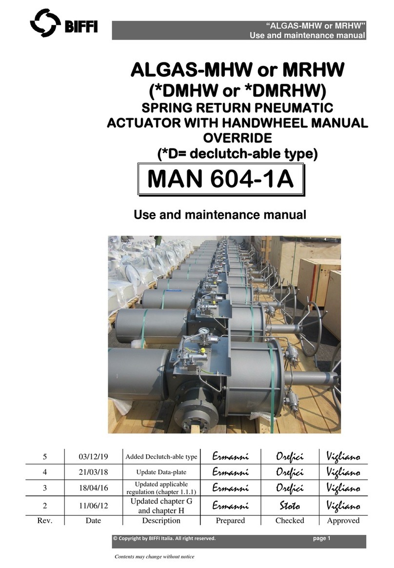
BIFFI
BIFFI ALGAS-MHW User manual
BIFFI
BIFFI PLA User manual
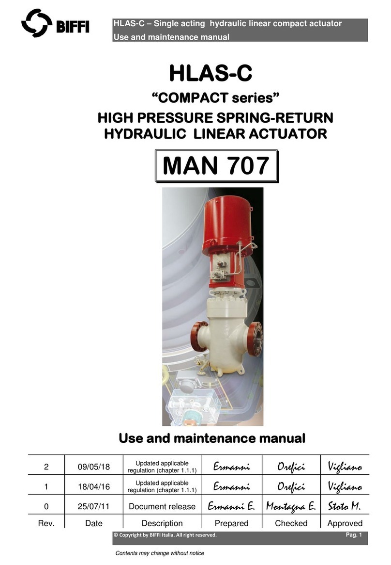
BIFFI
BIFFI COMPACT Series User manual
BIFFI
BIFFI OLGA Series User manual
BIFFI
BIFFI OLGA-H User manual
BIFFI
BIFFI ICON3000 Series User manual

BIFFI
BIFFI OLGA-H User manual
BIFFI
BIFFI ALGAS-QA EAC User manual
BIFFI
BIFFI FCB Series User manual
BIFFI
BIFFI HLRA User manual

BIFFI
BIFFI RP14 User manual
BIFFI
BIFFI ALGA Series User manual
BIFFI
BIFFI HLAS User manual

BIFFI
BIFFI HLAS User manual
