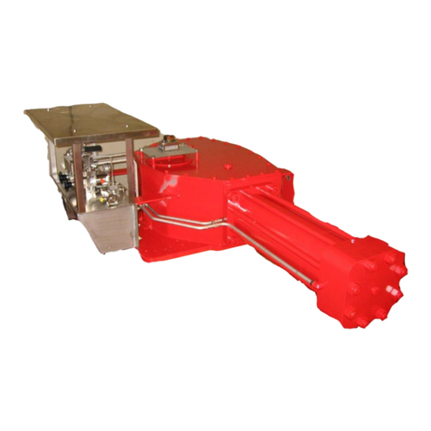
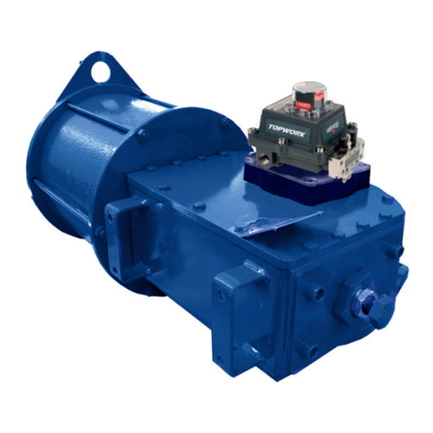
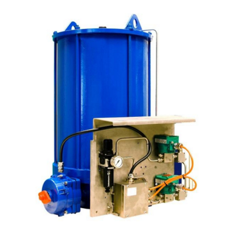
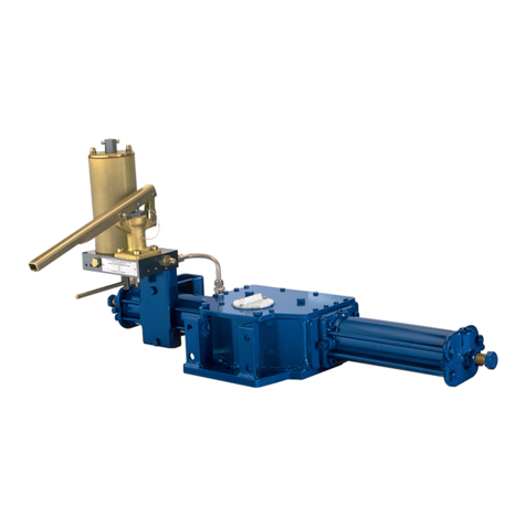
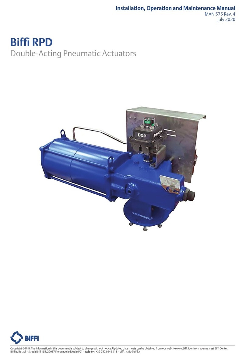
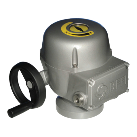
BIFFI F01-2000 User manual

Copyright © Biffi. The information in this document is subject to change without notice. Updated data sheets can be obtained from our website www.biffi.it or from your nearest Biffi Center:
Biffi Italia s.r.l. - Strada Biffi 165, 29017 Fiorenzuola d'Arda (PC) – Italy PH: +39 0523 944 411 – [email protected]
Bif F01-2000
Electric Actuator
Installation, Operation and Maintenance Manual
VCIOM-01249-EN Rev. 0
September 2021
GENERAL INSTRUCTIONS FOR INSTALLATION
OPERATION AND CONFIGURATION
MAINTENANCE AND TROUBLESHOOTING
SPARE PARTS AND DRAWINGS

Revision Details
September 2021
Installation, Operation and Maintenance Manual
VCIOM-01249-EN Rev. 0
Revision Details
Rev. Date Description Prepared Checked Approved
0 September 2021 General update (Migration to new template)
Revision Details

i
Table of Contents
September 2021
Installation, Operation and Maintenance Manual
VCIOM-01249-EN Rev. 0
Table of Contents
Table of Contents
Section 1: General Safety Instructions
1.1 Range of Application..................................................................................... 1
1.2 Safety Instructions for Installation in Hazardous Area .................................... 1
1.2.1 Marking.............................................................................................. 2
1.3 Applicable Standards and Regulations........................................................... 2
1.4 Terms and Conditions ................................................................................... 3
1.5 Identication of the Main Parts...................................................................... 3
Section 2: Storage and Pre-Installation
2.1 Tests to be Carried Out When the Actuator is Received ................................. 4
2.2 Storage Procedure ........................................................................................ 4
2.2.1 General .............................................................................................. 5
2.2.2 Storage for a Brief Period (Less Than One Year) ................................... 5
2.2.3 Long Period Storage (More Than One Year) ........................................ 5
2.3 Checks to be Performed Before Installation................................................... 7
Section 3: Installation
3.1 Working Condition........................................................................................ 8
3.2 Coupling Block: Disassembly from the Actuator ............................................ 8
3.3 Manual Operation ....................................................................................... 10
3.4 Mounting the Actuator onto the Valve ........................................................ 11
3.5 Electrical Connections................................................................................. 12
3.5.1 Identication of Entries..................................................................... 12
3.5.2 Plants Requirements......................................................................... 13
3.6 Removing the Electrical Enclosures’ Covers ................................................. 13
3.6.1 Terminal Board Enclosure ................................................................. 13
3.7 Cable Entries ............................................................................................... 14
3.8 Terminal Board ........................................................................................... 15
3.9 Instructions for the Explosionproof Enclosures ............................................ 18
3.10 Installation in Environment with Explosive Dusts ......................................... 19
Section 4: Lubrication
4.1 Lubrication Inspection................................................................................. 20

ii
Table of Contents
September 2021
Installation, Operation and Maintenance Manual
VCIOM-01249-EN Rev. 0
Table of Contents
Section 5: Operating the F01-2000
5.1 Operation by Handwheel ............................................................................ 21
5.2 Setting of Mechanical Stops ........................................................................ 22
5.3 Electrical Operation .................................................................................... 24
5.4 Local Control............................................................................................... 24
5.5 Local Indication........................................................................................... 25
5.6 Remote Control........................................................................................... 26
5.6.1 Remote Commands.......................................................................... 26
5.7 Lock of the 3-Position Selector .................................................................... 26
5.7.1 Output Contacts .............................................................................. 27
5.7.2 ESD Operation.................................................................................. 28
5.7.3 Interlock Inputs ................................................................................ 30
5.8 Operating the F01-2000 for the First Time .................................................. 30
5.9 Optional Modules........................................................................................ 32
5.9.1 Fieldbus Interface for Remote Control via Fieldbus............................ 32
5.9.2 Ain/Aout Card .................................................................................. 33
5.10 Base Card of the F01-2000 V4 ..................................................................... 35
Section 6: Local Controls
6.1 Description of the Local Operator Interface ................................................. 38
6.2 Conguration Options ................................................................................ 43
6.3 Entering the View Mode.............................................................................. 45
6.4 Entering the Set-up Mode ........................................................................... 46
6.5 Exit from View and Set-Up Mode ................................................................. 46
Section 7: Set-Up Menu
Set-Up Menu..........................................................................................................48
Section 8: View Menu
View Menu............................................................................................................50
Section 9: Set-Up Routines
9.1 Actuator Set-Up .......................................................................................... 52
9.1.1 Set Stroke Limits............................................................................... 52
9.1.2 Torque Set-Up .................................................................................. 54
9.1.3 ESD Control...................................................................................... 54
9.1.4 Remote Controls .............................................................................. 56
9.1.5 Local Controls................................................................................... 56
9.1.6 Output Relays .................................................................................. 57
9.1.7 Positioner......................................................................................... 61
9.1.8 Fail-safe............................................................................................ 64
9.1.9 Out 4 - 20 mA................................................................................... 65
9.1.10 Interlock........................................................................................... 66
9.1.11 2-Speed timer .................................................................................. 66
9.1.12 BUS (or FDI Control) ......................................................................... 68
9.1.13 Miscellaneous................................................................................... 68

iii
Table of Contents
September 2021
Installation, Operation and Maintenance Manual
VCIOM-01249-EN Rev. 0
Table of Contents
9.2 Valve Data................................................................................................... 72
9.2.1 Sample Conguration Procedure...................................................... 73
9.3 Maintenance ............................................................................................... 73
9.3.1 Set Password .................................................................................... 74
9.3.2 Clear Alarm Log ............................................................................... 74
9.3.3 Set Torque Reference........................................................................ 74
9.3.4 Set Curve Reference ......................................................................... 75
9.3.5 Clear Recent Data Log....................................................................... 75
9.3.6 Set Maintenance Date ...................................................................... 76
9.3.7 Set Data Logger................................................................................ 77
9.4 Example of Set-Up Routine.......................................................................... 78
9.4.1 Torque Set-up................................................................................... 78
Section 10: View Routines
10.1 Actuator Set-Up .......................................................................................... 79
10.2 Nameplate .................................................................................................. 80
10.3 Valve Data................................................................................................... 81
10.4 Maintenance ............................................................................................... 81
10.4.1 Alarm Log......................................................................................... 81
10.4.2 Torque Prole................................................................................... 82
10.4.3 Torque Curve.................................................................................... 83
10.4.4 Operation Log .................................................................................. 84
10.4.5 Maintenance Date ............................................................................ 87
10.4.6 Data Logger...................................................................................... 87
10.5 Example of View Routine............................................................................. 91
10.5.1 View Torque Set-Up.......................................................................... 91
Section 11: Maintenance
11.1 Standard Maintenance ................................................................................ 92
11.2 Special Maintenance ................................................................................... 93
11.3 Lithium Battery Change .............................................................................. 94
Section 12: Troubleshooting
12.1 The Electronics Do Not Switch on When Powered ....................................... 98
12.2 DC Output Voltage Not Available at the Terminals....................................... 99
12.3 The Actuator Does Not Work from Remote Controls ................................... 99
12.4 The Motor Is Very Hot and Does Not Start ................................................. 100
12.5 The Motor Runs but the Actuator Does Not Move the Valve ...................... 100
12.6 The Valve Does Not Seat Correctly ............................................................ 100
12.7 Excessive Torque for Valve Operation ........................................................ 100
12.8 The Actuator Does Not Stop in Fully Open or Fully Closed Position............. 101
12.9 The Numeric Position Display Indicates “E01” ........................................... 101
12.10 Diagnostic Messages................................................................................. 101
Section 13: Parts List and Drawings
13.1 Introduction.............................................................................................. 105

Notes
September 2021
Installation, Operation and Maintenance Manual
VCIOM-01249-EN Rev. 0
This page is intentionally left blank

September 2021
Installation, Operation and Maintenance Manual
VCIOM-01249-EN Rev. 0
General Safety Instructions 1
Section 1: General Safety Instructions
1.1 Range of Application
F01-2000 electric actuators covered in this Installation, Operation and Maintenance
Manual are designed for the operation of industrial valves used in heavy industrial,
chemical and petrochemical plants. Bif will not be liable for any possible damage resulting
from use in other than the designated applications. Such risk lies entirely with the user.
The noise emitted by the electric actuator in normal working conditions is less than
66 dB (A) with peak value 115 dB (C). Standard reference ISO 11202 (1st ed., 1995-12-15).

! WARNING
It is assumed that the installation, setting, commissioning, maintenance and repair works
are carried out by qualied personnel and checked by responsible specialists.
The electric actuators are designed in accordance with the applicable international rules
and specications but the following regulations must be observed in any case:
• The general installation and safety regulations.
• The plant specic regulations and requirements.
• The proper use of personal protective devices (glasses, clothing, gloves).
• The proper use of tools, lifting and transport equipment.
1.2 Safety Instructions for Installation in
Hazardous Area
! WARNING
In case the electric actuator must be installed in a HAZARDOUS AREA, as dened by the
local rules, it is mandatory to check if the nameplate of the electric actuator species the
appropriate degree of protection. Maintenance and repair works must be carried out by
qualied personnel and checked by responsible specialists.
Electric actuators F01-2000 have been designed and manufactured according to
ATEX 94/9 EC directive. Different types of protections are available, depending on the
marking printed on the actuator label: Ex d e IIB Txx and Ex tb Txx with “Explosionproof”
terminal board enclosure, or Ex d e IIB Txx and Ex tb Txx with “Increased safety” terminal
board enclosure. They are suitable for use in hazardous area classied against the risk of
explosion due to the presence of gas and dust.
Actuators have IP68 degree of protection according to EN 60529.

September 2021
Installation, Operation and Maintenance Manual
VCIOM-01249-EN Rev. 0
General Safety Instructions2
Section 1: General Safety Instructions
Table 1.
Hazardous zone Zone Categories according to 94/9/EC Directive
Gas 0Ga
Gas 1 Ga or Gb
Gas 2 Ga or Gb or Gc
Dust 20 Da
Dust 21 Da or Db
Dust 22 Da or Db or Dc
Table 2. Equipment Protection Level (EPL) EN 60079-14
Hazardous zone Zone Categories according to 94/9/EC Directive
Gas, mists or vapors 0 1G
Gas, mists or vapors 1 2G or 1G
Gas, mists or vapors 2 3G or 2G or 1G
Dust 20 1D
Dust 21 2D or 1D
Dust 22 3D or 2D or 1D
1.3 Applicable Standards and Regulations
EN ISO 12100-1 Safety of machinery - Basic concepts, general principles for design.
Part 1 - Basic terminology, methodology
EN ISO 12100-2 Safety of machinery - Basic concepts, general principles for design.
Part 2 - Technical principles and specication
EN 60204-1 Safety of machinery - Electrical equipment of industrial machines
2006/42/EC Machinery Directive
2006/95/EC Low Voltage Directive
2004/108/EC EMC Directive
94/9/EC ATEX Directive
1.2.1 Marking
IECEx INE XX.ZZZZ IECEx reference certicate (CoC)
XX ATEX ZZZZ ATEX reference certicate
0080 Notied body for ATEX quality assurance (INERIS)
II Group II (surface industries)
2 Category 2 apparatus
G Explosive atmospheres caused by gas, mists or vapors
D Explosive atmospheres caused by gas dusts
IP66/68 Degree of protection

September 2021
Installation, Operation and Maintenance Manual
VCIOM-01249-EN Rev. 0
General Safety Instructions
3
Section 1: General Safety Instructions
Local interface
Handwheel
Coupling block
Gearing case
Terminal box
1.4 Terms and Conditions
Bif guarantees each single product to be free from defects and to conform to current
goods specications. The warranty period is one year from the date of installation by
the rst user, or eighteen months from the date of shipment to the rst user, whichever
occurs rst.
No warranty is given for products or components (such as electric or pneumatic
mechanisms) manufactured by third-party companies, or for goods which have been
subject to misuse, improper installation, corrosion, or which have been modied or
repaired by unauthorized personnel. Repair work due to improper use will be charged at
standard rates.
1.5 Identication of the Main Parts
Figure 1

September 2021
Installation, Operation and Maintenance Manual
VCIOM-01249-EN Rev. 0
Storage and Pre-Installation
4
Section 2: Storage and Pre-Installation
2.1 Tests to be Carried Out When the Actuator
is Received
If the actuator is received already mounted on the valve, all operations should have already
been performed during valve/actuator assembly.
• Check that the display is active.
• Turn the handwheel until the valve is in a completely open position.
• Check that the display reads 100% indicating that the valve is completely open.
• Rotate the handwheel clockwise and bring the valve to a completely
closed position.
• Check that the display reads 0% indicating that the valve is completely closed.
If the test result is satisfactory, the actuator has already been adjusted and you can proceed
with the electrical connection.
If the actuator is delivered separately from the valve, or the above procedure shows that
the position is incorrect, all operations described in this manual must be carried out.
• Check that no damage has occurred during transport, especially to the
pushbuttons, the display area glass and the selector.
• Check the information on the nameplate: serial number and performance data
(nominal torque, operation speed, protection class, motor supply voltage, etc.),
and verify the corresponding data on the display, see Section 10.
2.2 Storage Procedure
NOTICE
Not performing the following procedures will invalidate the product guarantee.

September 2021
Installation, Operation and Maintenance Manual
VCIOM-01249-EN Rev. 0
Storage and Pre-Installation 5
Section 2: Storage and Pre-Installation
2.2.1 General
The actuator leaves the factory in perfect condition, as guaranteed by an individual test
certicate. In order to maintain these characteristics until the actuator is installed on site,
proper procedures must be taken for preservation during the storage period.
Bif actuators are weatherproof to IP68 for a submersion at depth of 15 meters for
90 hours. This condition can only be maintained if the units are correctly installed/
connected on site and if they have been correctly stored.
The standard plastic plugs used to close the cable entries are not weatherproof, they just
prevent the entry of undesired objects during transport.
2.2.2 Storage for a Brief Period (Less Than One Year)
2.2.2.1 Indoor Storage
Make sure that the actuators are kept in a dry place, laid on a wooden pallet and protected
from dust.
2.2.2.2 Outdoor Storage
• Make sure that the actuators are protected from the direct action of weather
agents (protection by a canvas tarp or similar cover).
• Place the actuators on a wooden pallet, or some other raised platform, so that they
are not in direct contact with the ground.
• If the actuators are supplied with standard plastic plugs, remove them from the
cable entries and replace them with weatherproof plugs.
2.2.3 Long Period Storage (More Than One Year)
2.2.3.1 Indoor Storage
In addition to the instructions at Section 2.2.2.1.
• If the actuators are supplied with standard plastic plugs, replace them with
weatherproof plugs.
• In case the actuator is provided with an lithium battery, remove it and store in dry
and clean place (see Section 11.3, Maintenance - Lithium battery change).
2.2.3.2 Outdoor Storage
In addition to the instructions at Section 2.2.2.2.
• Check the general conditions of the actuator, paying particular attention to the
terminal board, fuse enclosure and local display glass.
• In case the actuator is provided with an lithium battery, remove it and store in dry
and clean place (see Section 11.3, Maintenance - Lithium battery change).

September 2021
Installation, Operation and Maintenance Manual
VCIOM-01249-EN Rev. 0
Storage and Pre-Installation
6
Section 2: Storage and Pre-Installation
Figure 2
Figure 3
Figure 4

September 2021
Installation, Operation and Maintenance Manual
VCIOM-01249-EN Rev. 0
Storage and Pre-Installation 7
Section 2: Storage and Pre-Installation
Figure 5
Figure 6
2.3 Checks to be Performed Before Installation
• Make sure the valve to be motorised is the appropriate one for coupling to
the actuator.
• The electrical supply cables must be suitable for the power rating (see the test
certicate that comes with the actuator).
• Gather the right tools for the assembly and for setting the actuator controls.
If a long storage period has occurred, before reinstalling the actuator, please:
• Check the status of the O-ring seals.
• Check the installation of the plugs or cable glands on the cable entries.
• Check whether the enclosure covers or the actuator body are cracked or broken
• Check the oil level in the actuator and top up if necessary.
• Put the batteries back into place (see Section 11.3, Maintenance - Lithium
battery change).

September 2021
Installation, Operation and Maintenance Manual
VCIOM-01249-EN Rev. 0
Installation8
Section 3: Installation
Figure 7
Section 3: Installation
3.1 Working Condition
The standard actuators are suitable for the following environment temperatures:
-30 °C +85 °C (-22 °F to +185 °F).
Special versions are available for extreme environment temperatures:
• -40 °C +70 °C (-40 °F to +158 °F)
• -55 °C +70 °C (-67 °F to +158 °F)
NOTICE
The above conditions apply only to Ex d or Ex d e versions. For other ambient temperature
range, refer to the applicable addendum.
NOTICE
Check the “temperature environment range” embossed on the nameplate, for the correct
utilization with respect to the environment temperature.
3.2 Coupling Block: Disassembly from the Actuator
The bushing is delivered already assembled to the drive sleeve, even when it is
unmachined. In order to perform the necessary machining, remove the bushing from its
housing. Remove the xing screws from the coupling block.
Actuator view from the coupling side, with the bushing separated from the gearbox.
Do not lose the seal ring between the coupling block and the gear reduction unit.

September 2021
Installation, Operation and Maintenance Manual
VCIOM-01249-EN Rev. 0
Installation 9
Section 3: Installation
Figure 8
Figure 9

September 2021
Installation, Operation and Maintenance Manual
VCIOM-01249-EN Rev. 0
Installation10
Section 3: Installation
Figure 10
! WARNING
Do not manually operate the actuator with devices other than the handwheel. Using
cheater bars, wheel wrenches, pipe wrenches, or other such devices on the actuator
handwheel may cause serious personal injury and/or damage to the actuator or valve.
3.3 Manual Operation
To manually operate the actuator, it is sufcient to turn the handwheel in the
desired direction.

NO
September 2021
Installation, Operation and Maintenance Manual
VCIOM-01249-EN Rev. 0
Installation 11
Section 3: Installation
Figure 11
YES
3.4 Mounting the Actuator onto the Valve
Lubricate the valve stem. Thoroughly clean the coupling surfaces of the valve and actuator
anges, degreasing them carefully since torque is transmitted by friction.
Lift the actuator with slings suitable for its weight. Check the dimensions of the valve
mounting details, paying particular attention to the protrusions of the valve stem in order
to avoid any axial thrusts to the internal parts of the actuator or the valve when the screws
are tightened.
Place the actuator vertically on the valve stem. Carry out the coupling operations
(if necessary with the help of manual operation); make sure no mating parts are forced.
NOTICE
In case the actuator is supplied without stud bolts and nuts the following materials must be
used as a minimum:
•ISO class 8.8 for studs bolts and nuts or
•ASTM A 320 Grade L7 (or L7M) for studs bolts
•ASTM A 194 Grade 4 for nuts
! WARNING
Never lift the valve/actuator assembly without securing slings to both the valve and
the actuator.
Table 3.
Size (DN) Max. weight (kg)
F01-2000/150 26
F01-2000/300 26
F01-2000/600 28

1 2 3
4
September 2021
Installation, Operation and Maintenance Manual
VCIOM-01249-EN Rev. 0
Installation12
Section 3: Installation
Figure 12
Model Tightening torque (Nm)
F01-2000/150 40
F01-2000/300 40
F01-2000/600 80
Table 4.
Entry NPT size Tightening torque (Nm)
1 1" M32x1.5
2 1 - 1/2" M40x1.5
3 1" M32x1.5
4* 3/4" M25x1.5
Table 5.
3.5 Electrical Connections
Before powering to the actuator check that the supply voltage details on the nameplate
are correct for the plant. Access to terminals for electrical connections and commissioning
is through the terminal cover since all settings are non-intrusive. The removal of any other
covers without Bif’s approval will invalidate the warranty.
Bif will not accept any responsibility for any damage or deterioration that may be caused.
NOTICE
All the accessories (in particular cable glands) must be certied according to
94/9/EC Directive.
3.5.1 Identication of Entries
Electric actuators series F01-2000 are equipped with 4 entries (3 are standard the fourth is
supplied when requested).
With reference to Figure 12, the thread form/size for entry is as follows:
NOTE:
* optional

September 2021
Installation, Operation and Maintenance Manual
VCIOM-01249-EN Rev. 0
Installation 13
Section 3: Installation
3.5.2 Plants Requirements
Protection devices (overcurrent breakers, magneto-thermal switches or fuses) should
be provided on the plant at Customer care, to protect the mains line in case of motor
overcurrent or loss of insulation between phases and earth.
3.6 Removing the Electrical Enclosures’ Covers
Using a 8 mm Allen key, loosen the four screws and remove the cover.
3.6.1 Terminal Board Enclosure
! WARNING
Do not damage the mating surface of the cover.
NOTICE
In case the screws of the cover must be replaced, a Stainless Steel AISI 316 must be used
with minimum yield strength of 450 N/mm².

September 2021
Installation, Operation and Maintenance Manual
VCIOM-01249-EN Rev. 0
Installation14
Section 3: Installation
Figure 13
Unused entries:
• For explosionproof construction: unused entries must be plugged with metal
explosionproof plugs and blocked with a thread sealant.
• For weatherproof construction: replace the plastic standard protection plugs
supplied with the actuator with metal plugs.
3.7 Cable Entries
The sealing of cables and conduit entries should be carried out in accordance with
National Standards or the Regulatory Authorities that have certied the actuators. This is
particularly true for units that are certied for use in hazardous areas where the method of
sealing must be to an approved standard, and cable glands, reducers, plugs and adapters
must be approved and separately certied.
Certied cable entries:
• Standard ASA/NPT (cable entries 2x1”+1x1 1/2”).
• Metric ISO 965 (cable entries 2xM32+1xM40).
Remove the cable entry plugs.
NOTICE
• To prevent any water inltration through the line cable conduits, make sure the cable
glands have the minimum protection degree required by the plant.
• If rigid conduits are used, we suggest placing a exible pipe connection between the
conduit and the terminal board.
To guarantee weatherproof and explosionproof t, screw the cable glands tightly (at least 5
turns) and block them with a thread sealant. The use of a thread sealant is necessary in case
of explosionproof application.
If some parts of the cable glands have been removed while working on the cable entries,
put them back into place now to avoid losing the dismantled parts.
Other manuals for F01-2000
1
Table of contents
Other BIFFI Controllers manuals

BIFFI
BIFFI OLGAS-QA User manual

BIFFI
BIFFI EFS2000v4 Parts list manual

BIFFI
BIFFI GIGS Series User manual

BIFFI
BIFFI RPD Series User manual

BIFFI
BIFFI HLAS User manual

BIFFI
BIFFI ALGAS User manual

BIFFI
BIFFI OLGA-H User manual

BIFFI
BIFFI F01-2000 Parts list manual

BIFFI
BIFFI HLA Series User manual

BIFFI
BIFFI OLGA-H User manual

BIFFI
BIFFI GPO-EAC User manual

BIFFI
BIFFI ALGAS-MHP User manual

BIFFI
BIFFI HLA User manual

BIFFI
BIFFI ALGAS-QA EAC User manual

BIFFI
BIFFI OLGAS User manual

BIFFI
BIFFI ALGA - EAC User manual

BIFFI
BIFFI GIL MAN 725 User manual

BIFFI
BIFFI ICON3000 Series Setup guide

BIFFI
BIFFI HLAS User manual

BIFFI
BIFFI OLGA User manual