Bigassfans BAFWorks 3.0 User manual

INSTALLATION
GUIDE
For help, call 1 (877) BIG-FANS
or visit www.bigassfans.com
2425 Merchant St., Lexington, KY 40511
1 (877) BIG-FANS | WWW.BIGASSFANS.COM
BAFWORKS™
INSTALLATION
GUIDE
BAFWorks®3.0
For help, call 1-877-BIG-FANS
or visit www.bigassfans.com

Customer Service: 1-877-BIG-FANS
(International: +1 859 233 1271)

BAFWORKS®INSTALLATION GUIDE
i
WWW.BIGASSSOLUTIONS.COM ©2013 DELTA T CORP. ALL RIGHTS RESERVED
BAFWORKS®INSTALLATION GUIDE
Installation Guide
BAFWorks®3.0
Installation Guide:
January 2017
Rev. I
This product was manufactured in a plant whose Management System is certied as being in conformity with ISO 9001.
BAFWorks is a trademark of Delta T Corporation, registered in the United States and/or other countries. iPad®, App StoreSM, and Safari®are registered trademarks of Apple Inc. This
document has not been authorized, sponsored, or otherwise approved by Apple Inc. NETGEAR and the NETGEAR logo are trademarks and/or registered trademarks of NETGEAR,
Inc. and/or its subsidiaries in the United States and/or other countries. Information is subject to change without notice. © 2011 NETGEAR, Inc. All rights reserved. All other trademarks
used herein are the properties of their respective owners. No part of this document may be reproduced or translated into a different language without the prior written consent of Big Ass
Solutions. The information contained in this document is subject to change without notice.
www.bigasssolutions.com/patents ▪ www.bigasssolutions.com/warranties
INSTALLATION
GUIDE
For help, call 1 (877) BIG-FANS
or visit www.bigassfans.com
2425 Merchant St., Lexington, KY 40511
1 (877) BIG-FANS | WWW.BIGASSFANS.COM
BAFWORKS™
Contact Information
Manufacturing
2425 Merchant Street
Lexington, KY 40511
1-877-BIG-FANS
www.bigasssolutions.com
Customer Service
2348 Innovation Drive
Lexington, KY 40511
1-877-BIG-FANS
www.bigasssolutions.com
Warranty Returns
800 Winchester Road
Lexington, KY 40505
1-877-BIG-FANS
www.bigasssolutions.com
Australia Ofce
Unit 22, 1029 Manly Road
Tingalpa QLD 4173, Australia
(07) 3292 0100
www.bigassfans.com/au

BAFWORKS®INSTALLATION GUIDE
WWW.BIGASSSOLUTIONS.COM ©2013 DELTA T CORP. ALL RIGHTS RESERVED
ii
IMPORTANT SAFETY INSTRUCTIONS
READ AND SAVE THESE INSTRUCTIONS
TO REDUCE THE RISK OF FIRE, ELECTRIC SHOCK, OR INJURY TO PERSONS, OBSERVE THE FOLLOWING:
WARNING: The BAFWorks®Admin Lock feature is not a suitable replacement for proper lockout/tagout procedures as
prescribed in OSHA standard 29 CFR 1910.147. Before servicing equipment connected to the BAFWorks system, ensure
proper procedures have been taken to isolate equipment to be serviced. These procedures MUST be followed even if the
Admin Lock feature is enabled for a device in the BAFWorks application.
CAUTION: This guide is intended to provide instructions for installing BAFWorks and using it to control fans and other
devices. Consult the installation guide included with the fan or device for additional installation, operation, and safety
instructions.
WARNING: Installation work and electrical wiring must be done by qualied person(s) in accordance with all applicable codes
and standards.
CAUTION: Installation must be in accordance with the requirements specied in this installation manual and with any
additional requirements set forth by the National Electric Code (NEC), ANSI/NFPA 70-2011, and all local codes. Code
compliance is ultimately YOUR responsibility! Failure to comply with these codes could result in personal injury or property
damage.
WARNING: The fan controllers contain high voltage capacitors which take time to discharge after removal of mains supply.
Before servicing the fan controller, ensure isolation of mains supply from line inputs at the controller’s disconnect. Wait
three minutes for capacitors to discharge to safe voltage levels. Failure to do so may result in personal injury or death. Note:
Darkened display LEDs are not an indication of safe voltage levels.
WARNING: When cutting or drilling into a wall or ceiling, do not damage electrical wiring and other hidden utilities.
CAUTION: When service or replacement of a component in the fan requires the removal or disconnection of a safety device,
the safety device is to be reinstalled or remounted as previously installed.
WARNING: Power must be disconnected before installation and servicing, cleaning, and other user-maintenance. Failure to
disconnect power creates risk of re, electric shock, and serious bodily injury.
CAUTION: Exercise caution and common sense when powering BAFWorks, fans, and other devices. Do not connect
BAFWorks, fans, or other devices to a damaged power source. Do not attempt to resolve electrical malfunctions or failures on
your own.
CAUTION: The Big Ass Solutions product warranty will not cover equipment damage or failure that is caused by improper
installation.
ANY OF THE FOLLOWING ACTIONS BY THE CUSTOMER OR ANY AGENT OF THE CUSTOMER WILL CONSTITUTE A BREACH
OF AND WILL VOID ALL WARRANTIES:
• Failure to follow the required installation procedures specied in the Big Ass Solutions-supplied installation guide and
in all other documentation supplied with the fans and related equipment, including documentation provided by the
manufacturers of the individual fan and control components;
• Failure to follow all relevant codes and ordinances, including, but not limited to the National Electric Code and state and
local building codes;
• Failure to follow electrical engineering industry standards regarding the approved method of installing solid-state electrical
equipment having the characteristics of the fans, the fan controls, and their related components, even if such standards
are not specically referenced in any instructions or literature supplied by Big Ass Solutions or provided by manufacturers
of the fan and control components; and/or
• Failure to use all installation and mounting hardware supplied by Big Ass Solutions.
CAUTION: The following information is merely a guide for proper installation. Big Ass Solutions cannot assume
responsibility for the compliance or the non-compliance to any code, national, local, or otherwise for the proper installation of
the fan controllers, fans, or associated equipment. A hazard of personal injury and/or equipment damage exists if codes are
ignored during installation.
Leave this installation guide with the owner of the BAFWorks control system after installation.

BAFWORKS®INSTALLATION GUIDE
WWW.BIGASSSOLUTIONS.COM ©2013 DELTA T CORP. ALL RIGHTS RESERVED
BAFWORKS®INSTALLATION GUIDE
Contents
Introduction Safety Instructions ii
Thank You 1
About Big Ass Solutions 1
About BAFWorks®1
BAFWorks System Diagram 2
Pre-Installation Parts and Hardware 3
Pre-Installation Requirements 5
Installation Overview 7
Electrical Installation:
Lights, Ventilation, &
Automation
Safety Guidelines 8
ADAM Module Basic Power and Data Wiring 8
Basic Relay Output Wiring 9
Wiring: 12 x 12 x 4 Lighting Panel, 6 Channel 13
Wiring: 12 x 12 x 4 Output Panel 14
Wiring: 12 x 12 x 4 Analog Input Panel, 8 Channel 15
Temperature Sensor Specications 16
Mounting Temperature Sensors 17
Basic Temperature Sensor Wiring 18
Mounting the BAFWorks®
Control System
Dimensions 19
Mounting the Control System 20
Electrical Installation: Fans Safety Guidelines 23
Installation Overview 23
Modbus Wiring Overview 24
Cable Types and Distances 24
Terminating or EOL Resistors 24
Terminations at the Modbus Gateway 25
Setup and Wiring: Delta E Series VFDs 26
Setup and Wiring: Delta M Series VFDs 28
Setup and Wiring: Lenze SMVector VFDs 30
RS-485 Network Biasing: Lenze SMVector VFDs 32
Setup and Wiring: Allen-Bradley®PowerFlex® VFDs 33
Connecting More Than 32 Fans (Daisy Chaining) 35
Fire Alarm Interface Methods 36
Fan Remote Operator
Station (Optional)
Dimensions 37
Installation 37
Operation 37
Remote Operator Station Wiring: Delta E Series VFDs 38
Remote Operator Station Wiring: Delta M Series VFDs 39
Remote Operator Station Wiring: Lenze SMVector VFDs 40
Remote Operator Station Wiring: Allen-Bradley PowerFlex VFDs 41
Conguring ADAM Modules Pre-Conguration Requirements 42
Downloading the Conguration Utility 42
Conguring the Modules 42
Recording Module Information 44
Setting Up the BAFWorks®
Application
Adding Output and Input Modules 45
Setting Up Fan Group Automation 47
Setting Up Ventilation Group Automation 48
Adding and Deleting Fans and Fan Groups 49
Adding and Deleting Lights and Light Groups 51
Adding and Deleting Louvers/Vents and Louver/Vent Groups 53
Conguring General Settings 55

BAFWORKS®INSTALLATION GUIDE
WWW.BIGASSSOLUTIONS.COM ©2013 DELTA T CORP. ALL RIGHTS RESERVED
Setup Notes Setup Notes 57
Using BAFWorks Understanding the Home Screen 59
Working with All Devices 60
Conguring Individual Fan Settings 61
Starting and Stopping Fan Groups 62
Conguring Fan Group Settings 62
Scheduling Fan Group Events 63
Viewing Fan Diagnostic Information 64
Understanding Fire Alarm System Trip Behavior 64
Conguring Individual Light Settings 65
Turning Light Groups On and Off 66
Conguring Light Group Settings 66
Scheduling Light Group Events 67
Conguring Individual Louver and Vent Settings 68
Starting and Stopping Louver and Vent Groups 69
Conguring Louver and Vent Group Settings 69
Scheduling Louver and Vent Group Events 70
Troubleshooting Troubleshooting 71
Ports Used By ADAM Modules on Corporate Networks 71
Warranty Return
Instructions
Return Instructions 72
Warranty Claim Form Instructions 73
Warranty Claim Form 75
Responsibility Agreement 76

BAFWORKS®INSTALLATION GUIDE
1
WWW.BIGASSSOLUTIONS.COM ©2013 DELTA T CORP. ALL RIGHTS RESERVED
BAFWORKS®INSTALLATION GUIDE
Introduction
INSTALLATION
GUIDE
For help, call 1 (877) BIG-FANS
or visit www.bigassfans.com
2425 Merchant St., Lexington, KY 40511
1 (877) BIG-FANS | WWW.BIGASSFANS.COM
BAFWORKS™
You’ve made a great choice! Big Ass Fans® are an efcient, cost-effective and seriously cool way to stay comfortable and save energy
all year long. More importantly, everything about your new fan—from the design of the motor to the angle of the airfoils—is based on
extensive research, testing, and innovative engineering. It will keep you and your space comfortable for years to come.
Any questions or comments? We’d love to talk. Just call 1-877-BIG-FANS (1-877-244-3267) or visit bigassfans.com/contact-us/.
About Big Ass Fans
Our provocative moniker originated with the massive overhead fans we perfected to bring comfort and energy savings to large industrial
buildings. Today, though, Big Ass Solutions is much more than industrial—and much more than Big Ass Fans or Big Ass Light. Big
Ass means quality, form, and function to solve problems in the built environment. It means having a herd of engineers on staff and the
world’s only R&D facility dedicated to testing air movement on a grand scale. It means speaking to our customers directly to understand
and solve their problems—if they need air movement, we do it bigger and better. If they need light, we make incredibly bright, long-
lasting LEDs. But mostly it means an insatiable drive to improve, engineer, design, test, re-engineer, re-design, and re-test until we get
it just right. That’s why there’s No Equal™.
About BAFWorks®
BAFWorks enables you to network and control all of the fans, lights, and ventilation systems in your facility from a secure, centralized
location. The system’s intuitive wall-mounted interface is simple to learn and makes controlling and automating your devices easier than
ever. This translates into year-round energy control and savings, as well as real-time operational information about your devices, right
at your ngertips.
Big Ass Solutions recommends reading this Installation Guide in its entirety before installing the control system so that a plan of action
can be made for system implementation.
BAFWORKS®INSTALLATION GUIDE
WWW.BIGASSSOLUTIONS.COM ©2013 DELTA T CORP. ALL RIGHTS RESERVED
2Introduction (cont.)
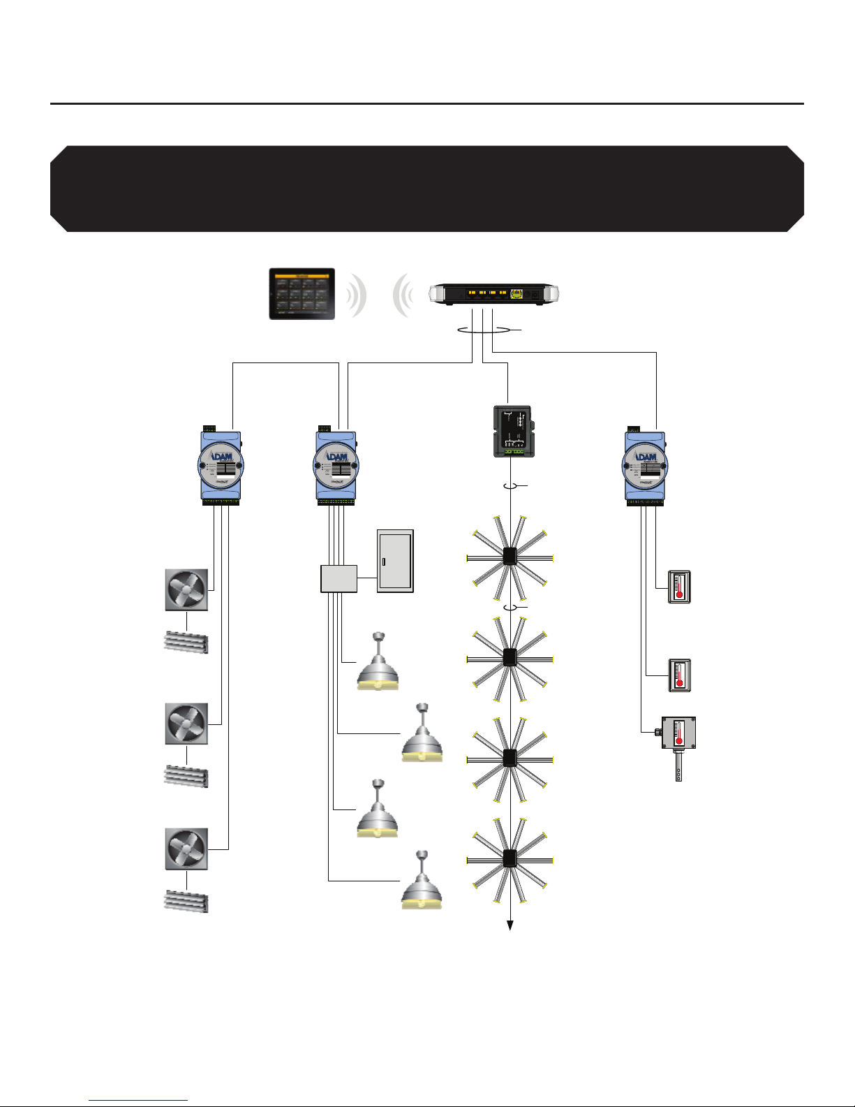
BAFWorks®system diagram
The diagram below shows a typical BAFWorks®installation with fans, lights, exhaust fans and louvers, and temperature sensors.
1. The iPad and Wi-Fi router are located inside the provided wall mounting bracket. The Wi-Fi link must be dedicated to the iPad, as this is your only
means of fan control unless a remote operator station is installed. Big Ass Solutions does not recommend removing the iPad from the mounting
bracket. This will leave you without a means of fan control if the Wi-Fi signal is lost or if the iPad itself is lost. See page 23 for details.
2. ADAM modules can be daisy chained.
3. The BAF gateway is connected locally to the Wi-Fi router. If the gateway is remotely mounted, a customer-supplied 5VDC 100mA power supply must
be used. See page 21 for connection details for the wall-mounted components.
AI1-
AI1+
AI0-
AI0+
AGND
Ethernet
(Port2)
Ethernet
(Port1)
AI2+
AI2-
AI3+
AI3-
AGND
AI4+
AI4-
AI5+
AI5-
AI6+
AI6-
AI7+
AI7-
+VS
GND
RL2NO
RL2COM
RL2NC
RL3NO
RL3COM
RL3NC
RL4NO
RL4COM
RL4NC
RL5NO
RL5COM
RL5NC
N/C
+VS
GND
RL1NC
RL1COM
RL1NO
RL0COM
RL0NO /NC
Ethernet
(Port 2)
Ethernet
(Port 1)
RL2NO
RL2COM
RL2NC
RL3NO
RL3COM
RL3NC
RL4NO
RL4COM
RL4NC
RL5NO
RL5COM
RL5NC
N/C
+VS
GND
RL1NC
RL1COM
RL1NO
RL0COM
RL0NO/N C
Ethernet
(Port 2)
Ethernet
(Port 1)
iPad1
Wi-Fi Router1
CAT5
6 channel
max
6 channel
max Modbus 8 channel
max
Lighting
contactors
Load
center
Modbus
Indoor oor
temperature
Indoor ceiling
temperature
Outdoor
temperature
Up to 32 fans
Lighting branch circuits
Exhaust fans and louvers
ADAM 6160
Ouput modules2
BAF
Gateway3
ADAM 6117
Input module2
After BAFWorks is installed, the iPad® mobile digital device (and fan remote operator station[s], if installed) will be
your only means of fan control. You will not be able to use the wall-mounted controllers included with the fans. Before
installing BAFWorks, install the fan system and wall controllers according to the instructions in the fan Installation
Guide. This will give you a backup means of fan control in case a problem occurs with the BAFWorks system or if you
need to make parameter changes.
BAFWORKS®INSTALLATION GUIDE
3
WWW.BIGASSSOLUTIONS.COM ©2013 DELTA T CORP. ALL RIGHTS RESERVED
BAFWORKS®INSTALLATION GUIDE
Pre-Installation
Parts and hardware
Note: The exact parts and hardware included will vary depending on the components (fans, lighting, ventilation, temperature sensors)
you are connecting to BAFWorks®. The drawings below and on the following page are not to scale.
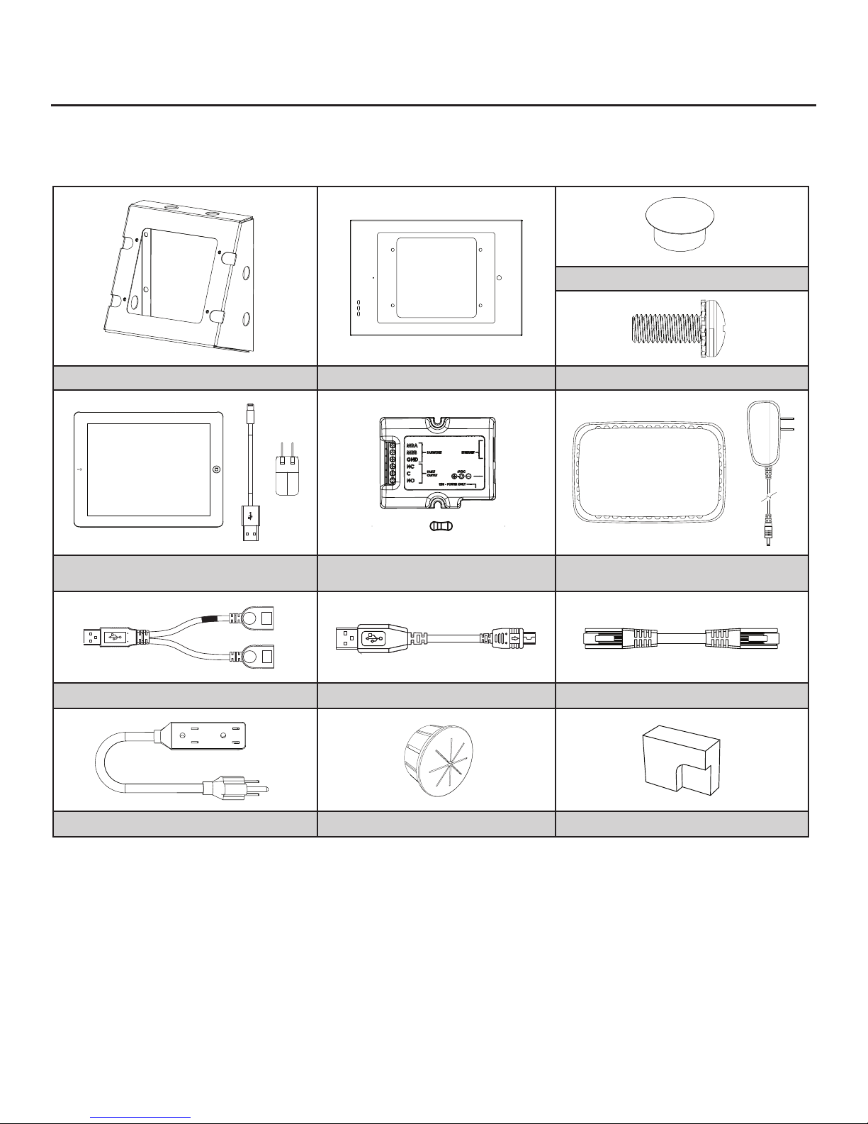
Wall-mounted parts and hardware
(6) Mounting Bracket Knockout
Mounting Bracket iPad® Enclosure1(4) 10-32 x 1/2” Pan Head Screw2
iPad, 36” (914 mm) Data/Charging Cord,
& 2 A USB Charger BAF Gateway & (4) Resistor3Wi-Fi Router & AC Power Adapter4
USB Splitter512” (305 mm) USB Cord612” (305 mm) CAT5 Ethernet Patch Cable
9 ft (2.7 m) Power Cord Bushing Plug Foam Bumper
1. The iPad enclosure includes a key (not shown) for securing access to the iPad.
2. Included with the iPad enclosure
3. Includes two (2) 120 Ω 1/4 W resistors for end of line termination (Brown, Red, Brown, Gold) and two (2) 680 Ω 1/4 W resistors for proper line biasing
where required (Blue, Gray, Brown, Gold. Required for Lenze SMVector VFDs ONLY.)
4. 100–240 VAC 50/60 Hz, 5 VDC @ 1 A
5. Type A Male to Type A Female (with data), Type A Female (power only for BAF gateway). The “power only” side for the gateway is marked with a red
band.
6. Type A Male to Mini B Male
BAFWORKS®INSTALLATION GUIDE
WWW.BIGASSSOLUTIONS.COM ©2013 DELTA T CORP. ALL RIGHTS RESERVED
4Pre-Installation (cont.)
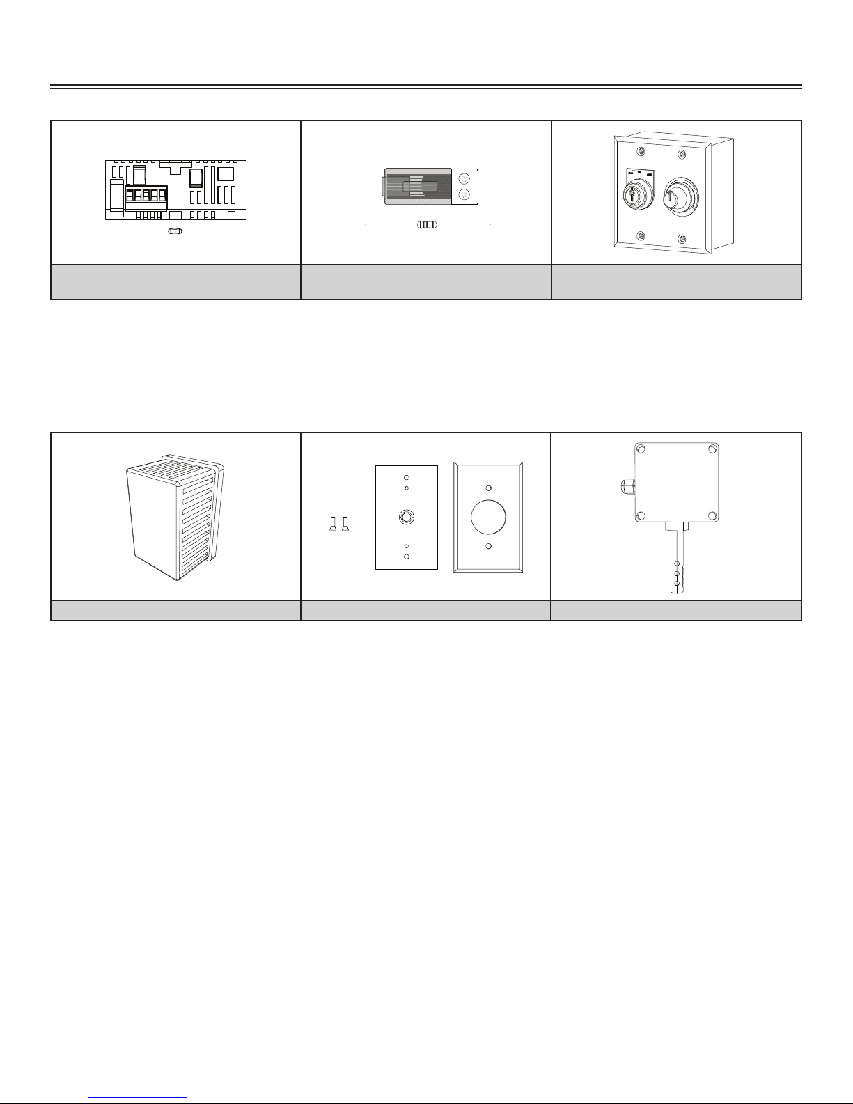
Temperature sensor parts and hardware
Indoor Temperature Sensor Indoor Sensor Mounting Hardware Outdoor Temperature Sensor
Fan parts and hardware
Modbus Communication Card
& 120 Ω 1/4 W Resistor1
RJ45 to Modbus Connector
& 120 Ω 1/4 W Resistor2Remote Operator Station3
1. One (1) Modbus communication card is required for each fan in the BAFWorks® system with a Lenze SMVector VFD.
2. One (1) RJ45 to Modbus connector is required for each fan in the BAFWorks system with a Delta E or M series VFD, or an Allen-Bradley®
PowerFlex® 4, 4M, or 40 VFD.
3. Included only if the remote operator station option is ordered. One remote operator station is required for each fan you plan to control locally. Four (4)
cover screws and two (2) keys for turning the mode selection knob are provided with each remote operator station. See page 37 for remote operator
station installation, operation, and wiring instructions.
5 4 3 2 1
Lighting, ventilation, and automation parts and hardware
The parts, hardware, and wiring required for connecting lights, ventilation, and temperature sensors to the BAFWorks system are
shipped in pre-assembled lighting, input, and output panels. The specic parts included on the panels (input modules, output modules,
etc.) depend on the types of devices you are connecting to the system. See pages 8–15 for panel diagrams and wiring details.

BAFWORKS®INSTALLATION GUIDE
5
WWW.BIGASSSOLUTIONS.COM ©2013 DELTA T CORP. ALL RIGHTS RESERVED
BAFWORKS®INSTALLATION GUIDE
Pre-Installation (cont.)
Pre-installation requirements
1. Identify network to use for BAFWorks®
Choose one of the following:
a. Use the provided NETGEAR®N150 Wi-Fi router.
If the provided Wi-Fi router is used, CAT5 cable must be routed between the router and all ADAM modules (star or daisy chain
topology). Keep in mind that the NETGEAR router includes only four (4) LAN ports; therefore, the maximum number of home runs is
limited to three (3).
b. Use the existing wired or wireless network.
Use this setup in locations where third-party Wi-Fi routers are not approved. Adhere to the following requirements:
• Use of the existing network requires close cooperation and planning with the facility’s network administrator.
• CAT5 cable must be routed between the ADAM modules and the nearest LAN port (star or daisy chain topology).
• CAT5 cable must be routed between the BAF gateway and the nearest LAN port.
• The Wi-Fi and LAN must be part of the same subnet or VPN.
• The iPad® IP address must be in the same range as the ADAM modules and the BAF gateway.
• Firewalls must not block the ports required by the system. Refer to the table below.
UDP/TCP ports used by ADAM modules (initial mode)
Function Protocol Port
UDP ASCII communication UDP 1025
Datastream UDP 5168
GCL IO message UDP 5168
P2P message UDP 1025
Search engine UDP 5048
TCP ASCII/Modbus communication TCP 502
Download TCP 5450
Download Adam6024 TCP 7000
When the ADAM modules are in normal mode, they follow the standard of Ethernet/IP. TCP port number 44818 is used for explicit
messaging and UDP port number 2222 is used for implicit messaging.
2. Identify hardware requirements
Identify the hardware required to interface with the facility’s equipment. Adhere to the following:
a. The lighting panel includes six (6) 4-pole, 20-amp lighting contactors and can control twenty-four (24) 20-amp lighting circuits in six
groups of four. The contactors are 120 VAC coil, but can be ordered with optional coil voltages if needed.
b. The 6 channel relay output panel includes one (1) ADAM 6160 module and can control six (6) loads independently (relay contacts
are limited to 5 A @ 250 VAC each). This panel should be used for interfacing with exhaust fan motor starters, louvers, and lighting
circuits, which are already controlled by lighting contactors.
c. The 12-channel relay output panel includes two (2) ADAM 6160 modules.
d. The 8 channel analog input panel includes one (1) ADAM 6117 module. It supports both voltage (±1, ±5, ±10) and current (±20 mA,
0–20 mA, 4–20 mA). Big Ass Solutions recommends and pre-congures the modules for 4–20mA operation.
i. One controlled fan zone requires two (2) channels (oor temperature sensor and ceiling temperature sensor).
ii. One controlled ventilation zone requires two (2) channels (oor temperature sensor and outdoor temperature sensor).
iii. The oor temperature sensor can be shared by fan automation and ventilation automation (i and ii).
iv. Additional controlled zones (if it is desired to control by temperature independently) will require additional channels and sensors.
e. All panels (a, b, c, and d) include a 30 W, 24 VDC power supply. AC input: 100–277 VAC, 50/60 Hz.
Read and complete all of the following steps prior to BAFWorks®installation!
BAFWORKS®INSTALLATION GUIDE
WWW.BIGASSSOLUTIONS.COM ©2013 DELTA T CORP. ALL RIGHTS RESERVED
6Pre-Installation (cont.)
MAC ID sticker
relocated to outside
of module case
Case Screws
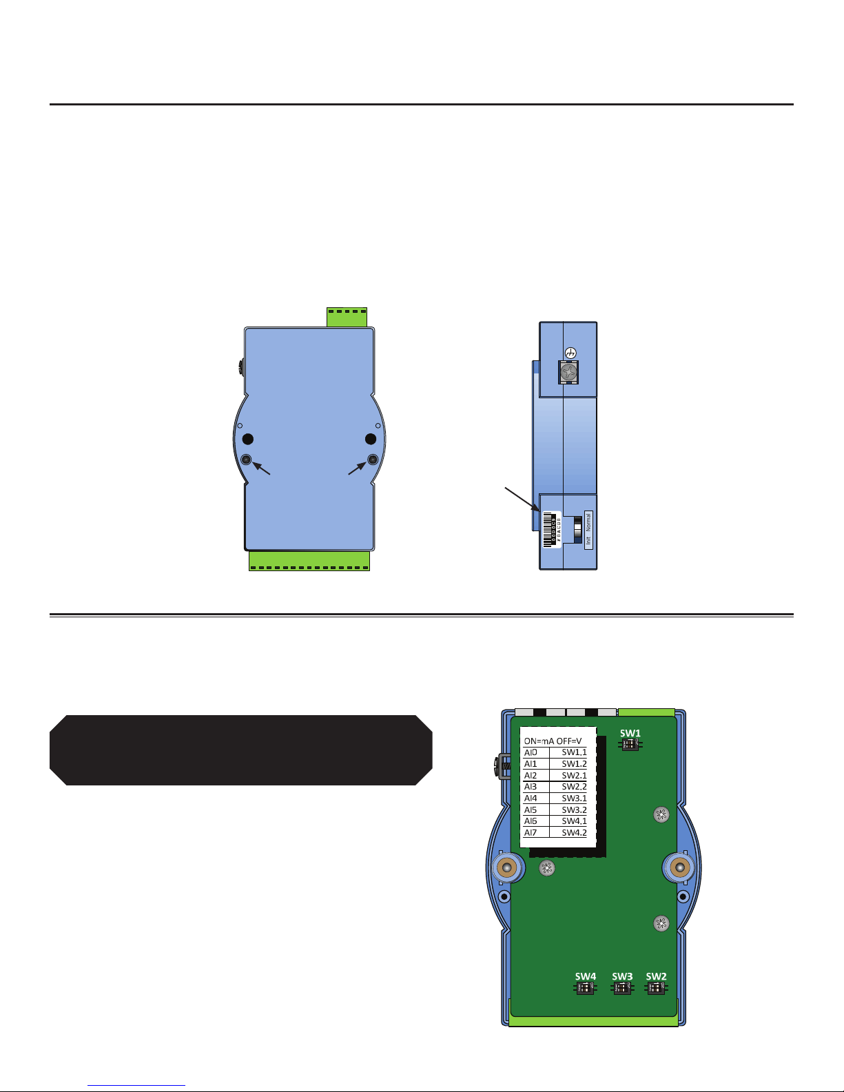
4. Congure signal input type (ADAM 6117 analog input modules only)
The ADAM 6117 module signal input type must be congured for 4–20 mA or 0–10 V. Big Ass Solutions recommends 4–20 mA.
With the case halves separated (see step 3 above), locate the input mode selection switches and set them to 4–20 mA. Refer to the
illustration below.
Back View Side View
Pre-installation requirements (cont.)
3. Obtain ADAM module MAC ID numbers
If multiple ADAM modules of the same module number will be used on the same network, Big Ass Solutions recommends obtaining and
recording each module’s MAC ID number. The MAC ID numbers will be helpful during ADAM module conguration.
To obtain an ADAM module’s MAC ID number:
1. Remove the two (2) small Phillips head screws from the back of the module and separate the case halves. Refer to the illustration
below.
2. Locate the module’s MAC ID sticker on the PC board.
3. Record the MAC ID number on page 58 of this manual and on page 28 of the BAFWorks®User Guide. You can also carefully peel
the sticker off of the PC board and relocate it to the outside of the module case for future reference. Refer to the illustration below.
Set ONLY the input mode selection switches to 4–20
mA. DO NOT toggle any of the other switches inside the
module. These switches are critical to module operation.
Toggling these switches may ruin the module.

BAFWORKS®INSTALLATION GUIDE
7
WWW.BIGASSSOLUTIONS.COM ©2013 DELTA T CORP. ALL RIGHTS RESERVED
BAFWORKS®INSTALLATION GUIDE
Pre-Installation (cont.)
Installation overview
To install BAFWorks, complete the following steps. See the chapters, sections, and pages referenced below for detailed installation
instructions.
1. Install network-enabled hardware
Install, wire, and congure all ADAM modules, lighting/input/output panels, temperature sensors, and other network hardware as
described in “Electrical Installation: Lights, Ventilation, & Automation” on pages 8–18.
2. Install wall-mounted components
Mount the Wi-Fi router, BAF gateway, and iPad® to the wall and connect the wall-mounted components as described in “Mounting
the BAFWorks Control System” on pages 19–22.
3. Install Modbus wiring and congure fans
Install the fan Modbus wiring and complete all fan conguration and wiring as described in “Electrical Installation: Fans” on pages
23–36. If you are installing the remote operator station option, complete all installation and wiring steps in “Fan Remote Operator
Station (Optional)” on pages 37–41.
4. Congure ADAM modules
Download the conguration utility and congure the ADAM modules as described in “Conguring ADAM Modules” on pages 42–44.
5. Add ADAM modules and temperature sensors to BAFWorks
Add and congure the ADAM modules and temperature sensors as described in “Adding Output and Input Modules” on pages
45–46.
6. Congure fan automation settings
Congure the fan group automation settings as described in “Setting Up Fan Group Automation” on page 47.
7. Congure ventilation automation settings
Congure the ventilation group automation settings as described in “Setting Up Ventilation Group Automation” on page 48.
8. Add fans, lights, and ventilation
Add fans, lights, and louvers/vents to the BAFWorks system as described on pages 49–54 of the “Setting Up the BAFWorks
Application” chapter.
Complete all steps in “Pre-Installation Requirements” on page 5 before proceeding.
BAFWORKS®INSTALLATION GUIDE
WWW.BIGASSSOLUTIONS.COM ©2013 DELTA T CORP. ALL RIGHTS RESERVED
8 Electrical Installation: Lights, Ventilation, &
Automation
WARNING: To reduce the risk of electric shock, wiring should be performed by a qualied electrician! Incorrect assembly can
cause electric shock or electrical component damage! Hazard of electrical shock!
WARNING: Installation must be in accordance with the requirements specied in this installation manual and with any
additional requirements set forth by the National Electric Code (NEC), ANSI/NFPA 70-2011, and all local codes. Code
compliance is ultimately YOUR responsibility! Failure to comply with these codes could result in personal injury or property
damage.
CAUTION: The Big Ass Solutions product warranty will not cover equipment damage or failure that is caused by improper
installation.
CAUTION: The following information is merely a guide for proper installation. Big Ass Solutions cannot assume
responsibility for the compliance or the non-compliance to any code, national, local, or otherwise for the proper installation of
this equipment. A hazard of personal injury and/or equipment damage exists if codes are ignored during installation.
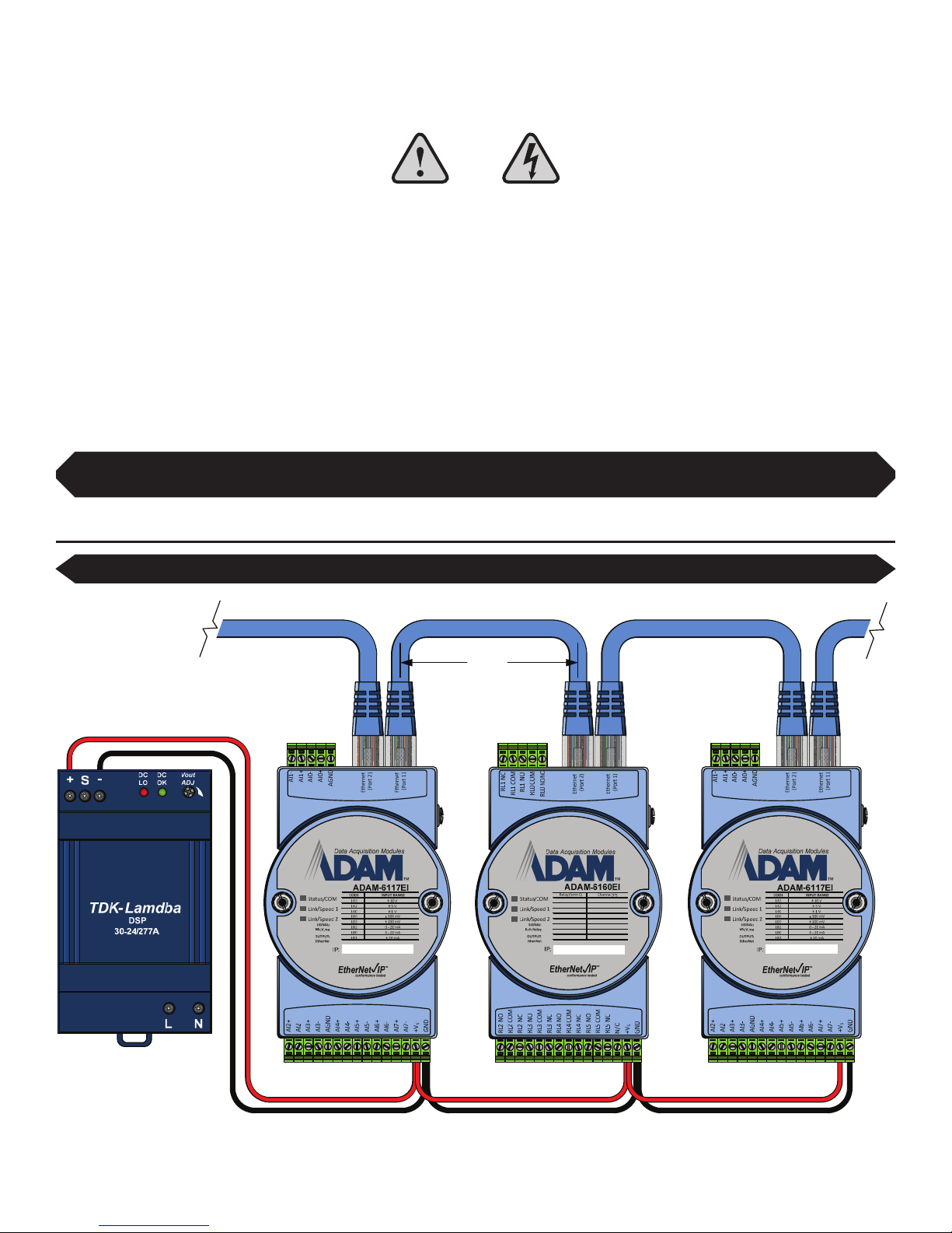
ADAM module basic power and data wiring
In from router
or switch
DC supply rating:
In: 100–277 VAC 50/60 Hz
Out: 24 VDC @ 30 W
ADAM module power consumption: 10–30 VDC, 3.5 W each
ADAM module environmental ratings: 14ºF–158ºF (-10ºC–70ºC), 20–95% RH non-condensing
RED
BLACK
100 m
330 ft
Complete all steps in “Pre-Installation Requirements” on page 5 and ensure that you have read "Installation Overview"
on page 7 before proceeding.
The maximum cable distance allowed between any two devices is 100 m (330 ft).

BAFWORKS®INSTALLATION GUIDE
9
WWW.BIGASSSOLUTIONS.COM ©2013 DELTA T CORP. ALL RIGHTS RESERVED
BAFWORKS®INSTALLATION GUIDE
Basic relay output wiring
The ADAM 6160 relay output module includes six (6) form C relays. These relays are rated for up to 5 A @ 250 VAC and can be used to
directly drive smaller loads, such as lighting contactors or motor starters. For loads that exceed the 5 A rating, the relay outputs can be
used to drive pilot or isolation relays to achieve higher current capacity. Some typical wiring examples are shown below.
Controlling a load directly
Electrical Installation: Lights, Ventilation, & Automation (cont.)
Using a low voltage pilot/isolation relay
ADAM 6160 Relay Output Module
ADAM 6160 Relay Output Module
250 VAC
Line Max
AC Line
Fuse
R
DC Supply
AC Neutral
Load
N.O.
N.C.
Fuse
5A Load Max
AC Neutral/L2
BAFWORKS®INSTALLATION GUIDE
WWW.BIGASSSOLUTIONS.COM ©2013 DELTA T CORP. ALL RIGHTS RESERVED
10 Electrical Installation: Lights, Ventilation, & Automation (cont.)
Basic relay output wiring (cont.)
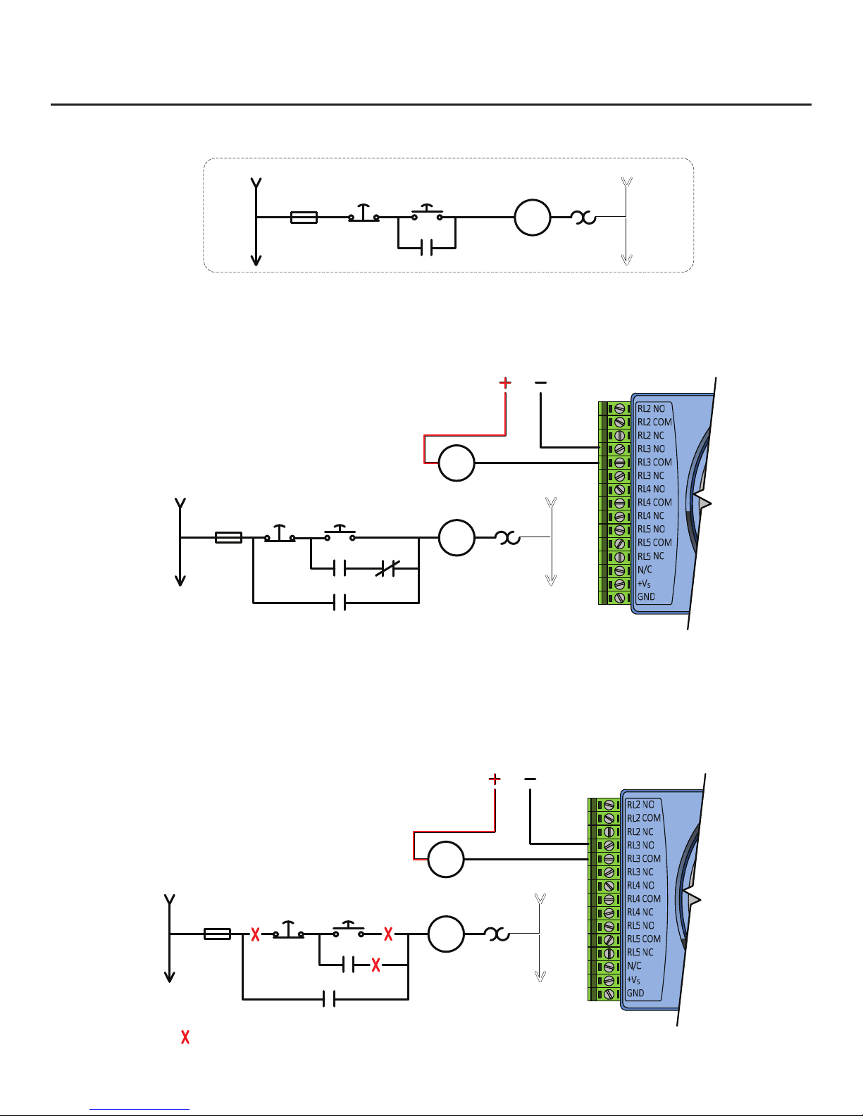
Typical 3-wire combination motor starter control wiring (single station)
Interfacing with 3-wire start/stop circuits
With a low voltage SPDT relay, the existing push
button controls can still be used*.
*The addition of an SPDT pilot relay as shown above allows the use of both iPad® start/stop and the existing start/stop push buttons.
However, relay contact ight time is critical. If the pilot relay's N.C. contact re-closes too quickly upon an iPad stop command relative
to the motor starter's auxiliary contact opening, the motor starter may fail to de-energize if the iPad was used to energize the starter. If
this occurs, the existing start/stop push buttons must be disconnected from the circuit, and the motor starter must be controlled from the
iPad only as shown below.
ADAM 6160 Relay Output Module
ADAM 6160 Relay Output Module
AC Line
AC Line
AC Line
Fuse
Fuse
Fuse
Stop
Stop
Stop
Start
Start
Start
MS
O.L.
AC Neutral
AC Neutral
AC Neutral
DC Supply
DC Supply
R N.O.
R N.O.
R N.C.
MS aux
MS aux
R
R
MS
MS
MS aux
= cut or disconnect
BAFWORKS®INSTALLATION GUIDE
11
WWW.BIGASSSOLUTIONS.COM ©2013 DELTA T CORP. ALL RIGHTS RESERVED
BAFWORKS®INSTALLATION GUIDE
Electrical Installation: Lights, Ventilation, & Automation (cont.)
Basic relay output wiring (cont.)
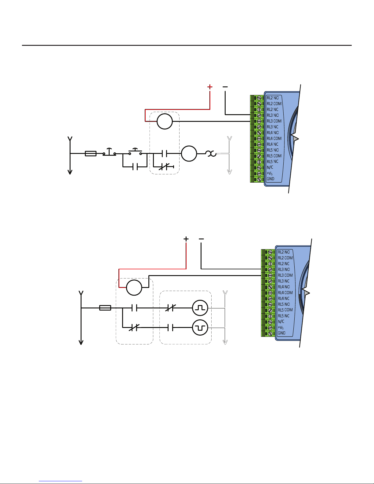
Using the ADAM module and/or pilot relay as a circuit enabler
Shown with low voltage SPDT relay
ADAM 6160 Relay Output Module
Interfacing with mechanically held lighting contactors
With a low voltage SPDT pilot relay
ADAM 6160 Relay Output Module
There are many different topologies for mechanically held contactors. This diagram serves as a generic representation of the
contactor's coil lead functions. The pilot relay's N.O. and N.C. contact are used to alternate the contactor's on and off coil leads. This
diagram can also be used as a basic guide for modifying an electrically held contactor to operate as a mechanically held contactor.
Auxiliary contact ight time is critical in these applications. Normally Closed Late Break and/or Normally Open Early Make auxiliary
contacts may be necessary for proper operation.
Contact the lighting contactor manufacturer if additional details are needed.
AC Line
AC Line
Fuse
Fuse
Stop
N.O.
Start
N.C.
AC Neutral
AC Neutral
DC Supply
DC Supply
R N.O.
N.C.L.B.*
R N.C.
N.O.E.M.*
Lighting Contactor
Pulse ON
Pulse OFF
MS aux
Pilot Relay
R
R
MS

BAFWORKS®INSTALLATION GUIDE
WWW.BIGASSSOLUTIONS.COM ©2013 DELTA T CORP. ALL RIGHTS RESERVED
12 Electrical Installation: Lights, Ventilation, & Automation (cont.)
Basic relay output wiring (cont.)
Using the ADAM module with 3-way or multi-way lighting circuits
Shown with 3-way light switch, 4-way light switch, and low voltage SPDT pilot relay
ADAM 6160 Relay Output Module
Note: ADAM 6160 relay module contacts are rated for 5 A max @ 250 VAC. The relay module contacts can be used to pilot smaller
loads, but use of a pilot relay with a suitable contact rating for the connected load and branch circuit is recommended. When connected
in this fashion, the On/Off status displayed on the iPad®may not represent the actual load state.
AC Line
4-Way 3-Way
Load
AC Neutral
DC Supply
R N.O.
R N.C.
R

BAFWORKS®INSTALLATION GUIDE
13
WWW.BIGASSSOLUTIONS.COM ©2013 DELTA T CORP. ALL RIGHTS RESERVED
BAFWORKS®INSTALLATION GUIDE
Electrical Installation: Lights, Ventilation, & Automation (cont.)
Wiring: 12 x 12 x 4 lighting panel, 6-channel
The standard lighting control panel shown below includes six (6) 4-pole, 20 A contactors with 120 VAC coils. This allows switching of up
to twenty-four (24) 20 A lighting circuits in six (6) groups of four (4) circuits each.
Note: Alternate contactors and coil voltages can be supplied upon request (12–277 V AC/DC).
1
2
2
2
GND
1
1
`
H/F1
N/F2
BLACK
BLACK
BLACK
BLACK
BLACK
BLACK
BROWN
BROWN
BLUE
BLUE
WHITE
WHITE
WHITE
WHITE
WHITE
WHITE
GREEN WITH YELLOW
RED
RED
Note: Only one contactor coil circuit is
shown for clarity (#2). All six contactor
coil circuits (#0–5) will be prewired to the
ADAM module.

BAFWORKS®INSTALLATION GUIDE
WWW.BIGASSSOLUTIONS.COM ©2013 DELTA T CORP. ALL RIGHTS RESERVED
14 Electrical Installation: Lights, Ventilation, & Automation (cont.)
Wiring: 12 x 12 x 4 output panel
1
2
2
2
GND
1
1
H/F1
N/F2
DC+
DC-
DC-
DC-
DC+
DC+
RED
RED
RED
RED
BLACK
BLACK
BLACK
BLACK
BLACK
BLACK
BLUE
BLUE
BLUE
BLUE
BROWN
BROWN
BROWN
BROWN
WHITE
WHITE
WHITE
WHITE
WHITE
GREEN WITH YELLOW
GREEN WITH YELLOW
OUT to 24 VDC load/pilot
relay; wired N.O.
OUT to AC line powered load/pilot
relay; wired N.O.
Table of contents


