Page 2 of 2 DF-52095 06/18/04
Maximum battery charging capability: 18 AH.
Initiating Device Circuits (zones)Initiating Device Circuits (zones)
Initiating Device Circuits (zones)Initiating Device Circuits (zones)
Initiating Device Circuits (zones)
Ten Style B (Class B).
Zones may be programme for:
Two-wire smoke etectors an any normally open
contact evice.
Zones 1 - 8 configure as general alarm zones only.
Zones 9 an 10 can be configure as smoke zones
or supervisory alarm zones.
All circuits are power-limite an supervise , meeting
the latest requirements using fuseless technology.
Notification Appliance (Bell) CircuitsNotification Appliance (Bell) Circuits
Notification Appliance (Bell) CircuitsNotification Appliance (Bell) Circuits
Notification Appliance (Bell) Circuits
(NACs)(NACs)
(NACs)(NACs)
(NACs)
Two Style Y (Class B) @ 1.25 amps (expan able to 2.5
amps) each.
NACs may be programme :
Silenceable.
Non-Silenceable.
Auto-Silence (program 5 to 20 minutes).
All circuits are power-limite an supervise , meeting
the latest requirements using fuseless technology.
Auxiliary OutputsAuxiliary Outputs
Auxiliary OutputsAuxiliary Outputs
Auxiliary Outputs
Resettable four-wire smoke etector power @ 300 mA.
Non-resettable power @ 500 mA.
NOTE: Total current for auxiliary power outputs and two NACs
must not exceed 6.0 amps. Total system current in excess of 3.6
amps requires the optional XR -24 transformer and 12 or 18 AH
batteries.
Integral Form-C Alarm, Trouble an Supervisory relays,
rate at: 2.0 amps @ 30 VDC (resistive), 2.0 amps @ 30
VAC (resistive).
EIA-4 5 Port, Compatible DevicesEIA-4 5 Port, Compatible Devices
EIA-4 5 Port, Compatible DevicesEIA-4 5 Port, Compatible Devices
EIA-4 5 Port, Compatible Devices
LED-10IM: EIA-485 Interface Mo ule. Provi es MS-
2410B with EIA-485 output, capable of supporting up to 10
compatible EIA-485 evices.
LED-10 Series: LED-type fire annunciators capable of
isplaying Alarm (re ) an Trouble (yellow) LEDs for all
ten Initiating Device Circuits (IDCs).
AFM Series: LED-type fire annunciators capable of pro-
vi ing up to 16 zones of Alarm (re ) annunciation an com-
mon system trouble LED. Mount to 4-gang electrical box
ONLY.
LDM Series: Lamp Driver Mo ule series for use with
custom graphic annunciators.
ACM-8RF: Remote Form-C relay mo ule. Provi es eight
mappable Form-C relays riven by EIA-485 for relay-by-
zone capability (two minimum require for relay-by-zone).
Each requires ABS-8RF for mounting.
NOTE: For more detailed information on Compatible EIA-485
Devices for use with the MS-2410B, please refer to the LED- 0,
AFM/AFM-X, LDM or ACM-8RF data sheets, document numbers
DF-51500, DF-514 5, DF-51384, and DF-51555 respectively.
Cabinet SpecificationsCabinet Specifications
Cabinet SpecificationsCabinet Specifications
Cabinet Specifications
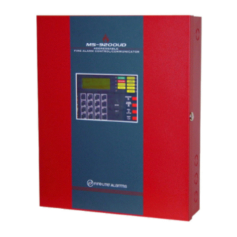
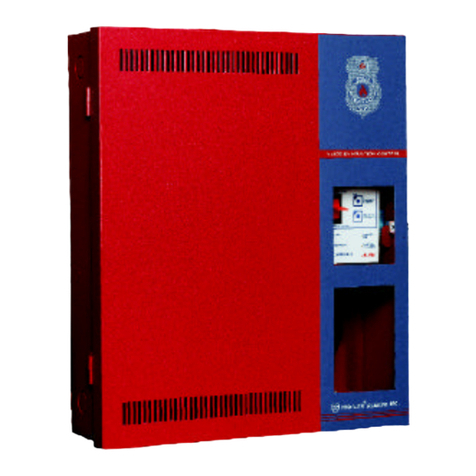
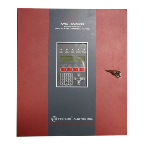
See iagrams below.
PRO UCT LINE INFORMAPRO UCT LINE INFORMA
PRO UCT LINE INFORMAPRO UCT LINE INFORMA
PRO UCT LINE INFORMATIONTION
TIONTION
TION
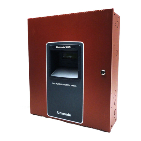
MS-2410B 24-Volt, 10-zone, Class B, FACP.
XRM-24 120VAC, 100 VA transformer. Expan s total
system power from 3.6 amps to 6.6 amps.
RTB Remote Trouble Buzzer.
4XTMF Remote station output or municipal box con-
nection (reverse polarity application).
L D-10IM EIA-485 port interface mo ule. Required for
use with EIA-485 compatible de ices (see
abo e).
DP-2410B Optional internal ea -front ress panel.
TR-4-R Flush mount trim ring.
BB-17F UL liste battery backbox. Required for use
with batteries o er 12 AH.
ABS-8RF Metal enclosure for mounting each ACM-8RF
mo ule.
2410RB Replacement motherboar .
BAT-12120 Battery, 12 volt, 12.0 AH (two required).
BAT-12180 Battery, 12 volt, 18.0 AH (two required; requires
BB-17F battery backbox for mounting).
52095box.wmf

