STINAR DPT-512 Manual

sales@stinar.com |P651.454.5112 |F651.454.5143 |www.stinar.com
DISABLED PASSENGER LIFT
OPERATION & MAINTENANCE MANUAL
MODEL: DPT-512
SERIAL NO: 25781
MANUFACTURE DATE: 09/2021
REV.02.2022

Disabled Passenger Lift DPT-512 | 2
Eective Pages SECTION PAGE DATE
Title Page 1October 2021
List of Eective Pages 2October 2021
Contents 3-5 October 2021
Introduction 6October 2021
SECTION 1
Introduction 7-10 October 2021
Section 1-1 11-30 October 2021
Section 1-2 31-44 October 2021
Section 1-3 45-48 October 2021
SECTION 2
Introduction 49 October 2021
Section 2-1 50-56 October 2021
Section 2-2 57-71 October 2021
Section 2-3 72-74 October 2021
SECTION 3
Introduction 75 October 2021
SECTION 4
Introduction 76 October 2021
Section 4-1 77 October 2021
Section 4-2 78 October 2021
Parts Order Form 79 October 2021
FIGURES
Disabled Passenger Transporter, Model DPT-512 80-83 October 2021
Electrical System 84-89 October 2021
Hydraulic System 90-91 October 2021
Scissors Assembly 92-93 October 2021
Platform Assembly 94-95 October 2021
Van body Interior 96-98 October 2021
Rear Stabilizer Assembly 99-100 October 2021
Front Stabilizer Assembly 101-102 October 2021
Emergency Lift Gate Manual Override
Schematic 103-104 October 2021
Electrical Box Interior 105-106 October 2021
Cab Controls and Indicators 107-108 October 2021
Van Body Control Station 109-110 October 2021
Rear Van Control Station 111-112 October 2021

Disabled Passenger Lift DPT-512 | 3
Table of Contents MANUAL OVERVIEW � � � � � � � � � � � � � � � � � � � � � � � � � � 7
SECTION 1 | GENERAL INFORMATION & OPERATING
PROCEDURES � � � � � � � � � � � � � � � � � � � � � � � � � � � � � � 8
1�1 | Description � � � � � � � � � � � � � � � � � � � � � � � � � � � 11
1.1.1 | Equipment Systems and Components . . . . . . . . . . . . . . . . . . . 11
1.1.1.1 | Truck Chassis-cab . . . . . . . . . . . . . . . . . . . . . . . . . . . . . . . . . . . . . . 11
Figure 1.1.1 | Disabled Passenger Transporter, Model DPT-512. . . . . . . . .12
Figure 1.1.1 | Disabled Passenger Transporter, Model DPT-512. . . . . . . . .13
1.1.2 | Hydraulic Stabilizers. . . . . . . . . . . . . . . . . . . . . . . . . . . . . . . . . . . 14
1.1.3 | Body Lift Mechanism . . . . . . . . . . . . . . . . . . . . . . . . . . . . . . . . . . 14
1.1.4 | Van Body . . . . . . . . . . . . . . . . . . . . . . . . . . . . . . . . . . . . . . . . . . . . . 15
1.1.5 | Front Platform . . . . . . . . . . . . . . . . . . . . . . . . . . . . . . . . . . . . . . . . 16
1.1.6 | Screen Guard . . . . . . . . . . . . . . . . . . . . . . . . . . . . . . . . . . . . . . . . . 16
1.1.7 | Power Lift Gate . . . . . . . . . . . . . . . . . . . . . . . . . . . . . . . . . . . . . . . 16
1.1.8 | Generator Set and Related Components . . . . . . . . . . . . . . . . . 17
Figure 1.1.9 | Hydraulic System Schematic . . . . . . . . . . . . . . . . . . . . . . . . . .18
1.1.9 | Hydraulic System. . . . . . . . . . . . . . . . . . . . . . . . . . . . . . . . . . . . . . 19
1.1.10 | Power Lift Gate Electro-Hydraulic System . . . . . . . . . . . . . . . 21
Figure 1.1.10 | Hydraulic Component Group . . . . . . . . . . . . . . . . . . . . . . . . .22
1.1.11 | Electrical System . . . . . . . . . . . . . . . . . . . . . . . . . . . . . . . . . . . . . 23
1.1.11.1 | Master Control Switch . . . . . . . . . . . . . . . . . . . . . . . . . . . . . . . . . . 27
1.1.11.2 | Intercom . . . . . . . . . . . . . . . . . . . . . . . . . . . . . . . . . . . . . . . . . . . . . 27
Figure 1.1.11 | Electrical System Schematic (Page 1 of 4) . . . . . . . . . . . . . .28
Figure 1.1.11 | Electrical System Schematic (Page 2 of 4) . . . . . . . . . . . . . .29
Figure 1.1.11 | Electrical System Schematic (Page 3 of 4) . . . . . . . . . . . . . .30
Figure 1.1.11 | Electrical System Schematic (Page 4 of 4) . . . . . . . . . . . . . .31
1�2 | Operation � � � � � � � � � � � � � � � � � � � � � � � � � � � � 32
1.2.1 | Operating Controls and Indicators . . . . . . . . . . . . . . . . . . . . . . . .32
1.2.1.1 | Cab Controls and Indicators (See Figure 1.2.1.1) . . . . . . . . . . . . 32
Figure 1.2.1.1 | Cab Controls and Indicators . . . . . . . . . . . . . . . . . . . . . . . . .33
1.2.1.3 | Van Body Control Station (See Figure 1.2.1.3) . . . . . . . . . . . . . . . 34
1.2.1.4 | Rear Control Box . . . . . . . . . . . . . . . . . . . . . . . . . . . . . . . . . . . . . . 35
Figure 1.2.1.3 | Van Body Control Station . . . . . . . . . . . . . . . . . . . . . . . . . . .36
1.2.1.5 | Generator Set Operating Controls . . . . . . . . . . . . . . . . . . . . . . . 37
1.2.1.6 | Mini Split Unit Operating Controls. . . . . . . . . . . . . . . . . . . . . . . . . 37
1.2.1.7 | Emergency Operating Controls (See Figure 1.2.1.7) . . . . . . . . . . . . . 37
Figure 1.2.1.7 | Emergency Operating Controls . . . . . . . . . . . . . . . . . . . . . .38
1.2.2 | Pre-Operation Checks . . . . . . . . . . . . . . . . . . . . . . . . . . . . . . . . . 39
1.2.3 | Operating Procedures – Normal Operation . . . . . . . . . . . . . . 40
1.2.3.1 | Starting and Driving Unit – Engine and Transmission . . . . . . . . . 40
1.2.3.2 | Operating the Hydraulic Pump . . . . . . . . . . . . . . . . . . . . . . . . . . 40

Disabled Passenger Lift DPT-512 | 4
1.2.3.3 | Operating Stabilizers . . . . . . . . . . . . . . . . . . . . . . . . . . . . . . . . . . . 40
1.2.3.5 | Operating Over-Cab Platform . . . . . . . . . . . . . . . . . . . . . . . . . . . 41
1.2.3.6 | Operating Rear Lift Gate. . . . . . . . . . . . . . . . . . . . . . . . . . . . . . . . 41
1.2.3.7 | Operating Generator Set . . . . . . . . . . . . . . . . . . . . . . . . . . . . . . . 42
1.2.3.8 | Operating Van Mini Split Unit . . . . . . . . . . . . . . . . . . . . . . . . . . . . 42
1.2.3.9 | Operating Intercom System . . . . . . . . . . . . . . . . . . . . . . . . . . . . . 42
1.2.3.10 | Emergency Lift Gate Manual Override. . . . . . . . . . . . . . . . . . . 42
1.2.4 | Transporting Passengers. . . . . . . . . . . . . . . . . . . . . . . . . . . . . . . 43
1.2.5 | Emergency Operating Procedures . . . . . . . . . . . . . . . . . . . . . . 44
1.2.5.1 | Emergency Shutdown Procedure . . . . . . . . . . . . . . . . . . . . . . . . 44
1.2.5.2 | Emergency Van Body Lowering Procedure . . . . . . . . . . . . . . . . 44
1.2.5.3 | Emergency Hydraulic System Operation . . . . . . . . . . . . . . . . . . 45
1.3 | Specications & Capabilities � � � � � � � � � � � � � � � � � 46
1.3.1 | General Specications . . . . . . . . . . . . . . . . . . . . . . . . . . . . . . . . . 46
1.3.2 | Dimensions . . . . . . . . . . . . . . . . . . . . . . . . . . . . . . . . . . . . . . . . . . 46
1.3.3 | Truck Cab and Chassis . . . . . . . . . . . . . . . . . . . . . . . . . . . . . . . . . 46
1.3.4 | Hydraulic System . . . . . . . . . . . . . . . . . . . . . . . . . . . . . . . . . . . . . 48
1.3.5 | Power Lift Gate . . . . . . . . . . . . . . . . . . . . . . . . . . . . . . . . . . . . . . . 49
1.3.6 | Mini Split Unit . . . . . . . . . . . . . . . . . . . . . . . . . . . . . . . . . . . . . . . . 49
SECTION 2 | SERVICING THE HIGH LIFT TRUCK� � � � � � � � � � � 50
2�1 | Servicing � � � � � � � � � � � � � � � � � � � � � � � � � � � � � 51
2.1.1 | Use of Maintenance Stops . . . . . . . . . . . . . . . . . . . . . . . . . . . . . . 51
2.1.2 | Truck Chassis-Cab. . . . . . . . . . . . . . . . . . . . . . . . . . . . . . . . . . . . . 51
2.1.2.1 | General Engine/Chassis Servicing . . . . . . . . . . . . . . . . . . . . . . . . 51
2.1.3 | Structural Components . . . . . . . . . . . . . . . . . . . . . . . . . . . . . . . . 51
2.1.3.1 | Sheet, Bar, and Tubular Member (Non-Load Bearing) . . . . . . . 51
2.1.4 | Scissors and Platform . . . . . . . . . . . . . . . . . . . . . . . . . . . . . . . . . 51
2.1.5 | Hydraulic System . . . . . . . . . . . . . . . . . . . . . . . . . . . . . . . . . . . . . 51
2.1.5.1 | Hydraulic Oil Tank . . . . . . . . . . . . . . . . . . . . . . . . . . . . . . . . . . . . . . 51
2.1.5.2 | Hydraulic Oil Filters . . . . . . . . . . . . . . . . . . . . . . . . . . . . . . . . . . . . . 52
2.1.5.3 | Pressure Relief Valve. . . . . . . . . . . . . . . . . . . . . . . . . . . . . . . . . . . . 52
2.1.5.4 | Hydraulic Pump and Clutch . . . . . . . . . . . . . . . . . . . . . . . . . . . . . 52
2.1.5.5 | Flow Control Valve, Van Body. . . . . . . . . . . . . . . . . . . . . . . . . . . . 52
2.1.5.6 | Hydraulic Pressure Switch . . . . . . . . . . . . . . . . . . . . . . . . . . . . . . . 52
2.1.6 | Electrical System . . . . . . . . . . . . . . . . . . . . . . . . . . . . . . . . . . . . . 53
2.1.6.1 | Truck Batteries . . . . . . . . . . . . . . . . . . . . . . . . . . . . . . . . . . . . . . . . . 53
2.1.6.2 | Control and Limit Switches . . . . . . . . . . . . . . . . . . . . . . . . . . . . . . 53
2.1.6.3 | Electrical Cables, Wiring, and Lights . . . . . . . . . . . . . . . . . . . . . . 53
2.1.7 | Scheduled Service. . . . . . . . . . . . . . . . . . . . . . . . . . . . . . . . . . . . . 54
2.1.8 | Non-Scheduled Servicing . . . . . . . . . . . . . . . . . . . . . . . . . . . . . . 55
2.1.9 | Lubrication . . . . . . . . . . . . . . . . . . . . . . . . . . . . . . . . . . . . . . . . . . . 55
2.1.9.1 | Truck Chassis. . . . . . . . . . . . . . . . . . . . . . . . . . . . . . . . . . . . . . . . . . . 55
2.1.9.2 | Tracks . . . . . . . . . . . . . . . . . . . . . . . . . . . . . . . . . . . . . . . . . . . . . . . . 55
2.1.9.3 | Scissors Lift . . . . . . . . . . . . . . . . . . . . . . . . . . . . . . . . . . . . . . . . . . . . 55

Disabled Passenger Lift DPT-512 | 5
2.1.9.4 | Front Platform. . . . . . . . . . . . . . . . . . . . . . . . . . . . . . . . . . . . . . . . . . 56
2.1.9.5 | Lubrication Table. . . . . . . . . . . . . . . . . . . . . . . . . . . . . . . . . . . . . . . 56
2.1.9.6 | Special Lubrication Notes . . . . . . . . . . . . . . . . . . . . . . . . . . . . 56
Figure 2.1.9.3 | Lubrication Points . . . . . . . . . . . . . . . . . . . . . . . . . . . . . . . . .57
2.2 | Troubleshooting � � � � � � � � � � � � � � � � � � � � � � � � 58
2.2.1 | Troubleshooting Table . . . . . . . . . . . . . . . . . . . . . . . . . . . . . . . . . 59
Figure 2.2.1 | Hydraulic System Schematic . . . . . . . . . . . . . . . . . . . . . . . . . .63
Figure 2.2.2 | Electrical System Schematic (Page 1 of 4). . . . . . . . . . . . . . .69
Figure 2.2.2 | Electrical System Schematic (Page 2 of 4). . . . . . . . . . . . . . .70
Figure 2.2.2 | Electrical System Schematic (Page 3 of 4). . . . . . . . . . . . . . .71
Figure 2.2.2 | Electrical System Schematic (Page 4 of 4). . . . . . . . . . . . . . .72
2�3 | Adjustments � � � � � � � � � � � � � � � � � � � � � � � � � � 73
2.3.1 | Hydraulic Pressure Relief Valve Adjustment . . . . . . . . . . . . . . 73
2.3.2 | Flow Control Valve Adjustment . . . . . . . . . . . . . . . . . . . . . . . . . 73
2.3.2.1 | Increasing the rate . . . . . . . . . . . . . . . . . . . . . . . . . . . . . . . . . . . . . 73
2.3.2.2 | Decreasing the rate. . . . . . . . . . . . . . . . . . . . . . . . . . . . . . . . . . . . 73
2.3.3 | Bleeding Air from Hydraulic Lines . . . . . . . . . . . . . . . . . . . . . . 73
Figure 2.3.1 | Hydraulic Component Group . . . . . . . . . . . . . . . . . . . . . . . . .74
2.3.4 | Hydraulic Pressure Switch Adjustment . . . . . . . . . . . . . . . . . . 75
SECTION 3 | OVERHAUL � � � � � � � � � � � � � � � � � � � � � � � � 76
3.1 | Truck Chassis-cab � � � � � � � � � � � � � � � � � � � � � � � 76
SECTION 4 | PARTS LIST � � � � � � � � � � � � � � � � � � � � � � � � 77
4.1 | Manufacturer Identication � � � � � � � � � � � � � � � � � � 78
4.2 | Detailed Parts List � � � � � � � � � � � � � � � � � � � � � � � 79
4.2.1 | Understanding the Columns . . . . . . . . . . . . . . . . . . . . . . . . . . . 79
4.2.1.1 | Figure/Item No. . . . . . . . . . . . . . . . . . . . . . . . . . . . . . . . . . . . . . . . . 79
4.2.1.2 | Manufacturer’s Part No. . . . . . . . . . . . . . . . . . . . . . . . . . . . . . . . . 79
4.2.1.3 | Description. . . . . . . . . . . . . . . . . . . . . . . . . . . . . . . . . . . . . . . . . . . . 79
4.2.1.4 | Vendor Code . . . . . . . . . . . . . . . . . . . . . . . . . . . . . . . . . . . . . . . . . 79
4.2.1.5 | QTY . . . . . . . . . . . . . . . . . . . . . . . . . . . . . . . . . . . . . . . . . . . . . . . . . . 79
4.2.2 | Instructions for Ordering Parts and Assemblies . . . . . . . . . . 79
PARTS ORDER FORM � � � � � � � � � � � � � � � � � � � � � � � � � � 80
Figure 4.2.1 | Disabled Passenger Transporter, Model DPT-512 (1 of 2). .81
Figure 4.2.1 | Disabled Passenger Transporter, Model DPT-512 (2 of 2). .82
Figure 4.2.2 | Electrical System (Page 1 of 4) . . . . . . . . . . . . . . . . . . . . . . . .85
Figure 4.2.2 | Electrical System (Page 2 of 4) . . . . . . . . . . . . . . . . . . . . . . . .86
Figure 4.2.2 | Electrical System (Page 3 of 4) . . . . . . . . . . . . . . . . . . . . . . . .87
Figure 4.2.2 | Electrical System (Page 4 of 4) . . . . . . . . . . . . . . . . . . . . . . . .88
Figure 4.2.3 | Hydraulic System. . . . . . . . . . . . . . . . . . . . . . . . . . . . . . . . . . . .91
Figure 4.2.4 | Scissors Assembly . . . . . . . . . . . . . . . . . . . . . . . . . . . . . . . . . . .93

Disabled Passenger Lift DPT-512 | 6
Figure 4.2.5 | Platform Assembly . . . . . . . . . . . . . . . . . . . . . . . . . . . . . . . . . .95
Figure 4.2.6 | Van body Interior (Page 1 of 2) . . . . . . . . . . . . . . . . . . . . . . . .97
Figure 4.2.6 | Van body Interior (Page 2 of 2) . . . . . . . . . . . . . . . . . . . . . . . .98
Figure 4.2.7 | Rear Stabilizer Assembly . . . . . . . . . . . . . . . . . . . . . . . . . . . .100
Figure 4.2.8 | Front Stabilizer Assembly . . . . . . . . . . . . . . . . . . . . . . . . . . .102
Figure 4.2.10 | Electrical Box Interior . . . . . . . . . . . . . . . . . . . . . . . . . . . . . .105
Figure 4.2.11 | Cab Controls and Indicators . . . . . . . . . . . . . . . . . . . . . . . .107
Figure 4.2.12 | Van Body Control Station . . . . . . . . . . . . . . . . . . . . . . . . . . .109
Figure 4.2.13 | Rear Van Control Station . . . . . . . . . . . . . . . . . . . . . . . . . . .111

Disabled Passenger Lift DPT-512 | 7
This publication provides operating and maintenance instructions,
including detailed part lists for the Maintenance High Lift Truck, Model
MHL-216. This truck was manufactured by:
Stinar, LLC
500 Stinar Way
Blooming Prairie, MN 55917
Section 1 | General Information & Operating
Instructions
Includes a unit description, recommended procedures for operation, plus
specications and capabilities.
Section 2 | Servicing The High Lift Truck
Provides unit maintenance information, service and lubrication data, a
troubleshooting guide, and adjustment information.
Section 3 | Maintenance
Presents instructions for component maintenance and repair.
Section 4 | Parts List
Contains a manufacturers’ list, and illustrated part lists for the
assemblies, subassemblies, and systems within the unit.
MANUAL OVERVIEW

Disabled Passenger Lift DPT-512 | 8
SECTION 1 | GENERAL INFORMATION & OPERATING PROCEDURES
SAFETY ALERT SYMBOL – Look for this symbol to point out important
safety precautions.
DANGER: The word “DANGER” denotes a most serious specic potential
hazard. A forbidden practice should denitely be avoided in connection
with a serious hazard.
WARNING: The word “WARNING” is used to denote a specic potential or
hidden hazard which, if not avoided, has the potential for serious injury.
CAUTION: The word “CAUTION” is used to denote a general reminder of
good safety practices or to direct attention to unsafe practices. Following
safe behavioral practices consistent with operating and maintenance
instructions will help the operator and others avoid accident involvement.
NOTE: The word “NOTE” is used to denote something that can cause minor
machine damage or poor performance if ignored.
IMPORTANT: The word “IMPORTANT” informs the reader of something
they need to know to prevent minor machine damage if a certain
procedure is not followed.
General Safety
• Do not rush
• Do not alter your machine
• Read and follow all warning labels. Replace any labels that are
missing or illegible.
• Check all controls and operating functions of the machine in a safe
area before starting work
• Never allow unauthorized persons around machinery when
performing operation functions
• A re extinguisher and rst aid kit should be carried in the truck at
all times
SECTION 1 | GENERAL INFORMATION & OPERATING PROCEDURES
NOTE:
Example
WARNING!
Example
DANGER!
Example
CAUTION!
Example

Disabled Passenger Lift DPT-512 | 9
SECTION 1 | GENERAL INFORMATION & OPERATING PROCEDURES
Before Operation
1. Perform a general all-around visual inspection and equipment check
of the entire unit
2. Check all markings and nameplates for legibility.
3. Perform any checks required by airport or airline regulations
4. Always determine hydraulic oil level and ll tank to proper level
with all hydraulic cylinders fully retracted. Overlling may occur if
cylinders are not retracted which may damage the system
5. If operating at night, check compartment lights for proper operation.
6. Check lights, horn, mirrors, wipers, safety belt, and all other safety
equipment for proper operation
During Operation
Engine and Transmission
• To operate the engine, refer to the truck operator’s manual for
recommended engine starting and operating procedures
• Failure to follow towing procedure may result in transmission
damage. Please check the manufacturer’s recommendations before
towing your unit
• These procedures are suggested general operating procedures. For
specic aircraft servicing, follow procedures specied by your airline
After Operation
• Stop engine and allow machine to come to a complete stop before
leaving the cab or allowing anyone near the unit
• Remove ignition key when parked
Service Safety
• Do not clean, adjust or service this unit while it is in motion
• Periodically check tightness of nuts and bolts, and check for loose,
worn or misaligned parts. Use only approved replacement parts.
• Any new components installed during repair must include the
current safety signs specied by Stinar.
• Perform all work in accordance with authorized standard shop
practices.
• Perform no welding, cutting, patching, and such on any load bearing
or supporting structure. If such repairs are necessary, contact the
Engineering department of Stinar before making any alterations.
• Do not mix hydraulic oils of dierent specications. Oils may not

Disabled Passenger Lift DPT-512 | 10
SECTION 1 | GENERAL INFORMATION & OPERATING PROCEDURES
be compatible and could result in damage to hydraulic system
components.
• A thin oil lm should be visible on the hydraulic cylinder shaft. A
steady drip of oil indicates a need for service.
• Should there be a hydraulic system associated with this unit, always
determine hydraulic oil level and ll tank to the proper level with all
hydraulic actuating cylinders fully retracted. Otherwise, damage may
occur to the tank when the system is operated.
Your safety and the safety of those around you depend upon the operator
using care and good judgment in the operation of this unit. Know the
positions and functions of all controls before attempting to operate.
All equipment has limitations. Understand the speed, braking, steering,
stability and load characteristics of the unit before starting operation.
READ YOUR OPERATOR’S MANUAL!

Disabled Passenger Lift DPT-512 | 11
SECTION 1 | GENERAL INFORMATION & OPERATING PROCEDURES
The Stinar Disabled Passenger Transporter Model DPT-512, is a truck
mounted aircraft service vehicle designed for transporting injured or
disabled personnel to and from aircraft.
The vehicle consists of a truck chassis cab equipped with a hydraulic scissors
lift mechanism capable of elevating the van body to aircraft door threshold
heights of 90 to 228 inches (2286 to 5791 mm). A hydraulic rear lift gate
transfers passengers between ground level and the van body.
The van body has a rated capacity of 3000 pounds (1361 kg). Hydraulically
operated stabilizers are provided for stabilizing the vehicle whenever the
van body is raised.
The scissors lift and the stabilizers are powered by a hydraulic pump driven
from the trucks transmission. The hydraulic pump functions only when the
PTO is turned on from the cab control station. The van lights, the controls,
and the linear actuator on the front platform are all run o the truck’s 12
VDC electrical system. A hand hydraulic pump provides hydraulic power for
emergency use.
The unit is designed to transport personnel on airport ramp areas, service
roads, and public highways.
1.1.1 | Equipment Systems and
Components
The major operating systems and components of the Disabled Passenger
Transporter are described in the paragraphs below. See Figure 1.1.1 for the
locations of components.
1.1.1.1 | Truck Chassis-cab
The Disabled Passenger Transporter is built on a Ford F-550, 4 x 2 chassis
cab and is powered by a 6.8 liter, V-10 gas engine. The transmission is a
5-speed automatic. The chassis is equipped with dual rear wheels.
Controls and indicators added to the cab include:
• Van body raise/lower controls
• Stabilizer raise/lower controls
• Flashing beacon on/o switch
• PTO on/o switch
• Front/rear on/o oodlights
• Van body lighting on/o controls
1.1 | DESCRIPTION

Disabled Passenger Lift DPT-512 | 12
FIGURE 1.1.1 | DISABLED PASSENGER TRANSPORTER, MODEL DPT-512
32
1
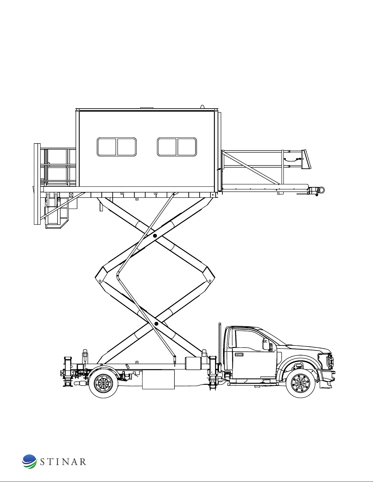
Disabled Passenger Lift DPT-512 | 13
FIGURE 1.1.1 | DISABLED PASSENGER TRANSPORTER, MODEL DPT-512
32
1

Disabled Passenger Lift DPT-512 | 14
SECTION 1 | GENERAL INFORMATION & OPERATING PROCEDURES
The truck includes the following features:
Hydraulic pump and PTO- mounted on transmission. This unit is driven by
the transmission through a hydraulically engaged clutch mounted directly
to the hydraulic pump. It runs on demand whenever the engine is running,
the PTO switch is ON, and a stabilizer up or down or body up control
switch is engaged.
Warning alarm – sounds whenever the vehicle is being driven in reverse,
the lift is being lowered, or the stabilizers are being lowered.
Truck electrical system – provides electrical power for all functions.
Additional regulatory switches and electrical components added to the
engine compartment are dened in the electrical system description.
1.1.2 | Hydraulic Stabilizers
The stabilizers are hydraulically actuated legs that extend to the ground on
both sides of the vehicle. The four stabilizers provide stability while the van
body is extended upward.
1.1.3 | Body Lift Mechanism
The van body is mounted on a double scissors lift mechanism, enabling
the body to be raised vertically while the van body oor remains parallel to
the ground. The double scissors design is constructed of 8” x 3” (203 mm
x 76 mm) reinforced steel tubing. All pivot points are provided with grease
ttings. The scissors mechanism is raised by two hydraulic lift cylinders. A
solenoid-actuated control valve located on the truck chassis regulates the
ow of hydraulic uid to the cylinders. This control valve is activated by
electrical switches in the cab or in the van body.
• The scissors lift mechanism consists of a lower sub-frame and track,
attached to the chassis; an upper sub-frame and track, attached to
the van body, and inner and outer double scissors. The scissors are
secured to the two sub-frames at the front of the lift mechanism.
Rollers on the rear of the scissors travel in the sub-frame channels
as the scissors are raised and lowered.
• Two hydraulic cylinders raise and lower the scissors. Each of these
telescopic cylinders is tted with an electrically released lock valve
to prevent undesired downward movement. A ow control valve
controls the rate of descent of the cylinders.
• Scissors are supplied with maintenance stops to hold the scissors in
elevated positions for routine maintenance. These are described in
Chapter 2, Servicing.

Disabled Passenger Lift DPT-512 | 15
SECTION 1 | GENERAL INFORMATION & OPERATING PROCEDURES
1.1.4 | Van Body
The van body is constructed of white painted aluminum and steel,
with diamond plate ooring. The van body ceiling and side walls are
constructed with 1/4” plywood backing and are covered with Kemlite
glassboard interior lining. The roof and side panels are insulated. This
body is equipped with front and rear sliding doors. The van body is
equipped with the following features:
COMPONENT DESCRIPTION
Mini Split and Air
Conditioning Unit
One 4800 watt wall mounted mini split unit may
be used to heat the van interior. This unit runs
on 240 VAC power supplied by a gas engine-
driven generator set below the van body.
Van Body Control
Station
The van body control station is fastened
to the inside left wall near the front of the
van body. This station contains van body
controls, lighting controls, a front platform
control, and a stop switch. See Section
2 in this chapter for an illustration and
description of this control station.
Van Interior Lights
4 incandescent light xtures (2 mounted
on each side) are located on the van ceiling.
These interior lights are controlled by a van
lights switch located in the cab and a body
lights switch located in the van body.
Front Work Lights
Two work oodlights illuminate the front
platform ramp. These lights are controlled
by the ramp lights control switch on the van
body front control station.
Rear Work Lights
Two work oodlights illuminate the rear
platform. These lights are controlled by rear
lights switches in the cab and in the van body
control station.
Beacon
Flashing amber beacon is located on the van
body roof. The beacon operates whenever the
beacon control switch in the cab is switched on.
Fire Extinguisher A re extinguisher is located in the van.
Window Units
There are two window units on each side of
the van body. The window units have sliding
glass windows. The dimensions are 20” x 43”
(508 mm x 1092 mm).
Roof Vent A roof vent with a 12 VDC electric fan is
installed in the van body ceiling.
Passenger Seats A bench seat is provided for up to two

Disabled Passenger Lift DPT-512 | 16
SECTION 1 | GENERAL INFORMATION & OPERATING PROCEDURES
1.1.5 | Front Platform
The front platform extends 24” (610 mm) out from the van body on steel
rollers, and serves as a forward extension of the van body to bridge the gap
between the van body oor and the door threshold of the aircraft being
serviced. The platform is attached to the forward end of the van body by
a system of rollers that run in vertical tracks welded to the front of the van
body. The platform rests on the screen guard when the van body is lowered.
When the van body is raised, the platform continues to rest on the screen
guard until the van oor and the platform are even. Beyond this point,
stops in the bottom of the vertical tracks on the van body lift the platform
to the same height as the body oor. The front part of the platform can be
extended and retracted electrically using a control switch in the van body
control station. The platform has telescoping side rails with rubber bumpers
on the extended railings and a full-width rubber bumper at the front of
the platform. The railings on the sides of the platform are painted in safety
yellow. The oor is constructed from diamond plate ooring.
1.1.6 | Screen Guard
The screen guard behind the truck provides support for the front platform
to rest on when the platform is fully down.
1.1.7 | Power Lift Gate
The power lift gate is attached to the platform at the rear of the van body.
Its purpose is to move passengers and equipment between ground level
and the van body oor. The lift gate has a rated capacity of 2000 pounds
(908 kg). It has its own hydraulic system that is separate from the primary
hydraulic system. The emergency operating system has a hand pump used
for raising the lift gate, two valves to fold/unfold the lift gate, and a valve to
lower the lift gate.
COMPONENT DESCRIPTION
Lift Gate Platform
This is a 85 x 55 inch (2159 x 1397 mm)
aluminum platform with 42” (1067 mm) high
folding railings that moves between ground
level and the van body oor level. When not in
use it can be pivoted upwards and stowed in
place.
Lift Gate Power System
The lift gate has its own hydraulic system,
driven by a 12 VDC motor that is powered
by the truck's electrical system. It is self-
contained, with its own pump, reservoir,
hydraulic cylinder, and electrical switches.
This system is built into the lift gate structure.

Disabled Passenger Lift DPT-512 | 17
SECTION 1 | GENERAL INFORMATION & OPERATING PROCEDURES
COMPONENT DESCRIPTION
Lift Gate Controls
The main external control box is located on
the driver side of the DPT under the van body
towards the rear of the vehicle (left rear). The
pendant mounted control box is located on the
driver side rear of the back platform. These
control boxes have a lift up/down control
switch for raising and lowering the lift gate.
1.1.8 | Generator Set and Related
Components
This disabled passenger transporter is equipped with wiring for an engine-
powered generator to supply 240 VAC power to the van heating and air
conditioning unit. The generator set is to be located on the right side of the
unit, below the van body.
COMPONENT DESCRIPTION
Mini SplitUnit
This unit is mounted in the right sidewall of
the van. It is powered by the generator set
while the vehicle is running or not running.
Operating controls are located on the unit.

Disabled Passenger Lift DPT-512 | 18
FIGURE 1.1.9 | HYDRAULIC SYSTEM SCHEMATIC
FILTER
LINE
STRAINER
RESERVOIR
FILL/VENT
RELIEF VALVE
VALVES
DIRECTIONAL
RETURN
PUMP
PTO
PUMP
HAND
HIGH PRESSURE
FILTER
GAUGE
CONTROL
PRESSURE
VALVES
LOCK
SWITCH
STABILIZERS
FLOW
VALVES
LOCK
LIFT CYL.
19
5
6
15
13
14
12
22
10
11
32
4
1
17
18
16
3
7
POWER PACK
OPTIONAL EMERGENCY
PUMP
L FRONT
R FRONT
L REAR
R REAR
2300 MAX
15 GPM @ 1470 RPM
2.48 CIR
1.5 CU. IN PER CYCLE
(1400 RPM ENGINE SPEED)
5 x 16 w/ 2.5 rod
8
20
PTO 1.05:1 SPEEDUP RATIO
9
055719B
6/5/4 X 80-1/4
1608 CU. IN TO
STROKE 80-1/4
PER CYLINDER

Disabled Passenger Lift DPT-512 | 19
SECTION 1 | GENERAL INFORMATION & OPERATING PROCEDURES
1.1.9 | Hydraulic System
The hydraulic system provides hydraulic power to raise and lower the
van body and the stabilizers. See Figure 1.1.9 for the Hydraulic System
Schematic, and Figure 1.1.10 for the Hydraulic Components Group. The
primary hydraulic system components are described in the following:
COMPONENT DESCRIPTION
Hydraulic Reservoir
This 30 U.S. gallon (114 liter) stainless steel
tank is located on the left side of the unit.
A drain plug is located at the bottom of the
tank. A ll cap and strainer are part of the
cleaning port. There is a separate vent cap on
top of the tank. On the side of the tank there
is a sight glass uid level indicator. A suction
line strainer is located inside the tank.
Suction Line Strainer
A suction line strainer is located in the outlet
port from the hydraulic tank. This strainer has
a 100 mesh stainless steel element.
Gate Valves
Gate valves are located at the outlet and
return ports of the hydraulic oil reservoir.
These valves must be kept open during
normal operation
Hydraulic Pump
The hydraulic pump is mounted to the PTO.
It is a rotary gear pump. The pump delivers
hydraulic uid to the van body lift and
stabilizer cylinders. See Section 1.3 of this
chapter for pump specications.
Hydraulic Hand Pump
(inside hydraulic box)
The hand pump provides emergency
hydraulic power in situations when the main
pump fails.
Check Valves
Check valves prevent reverse ow of hydraulic
uid into one pump when another pump is in
use.
Hydraulic Return Line
Filter
This lter is located at the return port of the
hydraulic reservoir. It has a 10-micron spin-on
cartridge and a condition indicator.
Hydraulic Pressure
Filter
A high-pressure lter is located between the
hydraulic pump and the directional control
valve. It has a 10-micron disposable element.
Hydraulic Pressure
Gauge
(inside hydraulic box)
The pressure gauge is calibrated from 0 to
3000 psi and indicates the system hydraulic
pressure at the pump outlet.

Disabled Passenger Lift DPT-512 | 20
SECTION 1 | GENERAL INFORMATION & OPERATING PROCEDURES
COMPONENT DESCRIPTION
Directional Control
Valve
(inside hydraulic box)
Separate hydraulic valves control the lift
and the stabilizers. Both valves are two
spool, solenoid actuated valves. They direct
hydraulic uid to the lift cylinders and
the stabilizers when engaged by electrical
switches in the cab or van control stations.
Each valve is equipped with a manual override
lever. By engaging these levers, the lift can
be lowered and the stabilizers lifted when
electric power is disabled.
Hydraulic Pressure
Relief Valve
This adjustable pressure relief valve is preset
to 1900 psi (131 bar) to prevent damage to
hydraulic system components. It is part of the
directional control valve.
Stabilizer Hydraulic
Cylinders
Each of the four stabilizers is double acting,
single stage type. They extend, retract, and
hold the stabilizer legs in place.
Hydraulic Pressure
Switch
A hydraulic pressure switch is mounted on the
right side. This switch prevents the lift from
being raised unless the stabilizers are down
and pressurized. The switch tripping pressure
is set at 1000 psi (69 bar).
Stabilizer Cylinder Lock
Valves
Double acting lock valves are installed on
each of the four stabilizer cylinders. They
prevent the stabilizers from extending or
retracting under load. These valves are
unlocked by the actuating pressure from the
directional control valve.
Platform Lift Hydraulic
Cylinders
These single-acting, 3-stage, telescoping
cylinders have strokes of 60.125 in (1524 mm).
Lock Valve Release
Lever and Cables
A lever located on the left side of the truck
chassis controls two cables that activate the
manual override feature on the lift cylinder
lock valves.
This manual suits for next models
1
Table of contents
Other STINAR Lifting System manuals


Popular Lifting System manuals by other brands


APlusLift
APlusLift MT1500 Installation manual & operation instructions

Opera
Opera Signature Dual Link Kit Installation guide and technical specifications

Sealey
Sealey MT500 instructions

MAHA
MAHA MLS Series Original operating instructions

GSi
GSi InterSystems PNEG-2116 Installation and operation manual

OMCN
OMCN 126/B INSTRUCTIONS FOR USE, MAINTENANCE AND SPARE PARTS