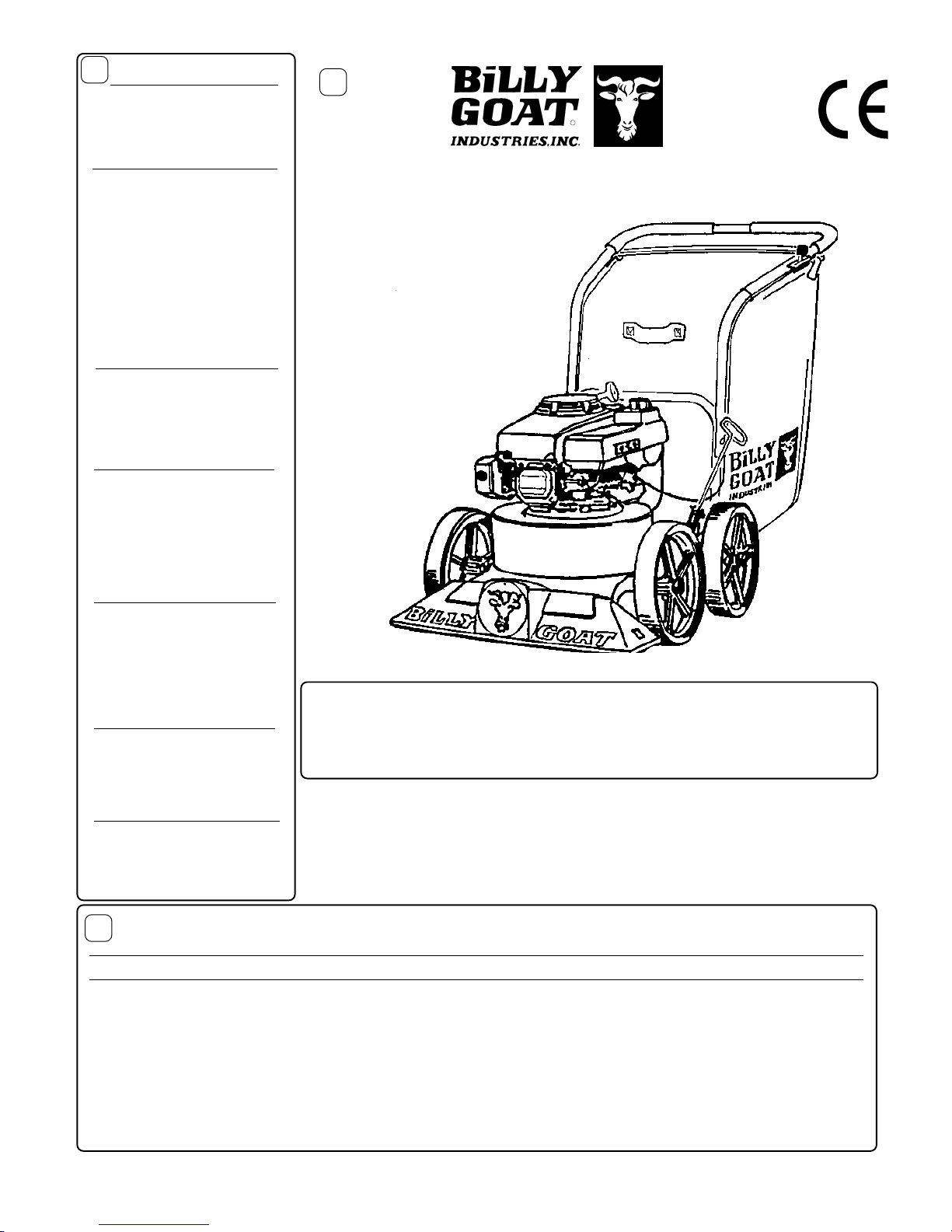
Part No. 890394 Form No. F011398B
Page 2 of 12
INTHE INTEREST OF SAFETY
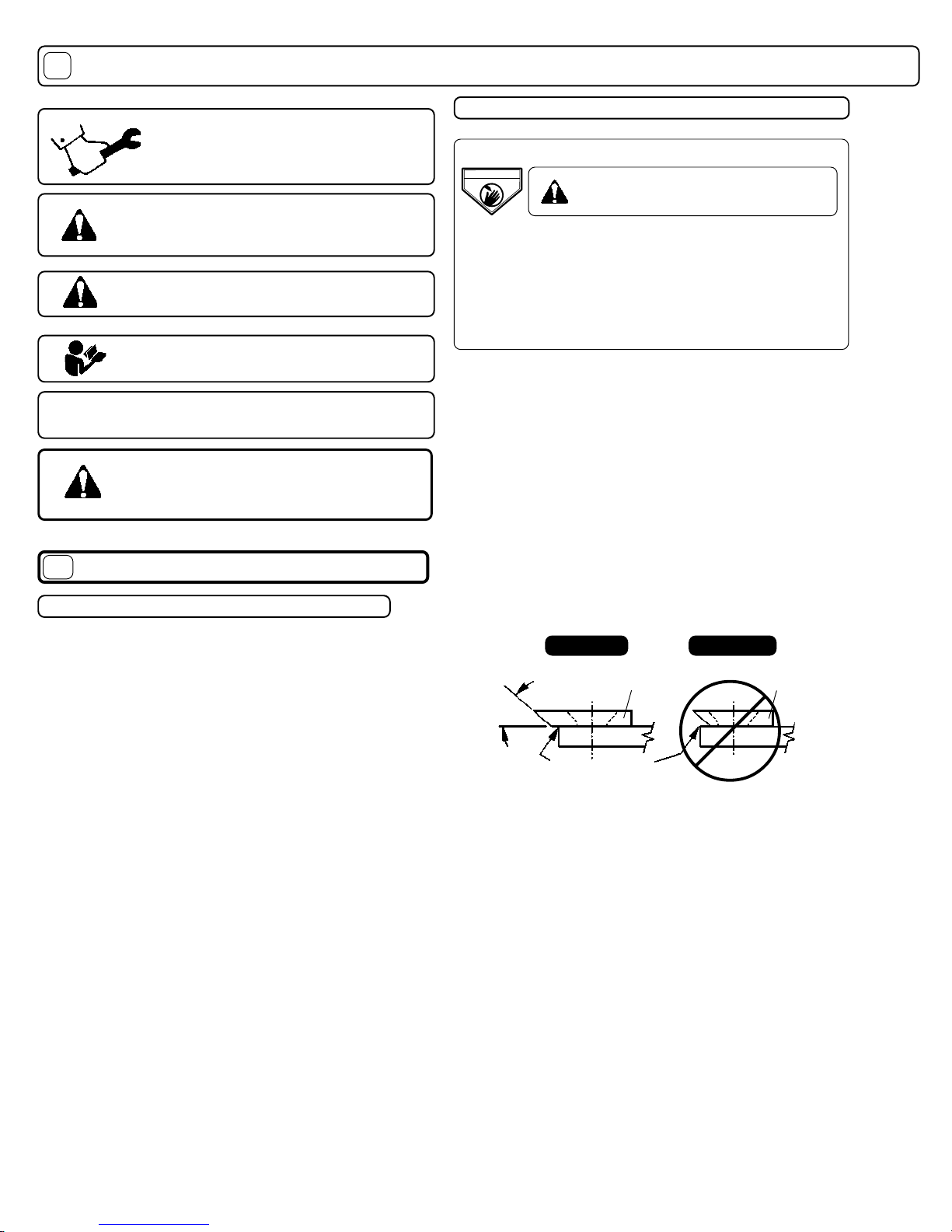
THIS SYMBOL MEANSWARNING OR CAUTION.DEATH,PERSONAL INJURY AND/OR PROPERTY
DAMAGE MAY OCCUR UNLESS INSTRUCTIONS ARE FOLLOWED CAREFULLY.
BEFORE STARTING ENGINE,READ AND UNDERSTANDTHE“ENTIRE OPERATOR'S MANUAL & EN-
GINEMANUAL.”
WARNING: DO NOT
1. DO NOT run engine in an enclosed area.
Exhaust gases contain carbon monoxide, an
odorless and deadly poison.
2. DO NOT place hands or feet near moving
or rotating parts.
3. DO NOT store, spill or use gasoline near
an open flame, or devices such as a stove,
furnace, or water heater which use a pilot
light or devices which can create a spark.
4. DO NOT refuel indoors where area is not
well ventilated. Outdoor refueling is
recommended.
5. DO NOT fill fuel tank while engine is
running. Allow engine to cool for 2 minutes
before refueling. Store fuel in approved
safety containers.
6. DO NOT remove fuel tank cap while
engine is running.
7. DO NOT operate engine when smell of
gasoline is present or other explosive
conditions exist.
8. DO NOT operate engine if gasoline is
spilled. Move machine away from the spill
and avoid creating any ignition until the
gasoline has evaporated.
9. DO NOT transport unit with fuel in tank.
10. DO NOT smoke when filling fuel tank.
11. DO NOT choke carburetor to stop
engine. Whenever possible, gradually
reduce engine speed before stopping.
12. DO NOT run engine at excessive
speeds. This may result in injury & /or
damage to unit.
13. DO NOT tamper with governor springs,
governor links or other parts which may
change the governed engine speed.
14. DO NOT tamper with the engine speed
selected by the engine manufacturer.
15. DO NOT check for spark with spark
plug or spark plug wire removed. Use an
approved tester.
16. DO NOT crank engine with spark plug
removed. If engine is flooded, place
throttle in “FAST” position and crank until
engine starts.
17. DO NOT strike flywheel with a hard
object or metal tool as this may cause
flywheel to shatter in operation. Use
proper tools to service engine.
18. DO NOT operate engine without a
muffler. Inspect periodically and replace, if
necessary. If engine is equipped with
muffler deflector, inspect periodically and
replace, if necessary, with correct deflector.
19. DO NOT operate engine with an
accumulation of grass, leaves, dirt or other
combustible material in the muffler area.
20. DO NOT use this engine on any forest
covered, brush covered, or grass covered
unimproved land unless a spark arrester is
installed on the muffler. The arrester must
be maintained in effective working order by
the operator. In the State of California the
above is required by law (Section 4442 of
the California Public Resources Code).
Other states may have similar laws.
Federal laws apply on federal lands.
OPERATOR
21. DO NOT touch hot muffler, cylinder, or
fins because contact may cause burns.
22. DO NOT run engine without air cleaner
or air cleaner cover.
23. DO NOT operate during excessive
vibration!
24. DO NOT leave machine unattended
while in operation.
25. DO NOT park machine on a steep
grade or slope.
WARNING: DO
1. ALWAYS DO remove the wire from the
spark plug when servicing the engine or
equipment TO PREVENT ACCIDENTAL
STARTING.
2. DO keep cylinder fins and governor
parts free of grass and other debris
which can affect engine speed.
3. DO pull starter cord slowly until resis-
tance is felt. Then pull cord rapidly to avoid
kickback and prevent hand or arm
injury.
4. DO examine muffler periodically to be
sure it is functioning effectively. A worn or
leaking muffler should be repaired or
replaced as necessary.
5. DO use fresh gasoline. Stale fuel can
gum carburetor and cause leakage.
6. DO check fuel lines and fittings fre-
quently for cracks or leaks. Replace if
necessary
7. Follow engine manufacturer operating
and maintenance instructions.
8. Inspect machine and work area before
starting unit.
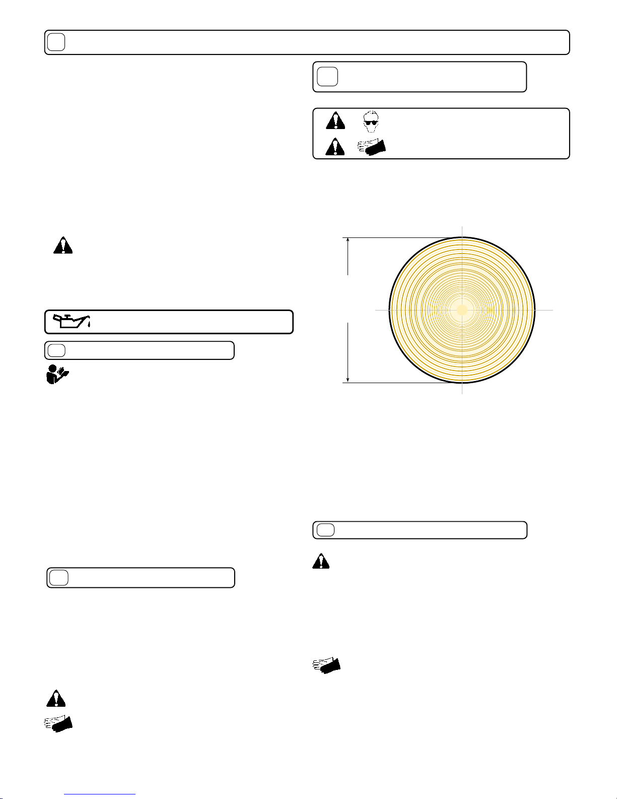
VIBRATION
SOUND TESTS VIBRATION LEVELS 1.5g
Vibration levels at the operators handles were
measured in the vertical, lateral, and longitudinal
directions using calibrated vibration test equipment.
Tests were performed on 05/19/95 under the conditions
listed:
WIND DIRECTION:
HUMIDITY:
TEMPERATURE:
BAROMETRIC PRESSURE:
GENERAL CONDI-
TION:
SOUND
Sound tests conducted were in accordance
with 79/113/EEC and were performed on 05/
22/95 under the conditions listed:
GENERAL CONDI-
TION:
L
A
p
108
WIND SPEED:
WIND DIRECTION:
HUMIDITY:
TEMPERATURE:
BAROMETRIC PRESSURE:
98
L
A
30.02"Hg (763mm Hg)
71 %
S.E.
10MPH (16.1 kmh)
72 F (22.2 C)
Sunny
30.06"Hg (764mm Hg)
67 %
South
5 MPH (8.0 kmh)
62 F (16.7 C)
Sunny
55
55
5
6
8
7
○○○○○○
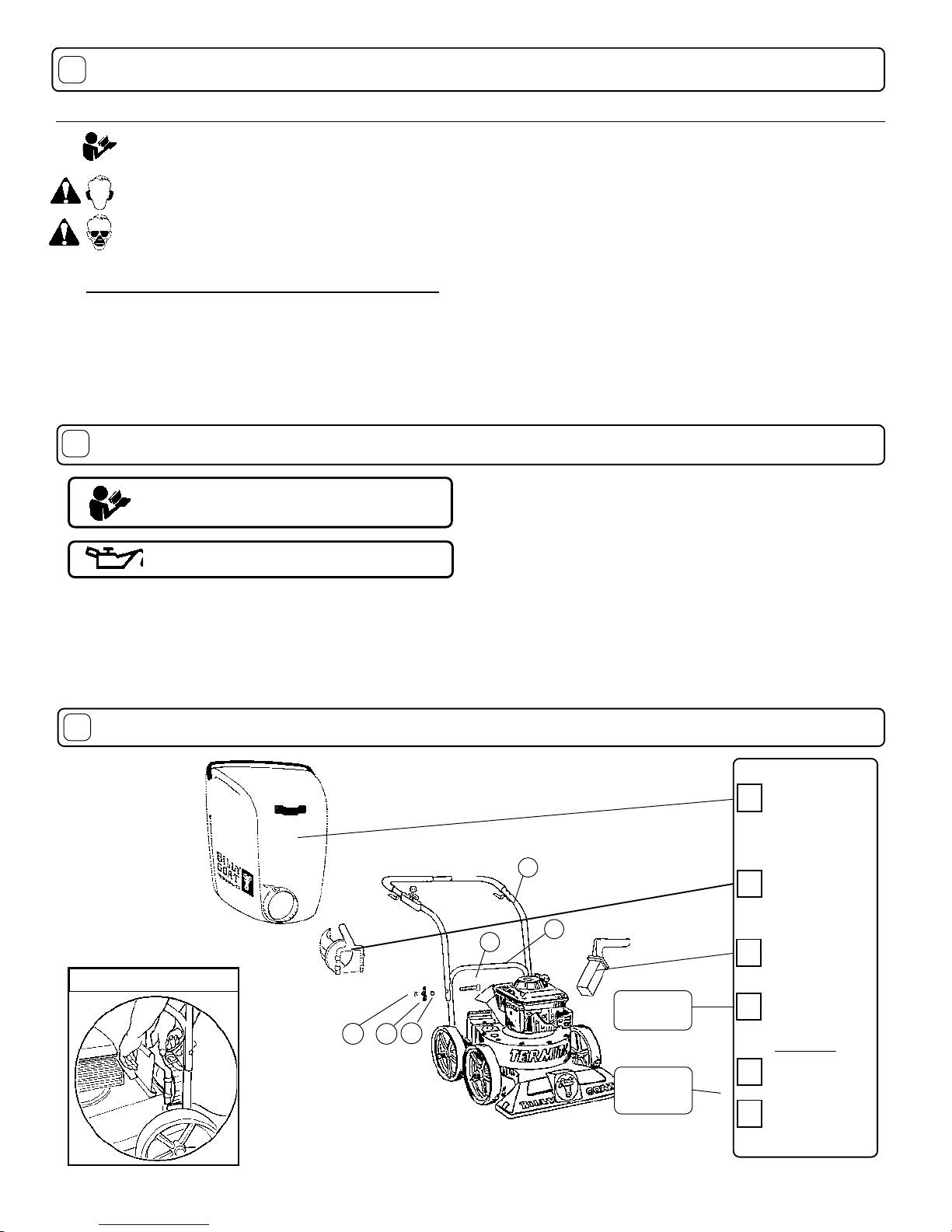
SAFETYINSTRUCTIONS
GENERAL SAFETY
ASSEMBLY
PARTS BAG & CONTROLS
LABELS
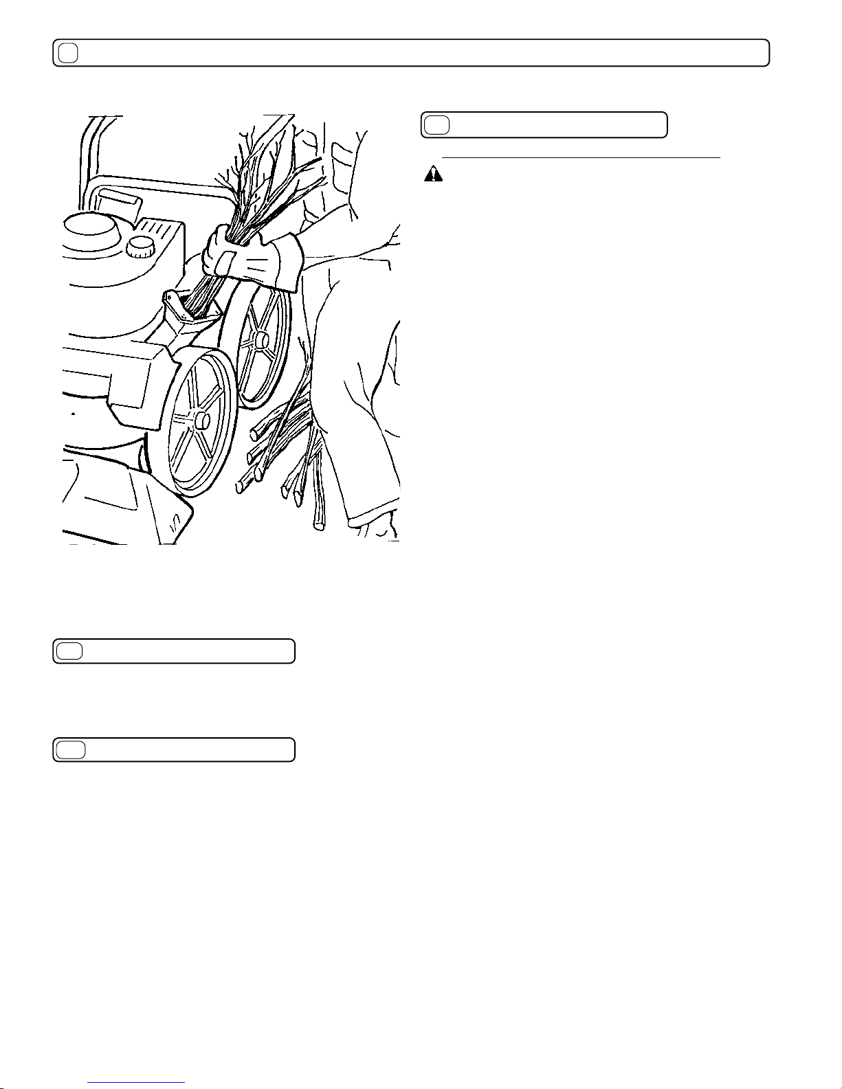
OPERATION
MAINTENANCE
PARTS DRAWING & LIST
TROUBLESHOOTING
WARRANTY PROCEDURE
○○○
○○ ○○○○○
○○○○○○○○
○○○○○○○○
○○○○○
○○
8 - 9
12
12
5 - 7
4
4
3
3
2
TABLE OF CONTENTS
10 -
12
WARNING: The Engine Exhaust from this product contains chemicals known
to the State of California to cause cancer, birth defects or other reproductive harm.