Part No. 890252 Form No. F021795B
Page 2 of 12
ININ
ININ
IN THE INTEREST OF SAFETYTHE INTEREST OF SAFETY
THE INTEREST OF SAFETYTHE INTEREST OF SAFETY
THE INTEREST OF SAFETY
THIS SYMBOL MEANSTHIS SYMBOL MEANS
THIS SYMBOL MEANSTHIS SYMBOL MEANS
THIS SYMBOL MEANS WW
WW
WARNING OR CAARNING OR CA
ARNING OR CAARNING OR CA
ARNING OR CAUTION.UTION.
UTION.UTION.
UTION. DEADEA
DEADEA
DEATH,TH,
TH,TH,
TH, PERSONAL INJURPERSONAL INJUR
PERSONAL INJURPERSONAL INJUR
PERSONAL INJURY AND/OR PRY AND/OR PR
Y AND/OR PRY AND/OR PR
Y AND/OR PROPEROPER
OPEROPER
OPERTYTY
TYTY
TY
DD
DD
DAMAAMA
AMAAMA
AMA
GE MAGE MA
GE MAGE MA
GE MAY OCCUR UNLESS INSTRY OCCUR UNLESS INSTR
Y OCCUR UNLESS INSTRY OCCUR UNLESS INSTR
Y OCCUR UNLESS INSTRUCTIONS ARE FOLLOUCTIONS ARE FOLLO
UCTIONS ARE FOLLOUCTIONS ARE FOLLO
UCTIONS ARE FOLLOWED CAREFULLWED CAREFULL
WED CAREFULLWED CAREFULL
WED CAREFULLYY
YY
Y..
..
.
BEFORE STBEFORE ST
BEFORE STBEFORE ST
BEFORE STARAR
ARAR
AR
TING ENGINE,TING ENGINE,
TING ENGINE,TING ENGINE,
TING ENGINE, READ AND UNDERSTREAD AND UNDERST
READ AND UNDERSTREAD AND UNDERST
READ AND UNDERSTANDAND
ANDAND
AND
THETHE
THETHE
THE “ENTIRE OPERA“ENTIRE OPERA
“ENTIRE OPERA“ENTIRE OPERA
“ENTIRE OPERATT
TT
TOR'S MANUOR'S MANU
OR'S MANUOR'S MANU
OR'S MANUAL & EN-AL & EN-
AL & EN-AL & EN-
AL & EN-
GINE MANUGINE MANU
GINE MANUGINE MANU
GINE MANUAL.AL.
AL.AL.
AL.””
””
”
WW
WW
WARNING:ARNING:
ARNING:ARNING:
ARNING: DO NODO NO
DO NODO NO
DO NOTT
TT
T
1. DO NOTDO NOT
DO NOTDO NOT
D O N O T run engine in an enclosed area.
Exhaust gases contain carbon monoxide,
an odorless and deadly poison.
2. DO NOTDO NOT
DO NOTDO NOT
D O N O T place hands or feet near moving
or rotating parts.
3. DO NOTDO NOT
DO NOTDO NOT
D O N O T store, spill or use gasoline near
an open flame, or devices such as a stove,
furnace, or water heater which use a pilot
light or devices which can create a spark.
4. DO NOTDO NOT
DO NOTDO NOT
D O N O T refuel indoors where area is not
well ventilated. Outdoor refueling is
recommended.
5. DO NOTDO NOT
DO NOTDO NOT
D O N O T fill fuel tank while engine is
running. Allow engine to cool for 2 minutes
before refueling. Store fuel in approved
safety containers.
6. DO NOTDO NOT
DO NOTDO NOT
D O N O T remove fuel tank cap while
engine is running.
7. DO NOTDO NOT
DO NOTDO NOT
DO NOT operate engine when smell of
gasoline is present or other explosive
conditions exist.
8. DO NOTDO NOT
DO NOTDO NOT
D O N O T operate engine if gasoline is
spilled. Move machine away from the spill
and avoid creating any ignition until the
gasoline has evaporated.
9. DO NOTDO NOT
DO NOTDO NOT
D O N O T transport unit with fuel in tank.
10. DO NOTDO NOT
DO NOTDO NOT
D O N O T smoke when filling fuel tank.
11. DO NOTDO NOT
DO NOTDO NOT
D O N O T choke carburetor to stop
engine. Whenever possible, gradually
reduce engine speed before stopping.
12. DO NOTDO NOT
DO NOTDO NOT
DO NOT run engine at excessive
speeds. This may resultininjur y & /or
damage to unit.
13. DO NOTDO NOT
DO NOTDO NOT
D O N O T tamper with governor springs,
governor links or other parts which may
change the governed engine speed.
14. DO NOTDO NOT
DO NOTDO NOT
D O N O T tamper with the engine speed
selected by the engine manuf acturer.
15. DO NOTDO NOT
DO NOTDO NOT
D O N O T check for spark with spark
plug or spark plug wire removed. Use an
approved tester.
16. DO NOTDO NOT
DO NOTDO NOT
D O N O T crank engine with spark plug
removed. If engine is flooded, place
throttlein“FAST” position and crank until
engine starts.
17. DO NODO NO
DO NODO NO
D O N O T strike flywheel with a hard
object or metal tool as this may cause
flywheel to shatter in operation. Use
proper tools to service engine.
18. DO NOTDO NOT
DO NOTDO NOT
D O N O T operate engine without a
muffler. Inspect per iodically and replace,if
necessary. If engine is equipped with
m uffler deflector , inspect per iodically and
replace , if necessar y, with correct deflector.
19. DO NOTDO NOT
DO NOTDO NOT
D O N O T operate engine with an
accumulation of grass, leaves, dirt or other
combustible material in the muffler area.
20. DO NOTDO NOT
DO NOTDO NOT
D O N O T use this engine on any forest
covered, brush covered, or grass covered
unimproved land unless a spark arrester is
installed on the muffler.The arrester must
be maintained in effective working order by
the operator . In the State of Calif or nia the
above is required by law (Section 4442 of
the California Public Resources Code).
Other states may have similar laws.
Federal laws apply on federal lands.
OPERATO R
21. DO NODO NO
DO NODO NO
D O N OT touch hot muffler , cylinder , or
fins because contact may cause burns.
22. DO NOTDO NOT
DO NOTDO NOT
D O N O T run engine without air cleaner
or air cleaner co ver.
23. DO NOTDO NOT
DO NOTDO NOT
D O N O T operate during excessive
vibration!
24. DO NOTDO NOT
DO NOTDO NOT
D O N O T leave machine unattended
while in operation.
25. DO NOTDO NOT
DO NOTDO NOT
D O N O T park machine on a steep
grade or slope.
WW
WW
WARNING:ARNING:
ARNING:ARNING:
ARNING: DODO
DODO
DO
1.
ALAL
ALAL
AL
WW
WW
WAA
AA
AYS DOYS DO
YS DOYS DO
Y S D O remove the wire from the
spark plug when servicing the engine or
equipment TO PREVENT ACCIDENTAL
STA RTING.
2. DODO
DODO
D O keep cylinder fins and governor
parts free of grass and other debris
which can affect engine speed.
3. DODO
DODO
D O pull starter cord slowly until resis-
tance is f elt. Then pull cord rapidly to a void
kickback and prevent hand or arm
injury.
4. DODO
DODO
D O examine muffler periodically to be
sure it is functioning eff ectiv ely. A worn or
leaking muffler should be repaired or
replaced as necessar y.
5. DODO
DODO
D O use fresh gasoline. Stale fuel can
gum carburetor and cause leakage.
6. DODO
DODO
D O check fuel lines and fittings fre-
quently for cracks or leaks. Replace if
necessary
7. FollowFollow
FollowFollow
Follow engine manufacturer operating
and maintenance instructions.
8. InspectInspect
InspectInspect
Inspect machine and work area before
starting unit.
VIBRAVIBRA
VIBRAVIBRA
VIBRATIONTION
TIONTION
TION
SOUND TESTS VIBRATION LEVELS 2.7g
Vibration levels at the operators handles were
measured in the vertical, lateral, and longitudinal
directions using calibrated vibration test equipment.
Tests were perf or med on 05/20/94 under the conditions
listed:
WIND SPEED:
WIND DIRECTION:
HUMIDITY:
TEMPERATURE:
BAROMETRIC PRESSURE:
GENERAL CONDI-
TION:
SOUNDSOUND
SOUNDSOUND
SOUND
Sound tests conducted were in accordance
with 79/113/EEC and were performed on 05/
20/94 under the conditions listed:
GENERAL CONDI-
TION:
L
A
p
109
WIND SPEED:
WIND DIRECTION:
HUMIDITY:
TEMPERATURE:
BAROMETRIC PRESSURE:
97
L
A
30.1" Hg (765mm Hg)
58%
N.W.
3 MPH (4.8 kmh)
Sunny
30.1" Hg (765mm Hg)
58 %
N.W.
3 MPH (4.8 kmh)
70 F (21.1 C)
Sunny
55
55
5
66
66
6
88
88
8
77
77
7
○○○○○○
SAFETY INSTRUCTIONSSAFETY INSTRUCTIONS
SAFETY INSTRUCTIONSSAFETY INSTRUCTIONS
SAFETY INSTRUCTIONS
GENERAL SAFETYGENERAL SAFETY
GENERAL SAFETYGENERAL SAFETY
GENERAL SAFETY
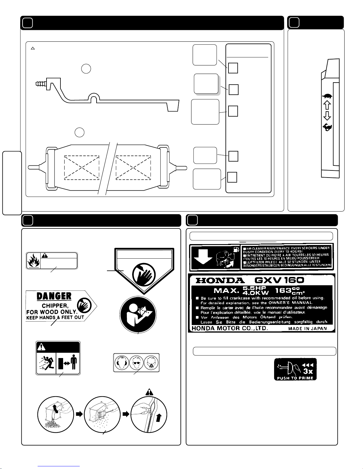
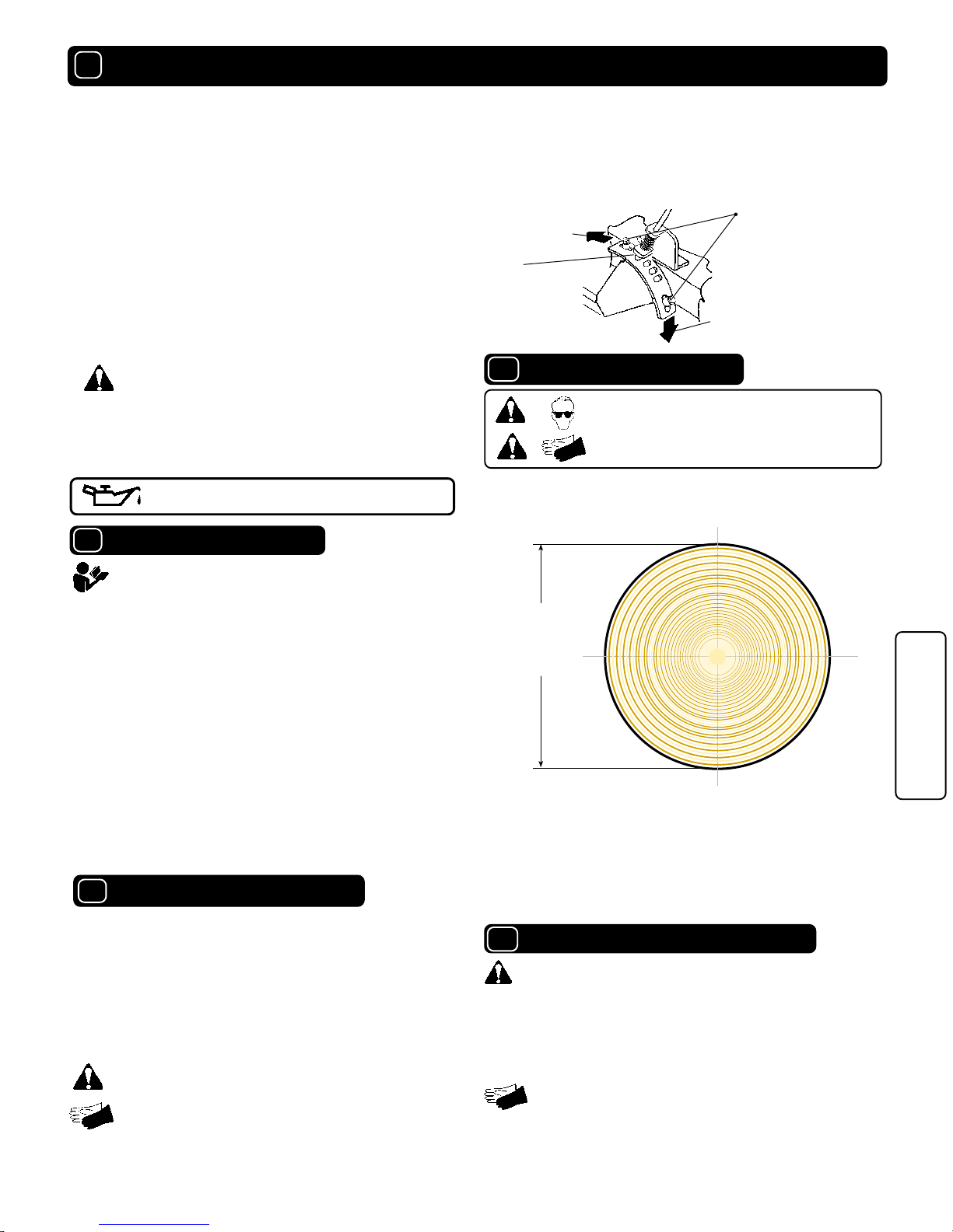
ASSEMBLASSEMBL
ASSEMBLASSEMBL
ASSEMBL
YY
YY
Y
PP
PP
PARAR
ARAR
AR
TS BTS B
TS BTS B
TS BAA
AA
AG & CONTRG & CONTR
G & CONTRG & CONTR
G & CONTROLSOLS
OLSOLS
OLS
LABELSLABELS
LABELSLABELS
LABELS
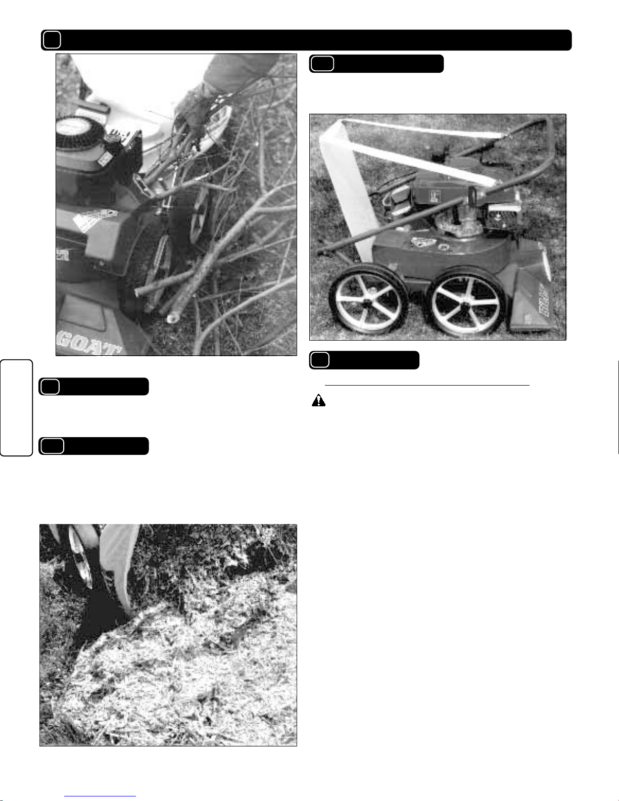
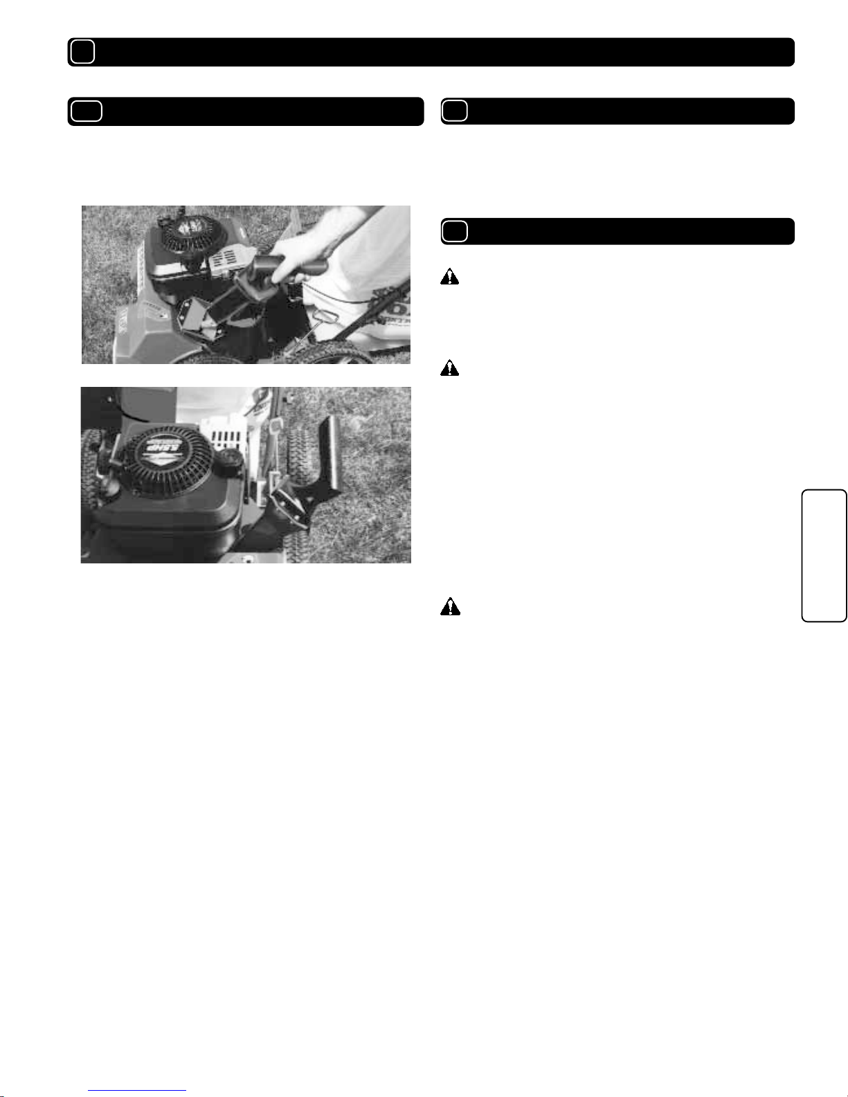
OPERAOPERA
OPERAOPERA
OPERA
TIONTION
TIONTION
TION
MAINTENANCEMAINTENANCE
MAINTENANCEMAINTENANCE
MAINTENANCE
PP
PP
PARAR
ARAR
AR
TS DRATS DRA
TS DRATS DRA
TS DRAWING & LISTWING & LIST
WING & LISTWING & LIST
WING & LIST
TROUBLESHOOTINGTROUBLESHOOTING
TROUBLESHOOTINGTROUBLESHOOTING
TROUBLESHOOTING
WW
WW
WARRANTY PRARRANTY PR
ARRANTY PRARRANTY PR
ARRANTY PROCEDUREOCEDURE
OCEDUREOCEDURE
OCEDURE
○○○
○○ ○○○○○
○○○○○○○○
○○○○○○○○
○○○○○
○○
8 - 9
12
12
5 - 7
4
4
3
3
2
TT
TT
TABLE OF CONTENTSABLE OF CONTENTS
ABLE OF CONTENTSABLE OF CONTENTS
ABLE OF CONTENTS
10 - 12
WARNING: The Engine Exhaust from this product contains chemicals known
to the State of California to cause cancer, birth defects or other reproductive harm.
SAFETY 2