Part No. 890207 Form No. F021795E
SAFETY 2
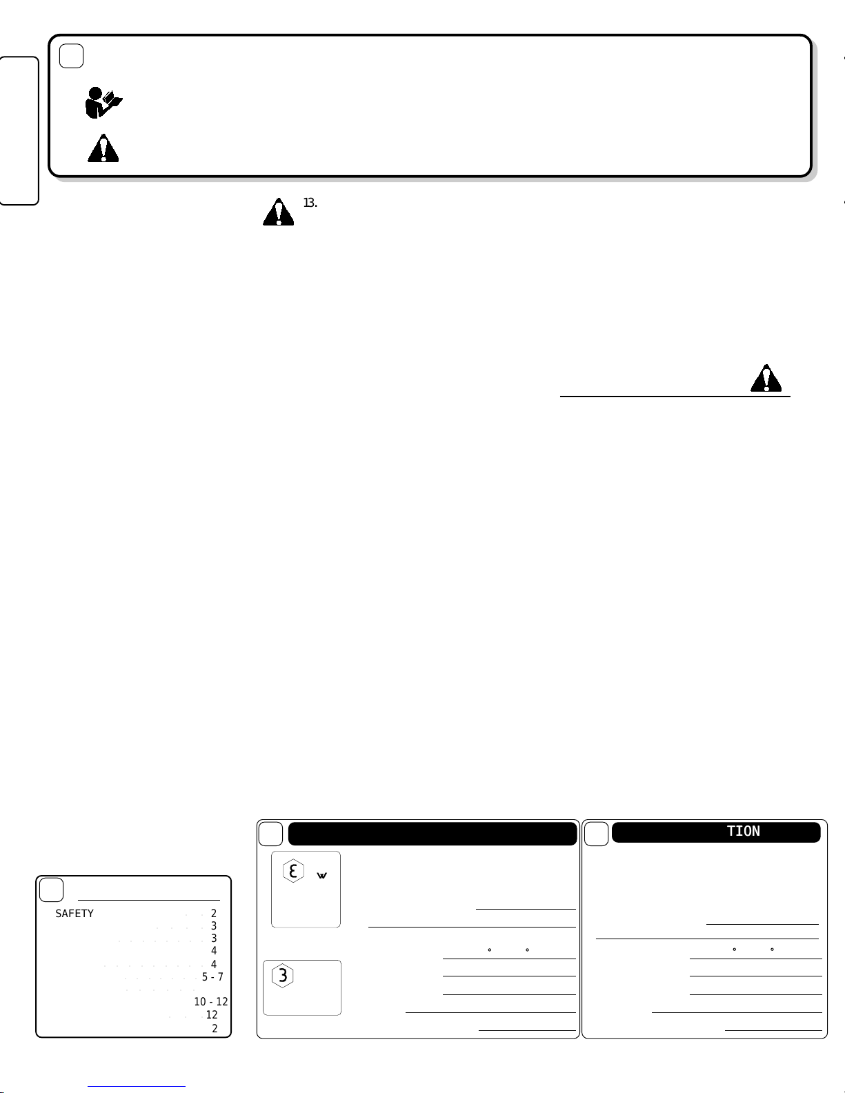
THIS SYMBOL MEANSTHIS SYMBOL MEANS
THIS SYMBOL MEANSTHIS SYMBOL MEANS
THIS SYMBOL MEANS WW
WW
WARNING OR CAARNING OR CA
ARNING OR CAARNING OR CA
ARNING OR CAUTION.UTION.
UTION.UTION.
UTION. DEADEA
DEADEA
DEATH,TH,
TH,TH,
TH, PERSONAL INJURPERSONAL INJUR
PERSONAL INJURPERSONAL INJUR
PERSONAL INJURY AND/OR PRY AND/OR PR
Y AND/OR PRY AND/OR PR
Y AND/OR PROPEROPER
OPEROPER
OPERTYTY
TYTY
TY
DD
DD
DAMAAMA
AMAAMA
AMA
GE MAGE MA
GE MAGE MA
GE MAY OCCUR UNLESS INSTRY OCCUR UNLESS INSTR
Y OCCUR UNLESS INSTRY OCCUR UNLESS INSTR
Y OCCUR UNLESS INSTRUCTIONS ARE FOLLOUCTIONS ARE FOLLO
UCTIONS ARE FOLLOUCTIONS ARE FOLLO
UCTIONS ARE FOLLOWED CAREFULLWED CAREFULL
WED CAREFULLWED CAREFULL
WED CAREFULLYY
YY
Y..
..
.
BEFORE STBEFORE ST
BEFORE STBEFORE ST
BEFORE STARAR
ARAR
AR
TING ENGINE,TING ENGINE,
TING ENGINE,TING ENGINE,
TING ENGINE, READ AND UNDERSTREAD AND UNDERST
READ AND UNDERSTREAD AND UNDERST
READ AND UNDERSTANDAND
ANDAND
AND THETHE
THETHE
THE “ENTIRE OPERA“ENTIRE OPERA
“ENTIRE OPERA“ENTIRE OPERA
“ENTIRE OPERATT
TT
TOR'S MANUOR'S MANU
OR'S MANUOR'S MANU
OR'S MANUAL &AL &
AL &AL &
AL &
ENGINE MANUENGINE MANU
ENGINE MANUENGINE MANU
ENGINE MANUAL.AL.
AL.AL.
AL.””
””
”
WW
WW
WARNING:ARNING:
ARNING:ARNING:
ARNING: DO NODO NO
DO NODO NO
DO NOTT
TT
T
1.
DO NODO NO
DO NODO NO
DO NOTT
TT
Tr un engine in an enclosed area.
Exhaust gases contain carbon monoxide, an
odorless and deadly poison.
2.
DO NODO NO
DO NODO NO
DO NOTT
TT
T place hands or feet near moving
or rotating par ts.
3.
DO NODO NO
DO NODO NO
DO NOTT
TT
T store , spill or use gasoline near
an open flame, or devices such as a stove,
furnace, or water heater which use a pilot
light or devices which can create a spar k.
4.
DO NODO NO
DO NODO NO
DO NOTT
TT
T refuel indoors where area is not
wellv entilated. Outdoor refueling is recom-
mended.
5.
DO NODO NO
DO NODO NO
DO NOTT
TT
T fill fuel tank while engine is
running. Allow engine to cool f or 2 minutes
before refueling. Store fuel in approved
safety containers.
6.
DO NODO NO
DO NODO NO
DO NOTT
TT
T remove fuel tank cap while
engine is r unning.
7.
DO NODO NO
DO NODO NO
DO NOTT
TT
Toperate engine when smell of
gasoline is present or other explosiv e
conditions exist.
8.
DO NODO NO
DO NODO NO
DO NOTT
TT
T oper ate engine if gasoline is
spilled. Mo ve machine aw ay from the spill
and avoid creating any ignition until the
gasoline has evaporated.
9.
DO NODO NO
DO NODO NO
DO NOTT
TT
Ttransport unit with fuel in tank.
10. DO NODO NO
DO NODO NO
DO NOTT
TT
T smoke when filling fuel tank.
11. DO NODO NO
DO NODO NO
DO NOTT
TT
T choke carburetor to stop engine .
Whenever possible,gradually reduce engine
speed before stopping.
12. DO NODO NO
DO NODO NO
DO NOTT
TT
Trun engine at excessive
speeds. This may result in injur y & /or
damage to unit.
○○○○○○
SAFETY INSTRSAFETY INSTR
SAFETY INSTRSAFETY INSTR
SAFETY INSTRUCTIONSUCTIONS
UCTIONSUCTIONS
UCTIONS
GENERAL SAFETYGENERAL SAFETY
GENERAL SAFETYGENERAL SAFETY
GENERAL SAFETY
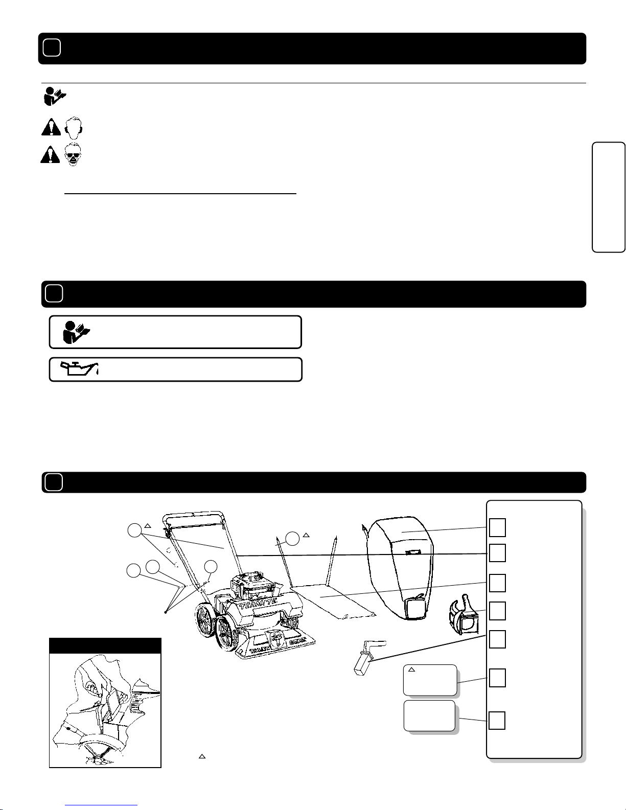
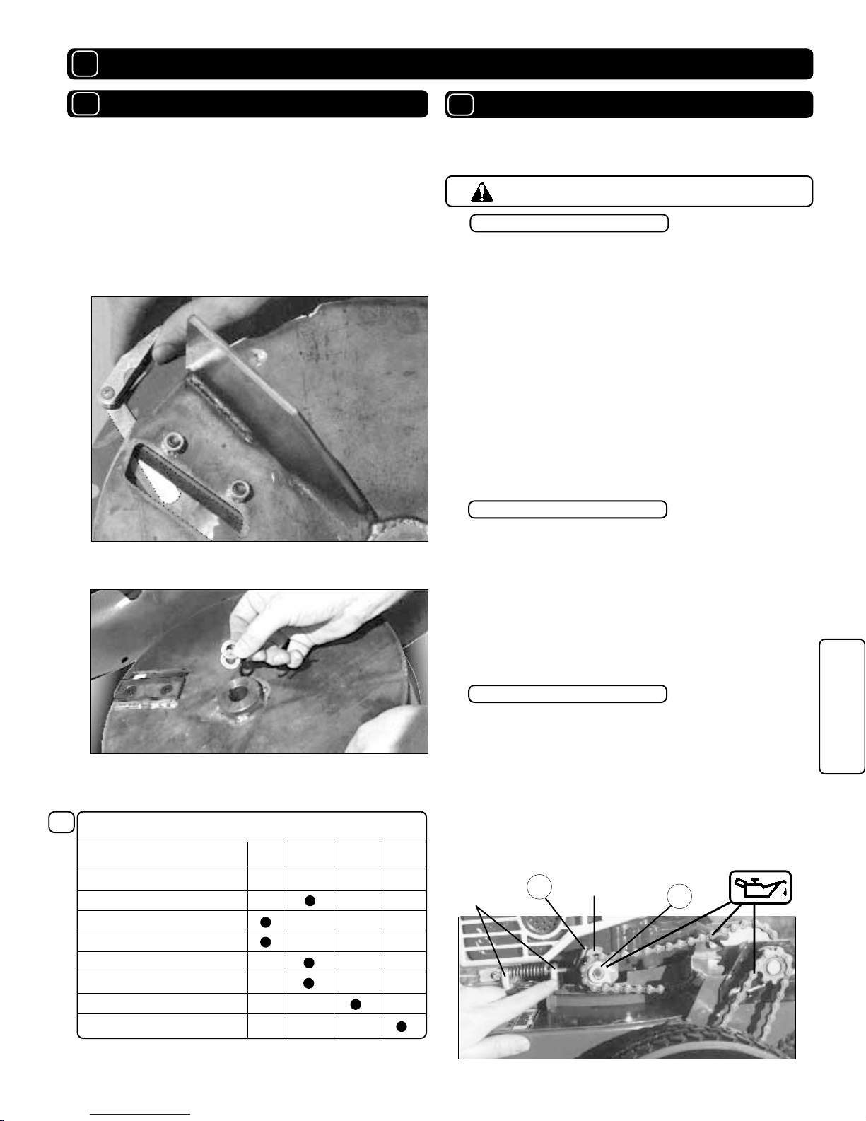
ASSEMBLASSEMBL
ASSEMBLASSEMBL
ASSEMBL
YY
YY
Y
PP
PP
PARAR
ARAR
AR
TS BTS B
TS BTS B
TS BAA
AA
AG & CONTRG & CONTR
G & CONTRG & CONTR
G & CONTROLSOLS
OLSOLS
OLS
LABELSLABELS
LABELSLABELS
LABELS
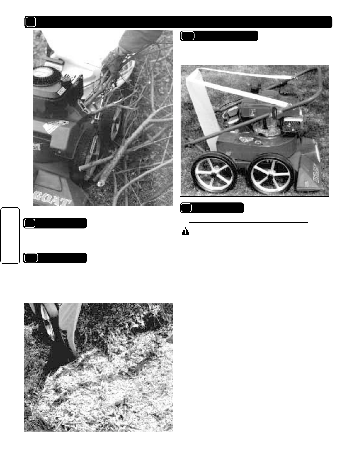
OPERAOPERA
OPERAOPERA
OPERA
TIONTION
TIONTION
TION
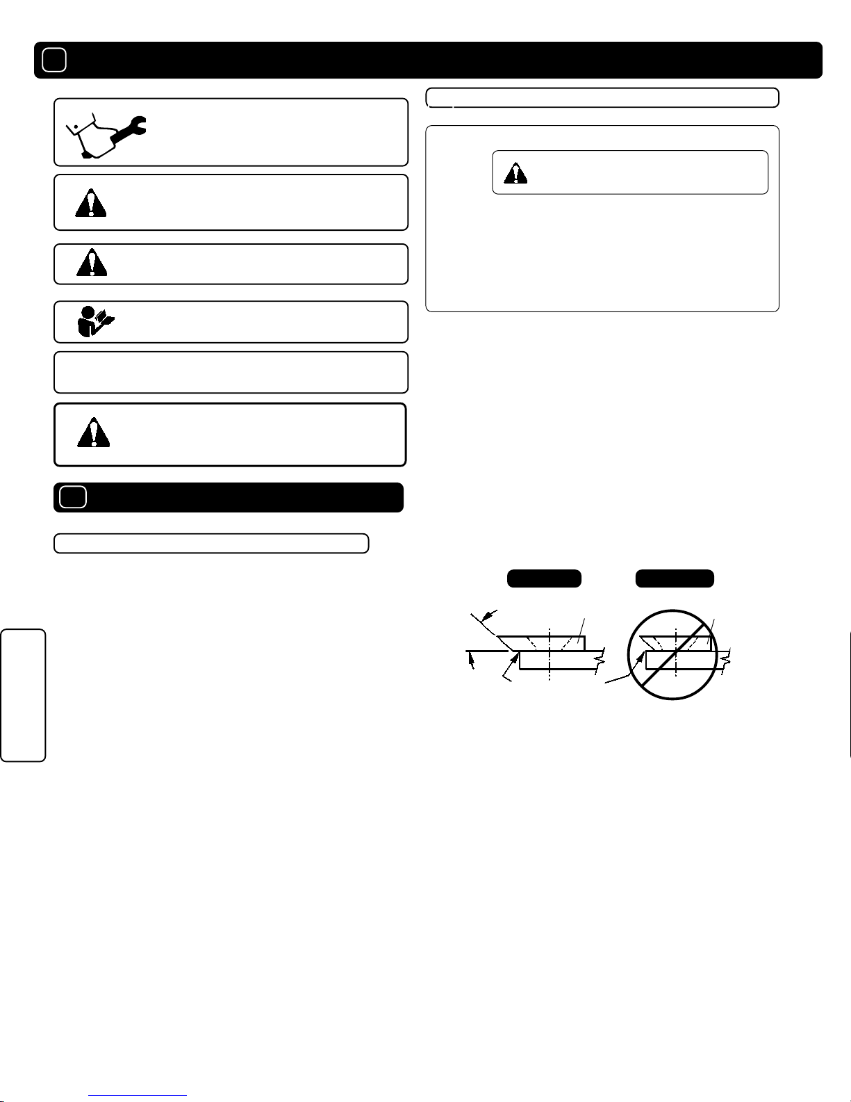
MAINTENANCEMAINTENANCE
MAINTENANCEMAINTENANCE
MAINTENANCE
PP
PP
PARAR
ARAR
AR
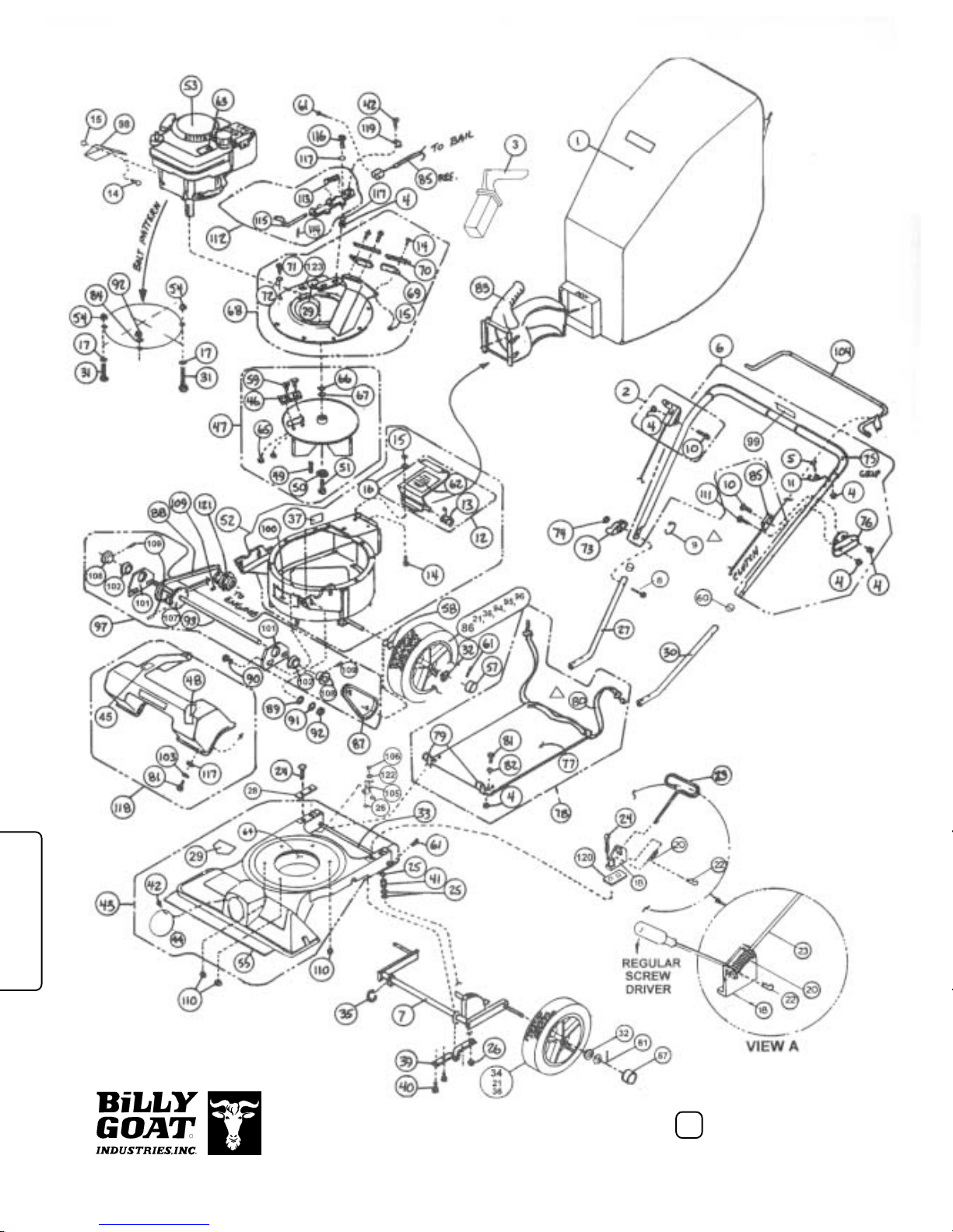
TS DRATS DRA
TS DRATS DRA
TS DRAWING & LISTWING & LIST
WING & LISTWING & LIST
WING & LIST
TRTR
TRTR
TROUBLESHOOOUBLESHOO
OUBLESHOOOUBLESHOO
OUBLESHOOTINGTING
TINGTING
TING
WW
WW
WARRANTY PRARRANTY PR
ARRANTY PRARRANTY PR
ARRANTY PROCEDUREOCEDURE
OCEDUREOCEDURE
OCEDURE
○○○
○○ ○○○○○
○○○○○○○○
○○○○
○○
8 - 9
12
12
10 - 12
5 - 7
4
4
3
3
2
13. DO NODO NO
DO NODO NO
DO NOTT
TT
T tamper with gover nor spr ings ,
gover nor links or other par ts which may
change the governed engine speed.
14. DO NODO NO
DO NODO NO
DO NOTT
TT
T tamper with the engine speed
selected by the engine manufacturer.
15. DO NODO NO
DO NODO NO
DO NOTT
TT
T checkf or spar k with spark plug
or spar k plug wire removed. Use an
approved tester .
16. DO NODO NO
DO NODO NO
DO NOTT
TT
T cr ank engine with spar k plug
removed. If engine is flooded, place throttle
in “FAST” position and crank until engine
star ts.
17. DO NODO NO
DO NODO NO
DO NOTstr ik e flywheel with a hard
object or metal tool as this may cause
flywheel to shatter in oper ation. Use proper
tools to ser vice engine.
18. DO NODO NO
DO NODO NO
DO NOTT
TT
T operate engine without a
muffler. Inspect per iodically and replace ,if
necessary. If engine is equipped with
m uffler deflector , inspect per iodically and
replace, if necessar y, with correct deflector.
19. DO NODO NO
DO NODO NO
DO NOTT
TT
T operate engine with an
accumulation of g rass, leaves,dir t or other
combustib le mater ial in the m uffler area.
20. DO NODO NO
DO NODO NO
DO NOTT
TT
T use this engine on anyf orest
co vered, br ush covered, or g rass covered
unimproved land unless a spar k arrester is
installed on the m uffler.The arrester must
be maintained in effectiv e w or king order by
the operator . In the State of Calif or nia the
abo ve is required b y law (Section 4442 of
the Calif or nia Public Resources Code).
Other states may have similar la w s . Federal
laws apply on federal lands.
OPERATO R
21. DO NODO NO
DO NODO NO
D O N OT touch hot muffler , cylinder , or
fins because contact may cause burns.
22. DO NODO NO
DO NODO NO
DO NOTT
TT
Tr un engine without air cleaner
or air cleaner cover.
23. DO NODO NO
DO NODO NO
DO NOTT
TT
T oper ate dur ing e xcessiv e
vibr ation!
24. DO NODO NO
DO NODO NO
DO NOTT
TT
T leave machine unattended
while in oper ation.
25. DO NODO NO
DO NODO NO
DO NOTT
TT
T par k machine on a steep grade
or slope .
WW
WW
WARNING:ARNING:
ARNING:ARNING:
ARNING: DODO
DODO
DO
1.
ALAL
ALAL
AL
WW
WW
WAA
AA
AYS DOYS DO
YS DOYS DO
Y S D O remove the wire from the
spark plug when ser vicing the engine or
equipment TO PREVENT ACCIDENTAL
STA RTING.
2.
DODO
DODO
DOkeep cylinder fins and go ver nor
par ts free of g rass and other debr is
which can affect engine speed.
3.
DODO
DODO
D O pull star ter cord slo wly until resis-
tance is f elt. Then pull cord r apidly to a void
kickback and prevent hand or ar m injur y.
4.
DODO
DODO
DOexamine muffler per iodically to be
sure it is functioning eff ectiv ely.A wornor
leaking muffler should be repaired or
replaced as necessary.
5.
DODO
DODO
D O use fresh gasoline . Stale fuel can
gum carburetor and cause leakage.
6.
DODO
DODO
D O check fuel lines and fittings frequently
for cr acks or leaks. Replace if necessar y
7.
FolloFollo
FolloFollo
Followw
ww
w engine manufacturer oper ating
and maintenance instructions.
8.
InspectInspect
InspectInspect
Inspect machine and wor k area bef ore
star ting unit.
SOUND TESTS VIBRATION LEVEL 2.7g
Vibration le vels at the oper ators handles were
measured in the vertical,later al, and longitudinal
directions using calibr ated vibr ation test equipment.
Tests w ere perf ormed on 05/20/94 under the
conditions listed:
WIND SPEED:
WIND DIRECTION:
HUMIDITY:
TEMPERATURE:
BAROMETRIC PRESSURE:
GENERAL CONDITION:
SOUNDSOUND
SOUNDSOUND
SOUND
Sound tests conducted were in accordance
with 79/113/EEC and were perf ormed on 05/20/
94 under the conditions listed:
GENERAL CONDITION:
L
A
p
109
30.1" Hg (765mm Hg)
58 %
N.W.
3 MPH (4.8 kmh)
70 F (21.1 C)
WIND SPEED:
WIND DIRECTION:
HUMIDITY:
TEMPERATURE:
BAROMETRIC PRESSURE:
Page 2 of 12
97
L
A
Sunny
30.1" Hg (765mm Hg)
58 %
N.W.
3 MPH (4.8 kmh)
70 F (21.1 C)
Sunny
ININ
ININ
IN THE INTEREST OF SAFETYTHE INTEREST OF SAFETY
THE INTEREST OF SAFETYTHE INTEREST OF SAFETY
THE INTEREST OF SAFETY
55
55
5
66
66
6
77
77
788
88
8
TT
TT
TABLE OF CONTENTSABLE OF CONTENTS
ABLE OF CONTENTSABLE OF CONTENTS
ABLE OF CONTENTS
○○○○○○○○○
VIBRAVIBRA
VIBRAVIBRA
VIBRATIONTION
TIONTION
TION