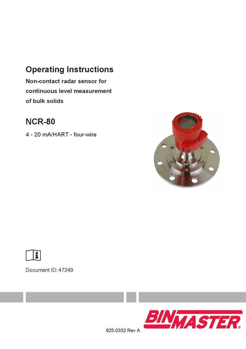
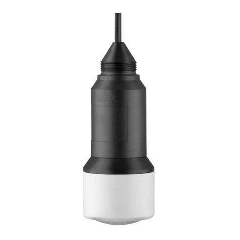
Bin Master CNCR-230 User manual

CNCR-230 • Two-wire 4
-
20 mA/HART 1
Operating Instructions
Radar sensor for continuous level measurement
CNCR-230
Two-wire 4
-
20 mA/HART
Document ID: 925-0397 Rev B

CNCR-230 • Two-wire 4
-
20 mA/HART 2
Contents
1 About this document.............................................................................................................3
2 For your safety.......................................................................................................................3
2.1 Authorized personnel ......................................................................................................3
2.2 Appropriate use ...............................................................................................................3
2.3 Warning about incorrect use............................................................................................4
3 Product description...............................................................................................................4
3.1 Conguration ...................................................................................................................4
3.2 Principle of operation.......................................................................................................5
3.3 Adjustment. .....................................................................................................................5
4 Mounting.................................................................................................................................6
4.1 General instructions........................................................................................................ 6
4.2 Mounting instructions...................................................................................................... 7
5 Connecting to power supply ..............................................................................................10
5.1 Preparing the connection ..............................................................................................10
5.2 Connection ....................................................................................................................11
5.3 Wiring plan ....................................................................................................................12
6 Set up with the integrated display and adjustment unit ..................................................12
6.1 Adjustment system ........................................................................................................12
6.2 Measured value and menu item display........................................................................14
6.3 Menu overview ..............................................................................................................15
6.4 Parameter adjustment ...................................................................................................16
7 Set up with the smartphone /tablet (Bluetooth)................................................................23
7.1 Preparations. .................................................................................................................23
7.2 Connecting ....................................................................................................................23
7.3 Parameter adjustment ...................................................................................................24
8 Diagnostics and servicing.................................................... ..............................................25
8.1 Maintenance..................................................................................................................25
8.2 Status messages...........................................................................................................25
9 Removal................................................................................................................................27
9.1 Disposal.........................................................................................................................27
10 Certicates and approvals..................................................................................................27
10.1 Radio licenses ...............................................................................................................27
11 Supplement ..........................................................................................................................27
11.1 Technical Data...............................................................................................................27

CNCR-230 • Two-wire 4
-
20 mA/HART 3
Information, note, tip: This symbol indicates helpful additional
information and tips.
Note: This symbol indicates notes to prevent failures, malfunctions,
damage to devices or facility.
Caution: Non-observance may result in personal injury.
Warning: Non-observance may result in serious or fatal personal injury.
Danger: Non-observance of the information marked with this symbol
results in serious or fatal personal injury.
Ex applications
This symbol indicates special instructions for Ex applications.
List
The dot set in front indicates a list with no implied sequence.
Sequence of actions
Numbers set in front indicate successive steps in a procedure.
Battery disposal
This symbol indicates special information about the disposal of
batteries and accumulators.
1 About this document
2 For your safety
2.1 Authorized personnel
Alloperationsdescribedinthisdocumentationmustbecarriedoutonlybytrained,qualied
personnel authorized by the plant operator. Required personal protective equipment must always
be worn when working on or with the device.
2.2 Appropriate use
CNCR-230 is a sensor for continuous level measurement.
Operational reliability is ensured only if the instrument is properly used according to the
specicationsintheoperatinginstructions.

CNCR-230 • Two-wire 4
-
20 mA/HART 4
Safety instructions for Ex areas
TakenoteoftheExspecicsafetyinstructionsforExapplications.Theseinstructions
are attached as documents to each instrument with Ex approval and are part of the
operating instructions.
2.3 Warning about incorrect use
Inappropriate or incorrect use of this product can give rise to application-specichazards,e.g.vessel
overllbyincorrectmountingoradjustment.Damagetoproperty,personsorenvironmental
contamination can result.
3 Product Description
3.1 Conguration
Fig. 1: Components of CNCR-230
1 Radar antenna
2 Processtting
3 Process seal
4 Electronics housing
5 Ventilation/pressure compensation

CNCR-230 • Two-wire 4
-
20 mA/HART 5
3.3 Adjustment
On-site adjustment of the device is carried out via the integrated display and adjustment unit.
Note:
The housing with display and adjustment unit can be rotated 330° for optimum readability and
operability without tools.
Devices with integrated Bluetooth module can be adjusted wirelessly via standard adjustment tools:
• Smartphone/tablet (iOS or Android operating system)
• PC/notebook (Windows operating system)
Fig. 2: Wireless connection to standard operating devices with integrated Bluetooth LE
1 Sensor
2 Smartphone/Tablet
3 PC/Notebook
3.2 Principle of operation
CNCR-230 is a radar sensor for continuous level measurement. It is suitable for liquids and
solids in practically all industries.
The instrument emits a continuous, frequency-modulated radar signal from its antenna. The
emittedsignalisreectedbythematerialandreceivedbytheantennaasanechowithmodied
frequency. The frequency change is proportional to the distance to the material.

CNCR-230 • Two-wire 4
-
20 mA/HART 6
Fig. 3: Connecting the PC to the signal cable
1 Sensor
2HARTresistance250Ω(optionaldependingonevaluation)
3 Connection cable with 2 mm pins and terminals
4 Voltage supply
5 Interface adapter
4 Mounting
4.1 General instructions
The instrument is suitable for standard and extended ambient conditions acc. to DIN/EN/IEC/ANSI/
ISA/UL/CSA 61010-1. It can be used indoors as well as outdoors.
Protect your instrument against moisture ingress through the following measures:
• Use a suitable connection cable
•Tightenthecableglandorplugconnectorrmly
• Face the connection cable or conduit entry downward, never upward
This applies mainly to outdoor installations, in areas where high humidity is expected (e.g. through
cleaning processes) and on cooled or heated vessels.

CNCR-230 • Two-wire 4
-
20 mA/HART 7
4.2 Mounting instructions
The radar emits pulses of electromagmetic waves which are polarized. By adjusting the rotation of
the instrument the polarization can be changed to reduce false echoes.
The narrow portion of the radar signal is in the middle of the conduit entry on the instrument. This
should be pointed towards the center of the vessel or any obstacle that may cause any unwanted
reectionstominimizefalseechos,forexample,thesidewallorvesselstructure.
Fig. 4: Polarization Position
1. Cable conduit entry/vent
The lower side of the radar antenna is the beginning of the measuring range. It is at the same time
the reference plane for the min./max. adjustment, see following diagram:
When mounting the sensor, keep a distanceofatleast200mm(7.874in)from the vessel wall. If the
sensor is installed in the center of a round top vessel, multiple echoes can arise. However, these can
be suppressed by a false signal suppression (see chapter “Set up”).
Fig. 5: Reference plane
1. Reference plane

CNCR-230 • Two-wire 4
-
20 mA/HART 8
In vessels with cone bottoms, the sensor can be mounted in the center of the vessel
to measure material down to the outlet.
Fig.7:Mountingtheradarsensorwithconicalbottom
Fig.6:Mountingtheradarsensoronroundvesseltops
If you cannot maintain this distance, you should carry out a false signal suppression during initial
setup. This applies particularly if buildup on the vessel wall is expected. If this is the case, we
recommend repeating the false signal suppression later with the additional buildup.
Donotmounttheinstrumentsinorabovethellingstream.Makesurethatyoudetectthematerial
surface,notthellstream.

CNCR-230 • Two-wire 4
-
20 mA/HART 9
When using a threaded coupling, the antenna end should protrude at least 5 mm (0.2 in) out
of the socket.
Fig.8:Mountingtheradarsensorawayfromthellstream.
Fig. 9: Thread mounting
Ifthereectivepropertiesofthemediumaregood,youcanmountCNCR-230onsocketsor
stand pipes longer than the antenna. The pipe end should be smooth, burr-free, and the end
rounded.
Recommended values for socket or stand pipe lengths and heights are in the following table.
The values come from typical applications.
Fig.10:Mountingtheradarsensorwithstandpipes

CNCR-230 • Two-wire 4
-
20 mA/HART 10
Socket diameter d Socket length h
40 mm 1½” ≤150mm ≤5.9in
50 mm 2” ≤200mm ≤7.9in
80 mm 3” ≤300mm ≤11.8in
100 mm 4” ≤400mm ≤15.8in
150 mm 6” ≤600mm ≤23.6in
Note:
The sensor should be mounted in a location where the radar signal is not interfered with by
structure,suchasladders,bracesorllstream.
Make sure when planning the installation there is a clear, unobstructed view to the material to
be measured. After installation a false signal suppression should be carried out to minimize
anyreectionsfromthemountornearbystructure.
5 Connecting to power supply
5.1 Preparing the connection
•Carryoutelectricalconnectionbytrained,qualiedpersonnelauthorizedbytheplantoperator
• If overvoltage surges are expected, overvoltage arresters should be installed
Warning:
Only connect or disconnect in de-energized state.
Note:
Power the instrument via an energy-limited circuit (power max. 100 W) according to IEC 61010-1, e.g.
• Class 2 power supply unit (acc. to UL1310)
• SELV power supply unit (safety extra-low voltage) with suitable internal or external limitation
of the output current
UseroundcabletoensureeectivesealingofthecableglandtotheappropriateIPratingand
checkthecablediameterversusthecableglandbeforewiringforpropert.
The instrument is connected with standard two-wire cable. If electromagnetic interference is
expected which is above the test values of EN 61326-1 for industrial areas, shielded cable
should be used.

CNCR-230 • Two-wire 4
-
20 mA/HART 11
Note:
Shielded cable generally necessary in HART multidrop mode.
Note:
If the temperatures are too high, the cable insulation can be damaged.
We recommend connecting the cable screening to ground potential at one end on the supply side
when using shielded cable.
5.2 Connecting
Fig. 11: Connection
Connect the instrument as described in the following wiring plan.

CNCR-230 • Two-wire 4
-
20 mA/HART 12
5.3 Wiring plan
Fig. 12: Connection compartment CNCR-230
1. Voltage supply +24 VDC, signal output
6 Set up with the integrated display
and adjustment unit
6.1 Adjustment system
The instrument is operated via the three keys of the integrated display and adjustment unit. The
respectivemenuitemsareshownontheLCDdisplay.Youcanndthefunctionoftheindividual
keys in the following overview.
Certain settings are only possible to a limited extent or not possible with the integrated display
and adjustment unit. For these settings, we recommend using the adjustment app or PACTware
with corresponding DTM.

CNCR-230 • Two-wire 4
-
20 mA/HART 13
Fig. 13: Integrated display and adjustment unit
1. LCD display
2. Adjustment keys
Key Function
[•] Entry to the menu level
Jump to selected menu item
Edit parameter
Select editing position
Save value
[+] Switching between the individual measured value windows
Navigation in the menu items, forwards
Change parameter values upwards
[-] Switching between the individual measured value windows
Navigation in the menu items, backwards
Change parameter values downwards
[+] and [-]
simultaneously
Jump to next higher menu
Interrupt input
When the [+] and [-] keys are pressed quickly, the edited value, or the cursor, changes one value or
position at a time. If the key is pressed longer than 1 s, the value or position changes continuously.
Simultaneous pressing of the [+] and [-] keys causes a return to the measured value indication.
Approximately 60 minutes after the last pressing of a key, an automatic reset to measured value
indication istriggered.Anyvaluesnotconrmedwith[Ο]willnotbesaved.

CNCR-230 • Two-wire 4
-
20 mA/HART 14
6.2 Measured value and menu item display
The measured values are displayed according to the following presentation:
The menu items are displayed according to the following presentation:
Fig.14:Measuredvaluedisplay(example)
1.Measuredvalueasbargraph
2. Digital Value
3. Unit
Fig.15:Menuitemdisplay(example)
1.Menuitem
2. Actual parameter value

CNCR-230 • Two-wire 4
-
20 mA/HART 15
Menu item Selection Basic settings
Medium Liquid
Bulk solid
Liquid
Application liquid
Storage tank, agitator tank, dosing tank, pumping station/
pumpshaft,rainoverowbasin,tank/collectionbasin,
plastic tank (measurement through tank top), mobile
plastic tank (IBC), level measurement in waters,
owmeasurementume/overow,demonstration
Storage tank
Application bulk solid Silo (slim and high), bunker (large
volume), stockpile (point measurement/
proledetection),crusher,demonstration
Silo
(slender and high)
Units Distance unit of the device
Temperature unit of the instrument
Distance in ft.
Temperature in °F
Adjustment Max. adjustment (distance A) - 20mA (100%)
Min. adjustment (distance B) - 4mA (0%)
Distance from sensor
Max. adjustment 0.0 m
Min. adjustment 15.0 m
Menu item Selection Basic settings
Displayed value Distance
Scaling Scaling size
Scaling unit
Scaling format
0% correspond to 0 L
100% correspond
to 100 L
Menu language Language English
Bluetooth access
code
- Activated
Parameter Protection - Deactivated
Reset Delivery status, basic settings -
Menu item Selection Basic settings
Status Sensor status -
Measurement reliability - -
Sensor information Device name, serial number, hardware/software
version, device revision, factory calibration date
-
6.3 Menu overview

CNCR-230 • Two-wire 4
-
20 mA/HART 16
6.4 Parameter adjustment
6.4.1 Main menu
Thismenuitemenablesyoutoadaptthesensortothedierentmeasuringconditionsofthematerial
“Liquid” or “Bulk solid”.Thisselectionadaptsthesignalprocessingtotheexpectedreections.
This menu item enables you to optimally adapt the sensor to the application, the place of use and
the measuring conditions. The adjustment possibilities depend on the selection made under
“Medium”,“Liquid”or “Bulk solid”.
With “Liquid”, the applications are based on the following features, to which the measuring
characteristic of the sensor is adjusted in particular:
Storage tank
• Vessel:
–
Large volume
–
Upright cylindrical, horizontal round
• Process/measurement conditions:
–
Slowllingandemptying
–
Smooth medium surface
–
Multiplereectionsfromdomedvesselceiling
–
Condensation
Stirrer vessel
• Vessel:
–
Large agitator metal blades
–
Installationslikeowbreakers,heatingspirals
–
Mounting socket or stand pipe

CNCR-230 • Two-wire 4
-
20 mA/HART 17
•
Process/measurement conditions:
–
Frequent,fasttoslowllingandemptying
–
Strongly agitated surface, foam and strong spout formation
–
Multiplereectionsthroughdishedvesselceiling
–
Condensation, buildup on the sensor
• Further recommendations
–
False signal suppression with running agitator via adjustment app or PACTware/DTM
Dosing vessel
• Vessel:
–
Small vessels
• Process/measurement conditions:
–
Frequentandfastlling/emptying
–
Tight installation situation
–
Multiplereectionsthroughdishedvesselceiling
–
Product buildup, condensate and foam generation
Pumping station/Pump shaft
• Process/measurement conditions:
–
Partly strongly agitated surface
–
Installations such as pumps and ladders
–
Multiplereectionsthroughatvesselceiling
–
Dirt and grease deposits on shaft wall and sensor
–
Condensation on the sensor
• Further recommendations
–
False signal suppression via adjustment app or PACTware/DTM
Overow basin
• Vessel
–
Large volume
–
Partly installed underground
• Process/measurement conditions:
–
Partly strongly agitated surface
–
Multiplereectionsthroughatvesselceiling
–
Condensation, dirt deposits on the sensor
–
Flooding of the sensor antenna
Vessel/Collecting basin
• Vessel
–
Large volume
–
Upright cylindrical or rectangular
• Process/measurement conditions:
–
Slowllingandemptying
–
Smooth medium surface
–
Condensation

CNCR-230 • Two-wire 4
-
20 mA/HART 18
Plastic tank (measurement through the vessel top)
• Process/measurement conditions:
–
Measurement through the tank top, if appropriate to the application
–
Condensation on the plastic ceiling
–
In outdoor facilities, water and snow on vessel top possible
• Further recommendations
–
With measurement through the tank top false signal suppression via adjustment app
or PACTware/DTM
–
When measuring through the tank top in outdoor areas protective roof for the measuring point
Transportable plastic tank (IBC)
• Process/measurement conditions:
–
Materialandthicknessdierent
–
Measurement through the vessel top, if appropriate to the application
–
Changedreectionconditionsaswellasjumpsinmeasuredvalueswhenchangingvessels
• Further recommendations
–
With measurement through the tank top false signal suppression via adjustment app or PACTware/DTM
–
When measuring through the tank top in outdoor areas protective roof for the measuring point
Gauge measurement in water
• Process/measurement conditions:
–
Slow gauge change
–
Extreme damping of output signal in case of wave generation
–
Ice and condensation on the antenna possible
–
Floating debris sporadically on the water surface
Flow measurement ume/Overfall
• Process/measurement conditions:
–
Slow gauge change
–
Smooth to agitated water surface
–
Measurement often from a short distance with the demand for accurate measurement results
–
Ice and condensation on the antenna possible
Demonstration
• Applications that are not typical level measurements, e.g. device tests
–
Instrument demonstration
–
Object recognition/monitoring
–
Fast position changes of a measuring plate during functional test
With “Bulk solid”, the applications are based on the following features, to which the measuring
characteristic of the sensor is adjusted in particular:
Silo (slender and high)
• Process/measurement conditions:
–
Interferingreectionsduetoweldseamsonthevessel
–
Multipleechoes/diusereectionsduetounfavorablepouringpositionswithnegrain
–
Varyingpouringpositionsduetooutletfunnelandllingcone

CNCR-230 • Two-wire 4
-
20 mA/HART 19
• Further recommendations
–
False signal suppression via adjustment app or PACTware/DTM
–
Alignment of the measurement to the silo outlet
Bunker (large-volume)
• Process/measurement conditions:
–
Large distance to the medium
–
Steepanglesofrepose,unfavorablepouringpositionsduetooutletfunnelandllingcone
–
Diusereectionsduetostructuredvesselwallsorinternals
–
Multipleechoes/diusereectionsduetounfavorablepouringpositionswithnegrain
–
Changingsignalconditionswhenlargeamountsofmaterialslipo
• Further recommendations
–
False signal suppression via adjustment app or PACTware/DTM
Heap (point measurement/prole detection)
• Process/measurement conditions:
–
Measuredvaluejumps,e.g.throughheapproleandtraverses
–
Large angles of repose, varying pouring positions
–
Measurementnearthellingstream
–
Sensor mounting on movable conveyor belts
Crusher
• Process/measurement conditions:
–
Measuredvaluejumpsandvaryingpouringpositions,e.g.duetotrucklling
–
Fast reaction time
–
Large distance to the medium
–
Interferingreectionsfromxturesorprotectivedevices
• Further recommendations
–
False signal suppression via adjustment app or PACTware/DTM
Demonstration
• Applications that are not typical level measurements
–
Instrument demonstration
–
Object recognition/monitoring
–
Measuredvaluevericationwithhighermeasuringaccuracywithreectionwithoutbulksolids,
e.g. via a measuring plate
In this menu item you select the unit for measured distance in mm, m, in or ft.
Since the radar sensor is a distance measuring instrument, it is the distance from the sensor to the product surface
that is measured. To indicate the actual level, the measured distance must be assigned to a certain height percentage.

CNCR-230 • Two-wire 4
-
20 mA/HART 20
To perform the adjustment, enter the distance with full and empty vessel, see the following example:
Fig.16:Parameterexample,Min./max.adjustment
1.Min.level=max.measuringdistance
2.Max.level=min.measuringdistance
3. Reference plane
6.4.2 Extended Functions
In the menu item “Display value”youdenetheindicationofthemeasuredvaluesontheindicationas
llingheight,distance,percent,lin.percentorscaled.
In the menu item “Scaling”youdenehowthelevelvalueisshownontheindication.Thisincludesthe
scaling size, unit and format as well as the assignment to 0% and 100% of the measured value.
Scaling makes it possible, for example, to display the volume in m³.
Thestartingpointforthesedistancespecicationsisalwaysthereferenceplane,i.e.theloweredgeof
the sensor. Information on the reference plane can be found in the chapters “Mounting” and “Technical
data”.Theactualllingheightisthencalculatedonthebasisoftheseentries.
The actual product level during this adjustment is not important, because the min./max. adjustment
is always carried out without changing the product level. These settings can be made ahead of time
without the instrument having to be installed.
Table of contents
Other Bin Master Accessories manuals
Bin Master
Bin Master NCR-84 User manual

Bin Master
Bin Master CNCR-190 User manual
Bin Master
Bin Master NCR-80 User manual
Bin Master
Bin Master SmartBob AO User manual
Bin Master
Bin Master CNCR-120 User manual
Bin Master
Bin Master CNCR-220 User manual

Bin Master
Bin Master NCR-80 User manual
Bin Master
Bin Master FD-2000 User manual
Bin Master
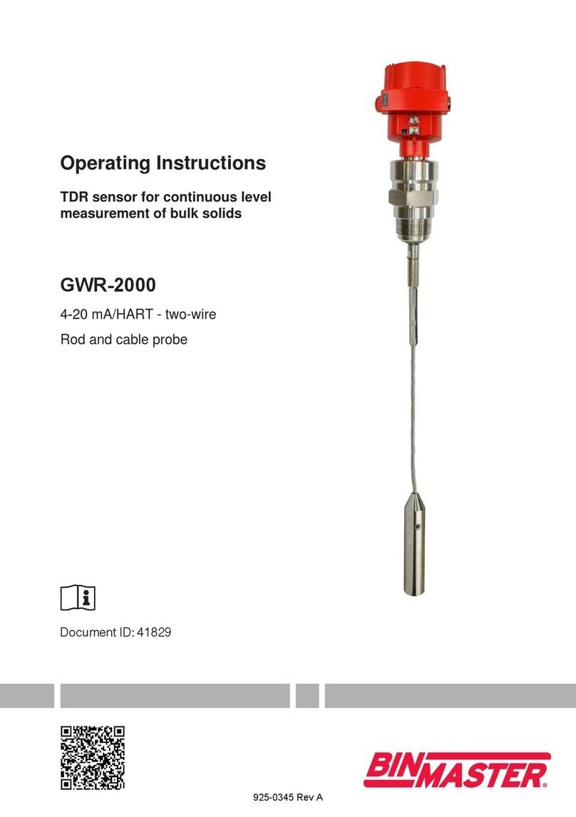
Bin Master GWR-2000 User manual

Bin Master
Bin Master NCR-80 User manual

