Bin Master GWR-2000 User manual
Operating Instructions
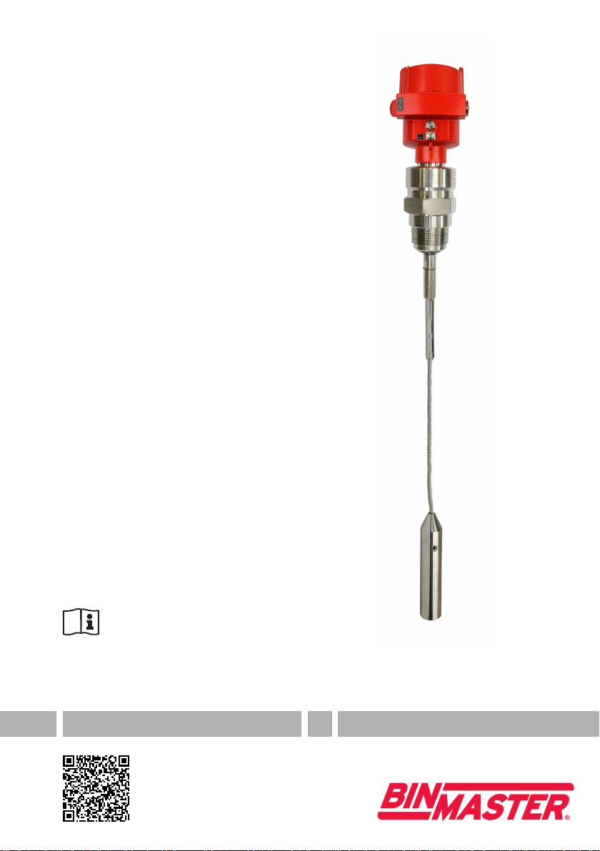
TDR sensor for continuous level
measurement of bulk solids
GWR-2000
4-20 mA/HART - two-wire
Rod and cable probe
Document ID: 41829
925-0345 Rev A

2
Contents
GWR-2000 • 4-20 mA/HART - two-wire
41829-EN-160518
Contents
1 About this document
1.1 Function ........................................................................................................................... 4
1.2 Target group ..................................................................................................................... 4
1.3 Symbols used................................................................................................................... 4
2 For your safety
2.1 Authorised personnel ....................................................................................................... 5
2.2 Appropriate use................................................................................................................ 5
2.3 Warning about incorrect use............................................................................................. 5
2.4 General safety instructions............................................................................................... 5
2.5 CE conformity................................................................................................................... 5
2.6 NAMUR recommendations .............................................................................................. 6
2.7 Environmental instructions ............................................................................................... 6
3 Product description
3.1 Conguration.................................................................................................................... 7
3.2 Principle of operation........................................................................................................ 8
3.3 Packaging, transport and storage..................................................................................... 9
3.4 Accessories and replacement parts ................................................................................. 9
4 Mounting
4.1 General instructions ....................................................................................................... 12
4.2 Mounting instructions ..................................................................................................... 13
5 Connecting to power supply
5.1 Preparing the connection ............................................................................................... 18
5.2 Connecting..................................................................................................................... 19
5.3 Wiring plan, single chamber housing.............................................................................. 21
5.4 Wiring plan, double chamber housing ............................................................................ 21
5.5 Wiring plan, Ex-d-ia double chamber housing................................................................ 23
5.6 Double chamber housing with DISADAPT ..................................................................... 25
5.7 Wiring plan - version IP 66/IP 68, 1 bar........................................................................... 26
5.8 Supplementary electronics............................................................................................. 26
5.9 Switch-on phase............................................................................................................. 27
6 Set up with the display and adjustment module
6.1 Insert display and adjustment module............................................................................ 28
6.2 Adjustment system......................................................................................................... 29
6.3 Parameter adjustment - Quick setup .............................................................................. 31
6.4 Parameter adjustment - Extended adjustment................................................................ 31
6.5 Saving the parameter adjustment data........................................................................... 47
7 Setup with PACTware
7.1 Connect the PC.............................................................................................................. 48
7.2 Parameter adjustment with PACTware............................................................................ 49
7.3 Set up with the quick setup............................................................................................. 50
7.4 Saving the parameter adjustment data........................................................................... 51
8 Set up with other systems
8.1 DD adjustment programs ............................................................................................... 52
8.2 Field Communicator 375, 475 ........................................................................................ 52
9 Diagnostics and servicing
925-0345 Rev A

3
Contents
GWR-2000 • 4-20 mA/HART - two-wire
41829-EN-160518
9.1 Maintenance .................................................................................................................. 53
9.2 Diagnosis memory ......................................................................................................... 53
9.3 Status messages............................................................................................................ 54
9.4 Rectify faults................................................................................................................... 58
9.5 Exchanging the electronics module................................................................................ 60
9.6 Exchange or shorten cable/rod ...................................................................................... 61
9.7 Software update ............................................................................................................. 63
9.8 How to proceed if a repair is necessary.......................................................................... 64
10 Dismount
10.1 Dismounting steps.......................................................................................................... 65
10.2 Disposal ......................................................................................................................... 65
11 Supplement
11.1 Technical data ................................................................................................................ 66
11.2 Dimensions .................................................................................................................... 78
11.3 Industrial property rights................................................................................................. 84
11.4 Trademark ...................................................................................................................... 84
Safety instructions for Ex areas
TakenoteoftheExspecicsafetyinstructionsforExapplications.
These instructions are attached as documents to each instrument
with Ex approval and are part of the operating instructions manual.
Editing status: 2016-04-13
925-0345 Rev A

4
1 About this document
GWR-2000 • 4-20 mA/HART - two-wire
41829-EN-160518
1 About this document
1.1 Function
This operating instructions manual provides all the information you
need for mounting, connection and setup as well as important instruc-
tionsformaintenanceandfaultrectication.Pleasereadthisinforma-
tion before putting the instrument into operation and keep this manual
accessible in the immediate vicinity of the device.
1.2 Target group
This operating instructions manual is directed to trained specialist
personnel.The contents of this manual should be made available to
these personnel and put into practice by them.
1.3 Symbols used
Information, tip, note
This symbol indicates helpful additional information.
Caution: If this warning is ignored, faults or malfunctions can result.
Warning: If this warning is ignored, injury to persons and/or serious
damage to the instrument can result.
Danger: If this warning is ignored, serious injury to persons and/or
destruction of the instrument can result.
Ex applications
This symbol indicates special instructions for Ex applications.
•List
The dot set in front indicates a list with no implied sequence.
→ Action
This arrow indicates a single action.
1 Sequence of actions
Numbers set in front indicate successive steps in a procedure.
Battery disposal
This symbol indicates special information about the disposal of bat-
teries and accumulators.
925-0345 Rev A

5
2 For your safety
GWR-2000 • 4-20 mA/HART - two-wire
41829-EN-160518
2 For your safety
2.1 Authorised personnel
All operations described in this operating instructions manual must
be carried out only by trained specialist personnel authorised by the
plant operator.
During work on and with the device the required personal protective
equipment must always be worn.
2.2 Appropriate use
VEGAFLEX 82 is a sensor for continuous level measurement.
Youcannddetailedinformationabouttheareaofapplicationin
chapter "Product description".
Operational reliability is ensured only if the instrument is properly
usedaccordingtothespecicationsintheoperatinginstructions
manual as well as possible supplementary instructions.
2.3 Warning about incorrect use
Inappropriate or incorrect use of the instrument can give rise to
application-specichazards,e.g.vesseloverllordamagetosystem
components through incorrect mounting or adjustment. Also the pro-
tectivecharacteristicsoftheinstrumentcanbeinuenced.
2.4 General safety instructions
This is a state-of-the-art instrument complying with all prevailing
regulations and guidelines.The instrument must only be operated in a
technicallyawlessandreliablecondition.Theoperatorisresponsible
for the trouble-free operation of the instrument.
During the entire duration of use, the user is obliged to determine the
compliance of the necessary occupational safety measures with the
current valid rules and regulations and also take note of new regula-
tions.
The safety instructions in this operating instructions manual, the na-
tional installation standards as well as the valid safety regulations and
accident prevention rules must be observed by the user.
For safety and warranty reasons, any invasive work on the device
beyond that described in the operating instructions manual may be
carried out only by personnel authorised by the manufacturer. Arbi-
traryconversionsormodicationsareexplicitlyforbidden.
The safety approval markings and safety tips on the device must also
be observed.
2.5 CE conformity
ThedevicefullsthelegalrequirementsoftheapplicableECguide-
lines.ByaxingtheCEmarking,weconrmsuccessfultestingofthe
product.
925-0345 Rev A

6
2 For your safety
GWR-2000 • 4-20 mA/HART - two-wire
41829-EN-160518
YoucanndtheCECerticateofConformityinthedownloadsection
of our homepage.
Electromagnetic compatibility
Instruments in four-wire or Ex-d-ia version are designed for use in an
industrial environment. Nevertheless, electromagnetic interference
from electrical conductors and radiated emissions must be taken into
account, as is usual with class A instruments according to EN 61326-
1.Iftheinstrumentisusedinadierentenvironment,theelectromag-
netic compatibility to other instruments must be ensured by suitable
measures.
2.6 NAMUR recommendations
NAMUR is the automation technology user association in the process
industry in Germany. The published NAMUR recommendations are
acceptedasthestandardineldinstrumentation.
ThedevicefullstherequirementsofthefollowingNAMURrecom-
mendations:
•NE 21 – Electromagnetic compatibility of equipment
•NE 43 – Signal level for malfunction information from measuring
transducers
•NE53–Compatibilityofelddevicesanddisplay/adjustment
components
•NE107–Self-monitoringanddiagnosisofelddevices
For further information see www.namur.de.
2.7 Environmental instructions
Protection of the environment is one of our most important duties.
That is why we have introduced an environment management system
with the goal of continuously improving company environmental pro-
tection.Theenvironmentmanagementsystemiscertiedaccording
to DIN EN ISO 14001.
Pleasehelpusfullthisobligationbyobservingtheenvironmental
instructions in this manual:
•Chapter "Packaging, transport and storage"
•Chapter "Disposal"
925-0345 Rev A
7
3 Product description
GWR-2000 • 4-20 mA/HART - two-wire
41829-EN-160518
3 Product description
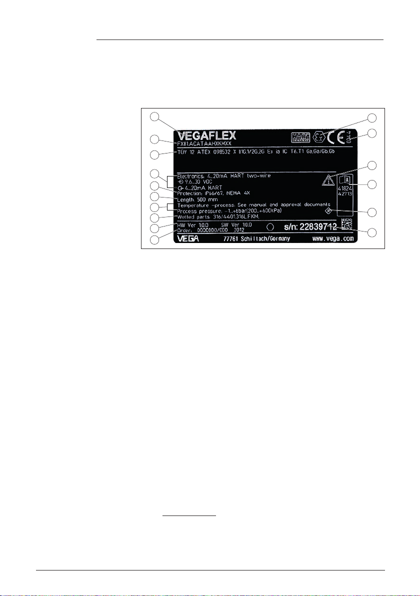
3.1 Conguration
Thetypelabelcontainsthemostimportantdataforidenticationand
use of the instrument:
2
1
13
14
15
16
12
11
5
3
6
4
7
8
9
10
Fig. 1: Layout of the type label (example)
1 Instrument type
2 Product code
3 Approvals
4 Power supply and signal output, electronics
5 Protection rating
6 Probe length
7 Process and ambient temperature, process pressure
8 Material, wetted parts
9 Hardware and software version
10 Order number
11 Serial number of the instrument
12 Symbol of the device protection class
13 ID numbers, instrument documentation
14 Reminder to observe the instrument documentation
15 NotiedauthorityforCEmarking
16 Approval directives
The type label contains the serial number of the instrument. With it
youcanndthefollowinginstrumentdataonourhomepage:
•Product code (HTML)
•Delivery date (HTML)
•Order-specicinstrumentfeatures(HTML)
•Operating instructions and quick setup guide at the time of ship-
ment (PDF)
•Order-specicsensordataforanelectronicsexchange(XML)
•Testcerticate(PDF)-optional
Go to www.vega.com "VEGATools" and "Instrument search". Enter
the serial number.
Alternatively, you can access the data via your smartphone:
•Download the smartphone app "VEGATools" from the "Apple App
Store" or the "GooglePlayStore"
Type label
Serial number - Instru-
ment search
925-0345 Rev A

8
3 Product description
GWR-2000 • 4-20 mA/HART - two-wire
41829-EN-160518
•Scan the Data Matrix code on the type label of the instrument or
•Enter the serial number manually in the app
This operating instructions manual applies to the following instrument
versions:
•Hardware from 1.0.0
•Software from 1.2.0
•OnlyforinstrumentversionswithoutSILqualication
The instrument and the electronics version can be determined via the
product code on the type label as well as on the electronics.
•Standard electronics:Type FX80H.-
The scope of delivery encompasses:
•Sensor
•Documentation
– Quick setup guide
– Testcerticatemeasuringaccuracy(optional)
– Supplementary instructions "GSM/GPRSradiomodule"
(optional)
– Supplementary instructions manual "Heating for display and
adjustment module" (optional)
– Supplementary instructions manual "Plug connector for con-
tinuously measuring sensors" (optional)
– Ex-specic"Safety instructions" (with Ex versions)
– Ifnecessary,furthercerticates
3.2 Principle of operation
The VEGAFLEX 82 is a level sensor with cable or rod probe for con-
tinuous level measurement, suitable for applications in bulk solids.
High frequency microwave pulses are guided along a steel cable or
a rod. Upon reaching the product surface, the microwave pulses are
reected.Therunningtimeisevaluatedbytheinstrumentandoutput-
ted as level.
Probe end tracking
To increase sensitivity, the probe is equipped with probe end tracking.
In bulk solids with a low dielectric constant, this function is very help-
ful.This is the case, for example, in plastic granules, packing chips or
invesselswithuidizedproducts.
Between a dielectric constant of 1.5 and 3, the function switches on, if
required. As soon as the level echo can no longer be detected, probe
end tracking is automatically activated. The measurement is contin-
ued with the last calculated dielectric constant.
The accuracy thus depends on the stability of the dielectric constant.
If you measure a medium with a dielectric constant below 1.5, probe
end tracking is always active. In this case, you have to enter the
Scope of this operating
instructions manual
Versions
Scope of delivery
Application area
Functional principle -
level measurement
925-0345 Rev A

9
3 Product description
GWR-2000 • 4-20 mA/HART - two-wire
41829-EN-160518
dielectric constant of the bulk solid. A stable dielectric constant is very
important here.
3.3 Packaging, transport and storage
Your instrument was protected by packaging during transport. Its
capacity to handle normal loads during transport is assured by a test
based on ISO 4180.
The packaging of standard instruments consists of environment-
friendly, recyclable cardboard. For special versions, PE foam or PE
foil is also used. Dispose of the packaging material via specialised
recycling companies.
Transport must be carried out in due consideration of the notes on the
transport packaging. Nonobservance of these instructions can cause
damage to the device.
The delivery must be checked for completeness and possible transit
damage immediately at receipt. Ascertained transit damage or con-
cealed defects must be appropriately dealt with.
Up to the time of installation, the packages must be left closed and
stored according to the orientation and storage markings on the
outside.
Unless otherwise indicated, the packages must be stored only under
the following conditions:
•Not in the open
•Dry and dust free
•Not exposed to corrosive media
•Protected against solar radiation
•Avoiding mechanical shock and vibration
•Storage and transport temperature see chapter "Supplement -
Technicaldata-Ambientconditions"
•Relative humidity 20 … 85 %
3.4 Accessories and replacement parts
The display and adjustment module PLICSCOM is used for measured
value indication, adjustment and diagnosis. It can be inserted into the
sensor and removed at any time.
Youcanndfurtherinformationintheoperatinginstructions"Display
andadjustmentmodulePLICSCOM" (Document-ID 27835).
The interface adapter VEGACONNECT enables the connection of
communication-capable instruments to the USB interface of a PC. For
parameter adjustment of these instruments, the adjustment software
PACTware with VEGA-DTM is required.
Youcanndfurtherinformationintheoperatinginstructions"Interface
adapterVEGACONNECT" (Document-ID 32628).
Packaging
Transport
Transport inspection
Storage
Storage and transport
temperature
PLICSCOM
VEGACONNECT
925-0345 Rev A

10
3 Product description
GWR-2000 • 4-0 mA/HART - two-wire
41829-EN-160518
The VEGADIS 81 is an external display and adjustment unit for VEGA
plics®sensors.
For sensors with double chamber housing the interface adapter
"DISADAPT" is also required for VEGADIS 81.
Youcanndfurtherinformationintheoperatinginstructions"VE-
GADIS81" (Document-ID 43814).
The adapter "DISADAPT" is an accessory part for sensors with dou-
ble chamber housings. It enables the connection of VEGADIS 81 to
the sensor housing via an M12 x 1 plug.
Youcanndfurtherinformationinthesupplementaryinstructions
"AdapterDISADAPT" (Document-ID 45250).
VEGADIS 82 is suitable for measured value indication and adjustment
of sensors with HART protocol. It is looped into the 4 … 20 mA/HART
signal cable.
Youcanndfurtherinformationintheoperatinginstructions"VE-
GADIS82" (Document-ID 45300).
PLICSMOBILE T61 is an external GSM/GPRS radio unit for transmis-
sion of measured values and for remote parameter adjustment of
plics®sensors. Adjustment is carried out via PACTware/DTM and the
integrated USB connection.
Youcanndfurtherinformationinthesupplementaryinstructions
"PLICSMOBILET61" (Document-ID 37700).
The protective cover protects the sensor housing against soiling and
intense heat from solar radiation.
Youwillndadditionalinformationinthesupplementaryinstructions
manual "Protective cover" (Document-ID 34296).
Screwedangesareavailableindierentversionsaccordingtothe
following standards: DIN 2501, EN 1092-1, BS 10, ASME B 16.5,
JIS B 2210-1984, GOST 12821-80.
Youcanndadditionalinformationinthesupplementaryinstructions
manual "FlangesaccordingtoDIN-EN-ASME-JIS".
The electronics module VEGAFLEX series 80 is a replacement part
forTDRsensorsofVEGAFLEXseries80.Thereisadierentversion
available for each type of signal output.
Youcanndfurtherinformationintheoperatinginstructionsmanual
"ElectronicsmoduleVEGAFLEXseries80".
The display and adjustment module can be optionally replaced by a
display and adjustment module with heating function.
You can use this display and adjustment module in an ambient tem-
perature range of -40 … +70 °C.
Youcanndfurtherinformationintheoperatinginstructions"Display
and adjustment module with heating" (Document-ID 31708).
VEGADIS 81
DISADAPT
VEGADIS 82
PLICSMOBILE T61
Protective cap
Flanges
Electronics module
Display and adjustment
module with heating
925-0345 Rev A

11
3 Product description
GWR-2000 • 4-20 mA/HART - two-wire
41829-EN-160518
If the standard sensor housing is too big or in case of strong vibra-
tions, an external housing can be used.
Then the sensor housing is made of stainless steel. The electronics is
located in the external housing which can be mounted in a distance of
up to 10 m (147 ft) to the sensor by using a connection cable.
Youcanndadditionalinformationintheoperatinginstructions
manual "Externalhousing" (Document-ID 46802).
If you are using an instrument with rod version, you can extend the
rod probe individually with curved segments and rod and cable exten-
sionsofdierentlengths.
All extensions used must not exceed a total length of 6 m (19.7 ft).
The extensions are available in the following lengths:
Rod: ø 16 mm (0.63 in)
•Basic segments: 20 … 5900 mm (0.79 … 232 in)
•Rod/cable segments: 20 … 5900 mm (0.79 … 232 in)
•Curved segments: 100 x 100 mm (3.94 … 3.94 in)
Youcanndfurtherinformationintheoperatinginstructionsmanual
"RodandcablecomponentsVEGAFLEX80series".
If you mount the VEGAFLEX 82 in a bypass tube or standpipe, you
have to avoid contact to the bypass tube by using a spacer at the
probe end.
Youcanndadditionalinformationintheoperatinginstructions
manual "Centering".
External housing
Rod components
Centering
925-0345 Rev A

12
4 Mounting
GWR-2000 • 4-0 mA/HART - two-wire
41829-EN-160518
4 Mounting
4.1 General instructions
Oninstrumentswiththreadedprocesstting,thehexagonmustbe
tightenedwithasuitablewrench.Fortheproperwrenchsizesee
chapter "Dimensions".
Warning:
The housing must not be used to screw the instrument in! Applying
tightening force can damage internal parts of the housing.
Protect your instrument against moisture ingress through the following
measures:
•Use the recommended cable (see chapter "Connectingtopower
supply")
•Tighten the cable gland
•Whenmountinghorizontally,turnthehousingsothatthecable
gland points downward
•Loop the connection cable downward in front of the cable gland
This applies mainly to outdoor installations, in areas where humidity is
expected (e.g. through cleaning processes) and on cooled or heated
vessels.
Metric threads
In the case of instrument housings with metric thread, the cable
glands are screwed in at the factory. They are sealed with plastic
plugs as transport protection.
You have to remove these plugs before electrical connection.
NPT thread
In the case of instrument housings with self-sealing NPT threads, it is
not possible to have the cable entries screwed in at the factory. The
free openings for the cable glands are therefore covered with red dust
protection caps as transport protection.The dust protection caps do
notprovidesucientprotectionagainstmoisture.
Prior to setup you have to replace these protective caps with ap-
proved cable glands or close the openings with suitable blind plugs.
Make sure that all parts of the instrument exposed to the process are
suitable for the existing process conditions.
These are mainly:
•Active measuring component
•Processtting
•Process seal
Process conditions are particularly:
•Process pressure
•Process temperature
•Chemical properties of the medium
•Abrasionandmechanicalinuences
Screwing in
Protection against mois-
ture
Cable glands
Suitability for the process
conditions
925-0345 Rev A
13
4 Mounting
GWR-2000 • 4-20 mA/HART - two-wire
41829-EN-160518
Youcannddetailedinformationontheprocessconditionsinchapter
"Technicaldata" as well as on the type label.
4.2 Mounting instructions
Mount VEGAFLEX 82 in such a way that the distance to vessel instal-
lations or to the vessel wall is at least 300 mm (12 in). In non-metallic
vessels, the distance to the vessel wall should be at least 500 mm
(19.7 in).
During operation, the probe must not touch any installations or the
vessel wall. If necessary, fasten the probe end.
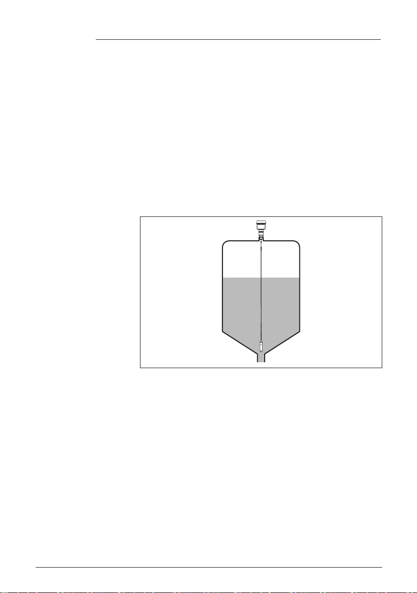
In vessels with conical bottom it can be advantageous to mount the
sensor in the center of the vessel, as measurement is then possible
nearly down to the lowest point of the bottom. Keep in mind that
measurement all the way down to the tip of the probe may not be pos-
sible.The exact value of the min. distance (lower dead band) is stated
in chapter "Technicaldata".
Fig. 2: Vessel with conical bottom
Plastic vessel/Glass vessel
The guided microwave principle requires a metallic surface on the
processtting.Therefore,inplasticvessels,etc.,useaninstru-
mentversionwithange(fromDN50)orplaceametalsheet
(ø>200mm/8in)beneaththeprocessttingwhenscrewingitin.
Makesurethattheplatehasdirectcontactwiththeprocesstting.
When installing the probes without metal vessel wall, e.g. in plastic
vessels,themeasuredvaluecanbeinuencedbystrongelectromag-
neticelds(emittedinterferenceaccordingtoEN61326:classA).
Use a probe in coax version for applications in liquids.
Installation position
Type of vessel
925-0345 Rev A
14
4 Mounting
GWR-2000 • 4-20 mA/HART - two-wire
41829-EN-160518
1 2
Fig. 3: Installation in non-metallic vessel
1 Flange
2 Metal sheet
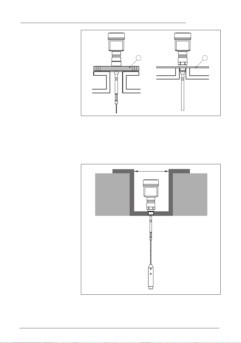
Concrete vessel
When installed in thick concrete ceilings, VEGAFLEX 82 should be
mountedfrontushtotheloweredge.Inconcretesilos,thedistance
to the wall should be at least 500 mm (20 in).
ø >160mm
(ø >6.3")
Fig. 4: Installation in concrete silo
Ifpossible,avoidsockets.Mountthesensorushwiththevesseltop.
If this is not possible, use short sockets with small diameter.
Mounting socket
925-0345 Rev A
15
4 Mounting
GWR-2000 • 4-20 mA/HART - two-wire
41829-EN-160518
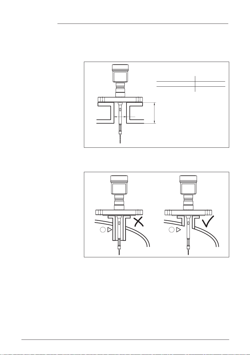
Higher sockets or sockets with a bigger diameter can generally be
used.They can, however, increase the upper blocking distance (dead
band). Check if this is relevant for your measurement.
In such cases, always carry out a false signal suppression after instal-
lation.Youcanndfurtherinformationunder"Setup procedure".
h
d
dh
DN25... DN150
>DN150 ...DN200
≤ 150 mm (5.91")
≤ 100 mm (3.94")
Fig. 5: Mounting socket
Whenweldingthesocket,makesurethatthesocketisushwiththe
vessel top.
1 2
Fig.6:Socketmustbeinstalledush
1 Unfavourable installation
2 Socketush-optimuminstallation
Before beginning the welding work, remove the electronics module
from the sensor. By doing this, you avoid damage to the electronics
through inductive coupling.
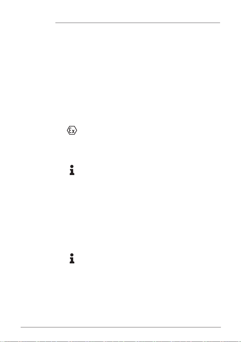
Donotmounttheinstrumentsinorabovethellingstream.Makesure
thatyoudetecttheproductsurface,nottheinowingproduct.
Welding work
Inowingmedium
925-0345 Rev A

16
4 Mounting
GWR-2000 • 4-20 mA/HART - two-wire
41829-EN-160518
Fig.7:Mountingofthesensorwithinowingmedium
The reference plane for the measuring range of the sensors is the
sealingsurfaceofthethreadorange.
Keep in mind that a min. distance must be maintained below the refer-
ence plane and possibly also at the end of the probe - measurement
in these areas is not possible (dead band).The length of the cable
can be used all the way to the end only when measuring conductive
products.Theseblockingdistancesfordierentmediumsarelisted
in chapter "Technicaldata". Keep in mind for the adjustment that the
default setting for the measuring range refers to water.
Theprocessttingmustbesealedifthereisgaugeorlowpressurein
the vessel. Before use, check if the seal material is resistant against
the measured product and the process temperature.
Themax.permissiblepressureisspeciedinchapter"Technical
data" or on the type label of the sensor.
If there is a risk of the cable probe touching the vessel wall during
operation due to product movements or agitators, etc., the measuring
probeshouldbesecurelyxed.
In the gravity weight there is an internal thread (M12), e.g. for an eye-
bolt (optional) - (article no. 2.27423).
Make sure that the probe cable is not completely taut. Avoid tensile
loads on the cable.
Avoidundenedvesselconnections,i.e.theconnectionmustbe
eithergroundedreliablyorisolatedreliably.Anyundenedchangeof
this condition can lead to measurement errors.
If there is a danger of the rod probe touching the vessel wall, then the
probe must be fastened at the bottom end.
Keep in mind that below the fastening, a measurement is not possible.
Measuring range
Pressure
Fasten
925-0345 Rev A

17
4 Mounting
GWR-2000 • 4-20 mA/HART - two-wire
41829-EN-160518
1
2
1
2
Fig. 8: Fasten the probe
1 Measuring probe
2 Retaining sleeve
Incaseofdicultinstallationconditionsinliquidapplications,the
probe can be also mounted laterally. For this purpose, adapt the rod
with rod extensions or bow-shaped segments.
To compensate for the resulting changes in signal runtime, let the
instrument determine the probe length automatically.
The determined probe length can deviate from the actual probe
length when using curved or angled segments.
If internal installations such as struts, ladders, etc. are present on the
vessel wall, the measuring probe should be mounted at least 300 mm
(11.81 in) away from the vessel wall.
Youcanndfurtherinformationinthesupplementaryinstructionsof
the rod extension.
Incaseofdicultinstallationconditions,forexampleinasocket,the
probe can be suitably adapted with a rod extension.
To compensate for the resulting changes in signal runtime, let the
instrument determine the probe length automatically.
Youcanndfurtherinformationinthesupplementaryinstructionsof
the rod and cable components.
Lateral installation
Rod extension
925-0345 Rev A

18
5 Connecting to power supply
GWR-2000 • 4-20 mA/HART - two-wire
41829-EN-160518
5 Connecting to power supply
5.1 Preparing the connection
Always keep in mind the following safety instructions:
Warning:
Connect only in the complete absence of line voltage.
•The electrical connection must only be carried out by trained
personnel authorised by the plant operator.
•If overvoltage surges are expected, overvoltage arresters should
be installed.
Power supply and current signal are carried on the same two-wire
cable.Theoperatingvoltagecandierdependingontheinstrument
version.
Thedataforpowersupplyarespeciedinchapter"Technicaldata".
Provide a reliable separation between the supply circuit and the
mains circuits according to DIN EN 61140 VDE 0140-1.
Keepinmindthefollowingadditionalfactorsthatinuencetheoperat-
ing voltage:
•Lower output voltage of the power supply unit under nominal load
(e.g. with a sensor current of 20.5 mA or 22 mA in case of fault)
•Inuenceofadditionalinstrumentsinthecircuit(seeloadvaluesin
chapter "Technicaldata")
The signal conditioning instruments VEGAMET and VEGASCAN
have digital sensor recognition. When connecting VEGAFLEX 82, an
up-to-date version of the signal conditioning instrument software is
required. For a software update go to "www.vega.com/downloads"
and "Software".
The instrument is connected with standard two-wire cable without
screen. If electromagnetic interference is expected which is above the
test values of EN 61326-1 for industrial areas, screened cable should
be used.
We generally recommend the use of screened cable for HART multi-
drop mode.
Use cable with round cross section for instruments with housing and
cablegland.Toensurethesealeectofthecablegland(IPprotection
rating),ndoutwhichcableouterdiameterthecableglandissuitable
for.
Useacableglandttingthecablediameter.
Metric threads
In the case of instrument housings with metric thread, the cable
glands are screwed in at the factory. They are sealed with plastic
plugs as transport protection.
You have to remove these plugs before electrical connection.
Safety instructions
Voltage supply
Connection to signal con-
ditioning instruments
Connection cable
Cable glands
925-0345 Rev A
19
5 Connecting to power supply
GWR-2000 • 4-20 mA/HART - two-wire
41829-EN-160518
NPT thread
In the case of instrument housings with self-sealing NPT threads, it is
not possible to have the cable entries screwed in at the factory. The
free openings for the cable glands are therefore covered with red dust
protection caps as transport protection.
Prior to setup you have to replace these protective caps with ap-
proved cable glands or close the openings with suitable blind plugs.
With plastic housing, the NPT cable gland or the Conduit steel tube
must be screwed without grease into the threaded insert.
Max. torque for all housings, see chapter "Technicaldata".
If screened cable is required, we recommend connecting the cable
screen on both ends to ground potential. In the sensor, the screen
should be connected directly to the internal ground terminal.The
ground terminal on the outside of the housing must be connected to
the ground potential (with low impedance).
In Ex systems, the grounding is carried out according to the installa-
tion regulations.
In electroplating plants as well as plants for cathodic corrosion protec-
tionitmustbetakenintoaccountthatsignicantpotentialdierences
exist.This can lead to unacceptably high currents in the cable screen
if it is grounded at both ends.
Information:
Themetallicpartsoftheinstrument(processtting,sensor,concen-
tric tube, etc.) are connected with the internal and external ground
terminal on the housing.This connection exists either directly via
the conductive metallic parts or, in case of instruments with external
electronics, via the screen of the special connection cable.
Youcanndspecicationsonthepotentialconnectionsinsidethe
instrument in chapter "Technicaldata".
5.2 Connecting
The voltage supply and signal output are connected via the spring-
loaded terminals in the housing.
Connection to the display and adjustment module or to the interface
adapter is carried out via contact pins in the housing.
Information:
The terminal block is pluggable and can be removed from the
electronics.To do this, lift the terminal block with a small screwdriver
and pull it out. When reinserting the terminal block, you should hear it
snap in.
Proceed as follows:
1. Unscrew the housing lid
2. If a display and adjustment module is installed, remove it by turn-
ing it slightly to the left.
Cable screening and
grounding
Connection technology
Connection procedure
925-0345 Rev A

20
5 Connecting to power supply
GWR-2000 • 4-20 mA/HART - two-wire
41829-EN-160518
3. Loosen compression nut of the cable gland and remove blind
plug
4. Remove approx. 10 cm (4 in) of the cable mantle, strip approx.
1 cm (0.4 in) of insulation from the ends of the individual wires
5. Insert the cable into the sensor through the cable entry
Fig.9:Connectionsteps5and6-Singlechamberhousing
Fig.10:Connectionsteps5and6-Doublechamberhousing
6. Insert the wire ends into the terminals according to the wiring plan
Information:
Solidcoresaswellasexiblecoreswithwireendsleevesareinsert-
eddirectlyintotheterminalopenings.Incaseofexiblecoreswithout
end sleeves, press the terminal from above with a small screwdriver,
the terminal opening is then free.When the screwdriver is released,
the terminal closes again.
925-0345 Rev A
Other manuals for GWR-2000
2
Table of contents
Other Bin Master Accessories manuals

Bin Master
Bin Master CNCR-220 User manual

Bin Master
Bin Master CNCR-230 User manual

Bin Master
Bin Master CNCR-120 User manual

Bin Master
Bin Master SmartBob AO User manual

Bin Master
Bin Master NCR-21 User manual

Bin Master
Bin Master NCR-84 User manual

Bin Master
Bin Master NCR-25 User manual

Bin Master
Bin Master CNCR-190 User manual

Bin Master
Bin Master NCR-80 User manual

Bin Master
Bin Master NCR-80 User manual


