Bin Master FD-2000 User manual

По вопросам продаж и поддержки обращайтесь:
Архангельск (8182)63‐90‐72
Астана (7172)727‐132
Белгород (4722)40‐23‐64
Брянск (4832)59‐03‐52
Владивосток (423)249‐28‐31
Волгоград (844)278‐03‐48
Вологда (8172)26‐41‐59
Воронеж (473)204‐51‐73
Екатеринбург (343)384‐55‐89
Иваново (4932)77‐34‐06
Ижевск (3412)26‐03‐58
Казань (843)206‐01‐48
Калининград (4012)72‐03‐81
Калуга (4842)92‐23‐67
Кемерово (3842)65‐04‐62
Киров (8332)68‐02‐04
Краснодар (861)203‐40‐90
Красноярск (391)204‐63‐61
Курск (4712)77‐13‐04
Липецк (4742)52‐20‐81
Магнитогорск (3519)55‐03‐13
Москва (495)268‐04‐70
Мурманск (8152)59‐64‐93
Набережные Челны (8552)20‐53‐41
Нижний Новгород (831)429‐08‐12
Новокузнецк (3843)20‐46‐81
Новосибирск (383)227‐86‐73
Орел (4862)44‐53‐42
Оренбург (3532)37‐68‐04
Пенза (8412)22‐31‐16
Пермь (342)205‐81‐47
Ростов‐на‐Дону (863)308‐18‐15
Рязань (4912)46‐61‐64
Самара (846)206‐03‐16
Санкт‐Петербург (812)309‐46‐40
Саратов (845)249‐38‐78
Смоленск (4812)29‐41‐54
Сочи (862)225‐72‐31
Ставрополь (8652)20‐65‐13
Тверь (4822)63‐31‐35
Томск (3822)98‐41‐53
Тула (4872)74‐02‐29
Тюмень (3452)66‐21‐18
Ульяновск (8422)24‐23‐59
Уфа (347)229‐48‐12
Челябинск (351)202‐03‐61
Череповец (8202)49‐02‐64
Ярославль (4852)69‐52‐93
Единый адрес: [email protected] Веб‐сайт: www.binmaster.nt-rt.ru
FD-2000 BinMaster
Solids Flow Detect
Model FD-2000
925-0322 Rev C 0415

925-0322 Rev C 0415
Solids Flow Detect Model FD-2000
TABLE OF CONTENTS
SAFETY SUMMARY .......................................................................................................... 3
SPECIFICATIONS ............................................................................................................. 4
1.0 INTRODUCTION/DESCRIPTION............................................................................... 5
2.0 LOCATION AND MOUNTING .................................................................................... 5
3.0 CONNECTIONS AND WIRING................................................................................... 8
5.0 CONTROLS AND INDICATORS............................................................................... 10
6.0 CALIBRATION PROCEDURE................................................................................... 12

0415925-0322 Rev C
Solids Flow Detect Model FD-2000
Solids Flow Detect Model FD-2000
SAFETY SUMMARY
Review the following safety precautions to avoid injury and prevent damage to the equipment.
The product should be installed, commissioned, and maintained by qualied and authorized
personnel only.
Install according to installation instructions and comply with all National and Local codes.
Use electrical wire that is sized and rated for the maximum voltage and current of the application.
Properly ground the enclosure to an adequate earth ground.
Observe all terminal and relay contact ratings as called out on the nameplate and in the
installation manual.
Insure that the enclosure cover is in place and secured tightly during normal operation.
If this product is used in a manner not specied by the manufacturer the safety protection
could be compromised.
Safety Terms and Symbols
WARNING: Warning statements identify conditions or practices that could result in
injury or loss of life. Risk of electrical shock.
CAUTION: Caution statements identify conditions or practices that could result in
damage to this product or other property.

925-0322 Rev C 0415
Solids Flow Detect Model FD-2000
SPECIFICATIONS
Power Requirements: 2.0 Watts at 24 VDC +/-10%
Operating Temperature: -22°F to +140°F (-30°C to +60°C)
Storage Temperature: -40°F to +176°F (-40°C to +80°C)
Detection Range: 1.5 m (4.9 ft)
Output Delay Range: Switchable: 0.1 to 3.1 sec / 2.3 to 15.1 sec
Relay Outputs: 250 VAC / 220 VDC / 2A
4-20mA Output: No Flow: 4 mA +/-4%
Flow: 20 mA +/-4%
Fault: 22 mA +/-4%
4-20mA Load: 650 Ohms Maximum
Emissions: 24.11 GHz, 6.6 mW typical/9.9 mW maximum
Enclosure: White Powder Coated Aluminum, NEMA 4X
Mounting: 1-1/4 inch NPS
Conduit Entry: 3/4 inch NPT
Process Pressure: 80 psi

0415925-0322 Rev C
Solids Flow Detect Model FD-2000
Solids Flow Detect Model FD-2000
The model FD-2000 solids ow detector is an industrial instrument that senses ow or no-ow condi-
tions of solids and powders in pneumatic pipelines, gravity chutes and feeders. It uses microwave
Doppler technology to provide highly sensitive motion detection. The sensor is completely non-intru-
sive, avoiding contact with the ow stream and associated wear problems.
The FD-2000 is a single piece system that contains the sensing element, the power and output con-
nections and user adjustment controls. It provides both a relay output and current output for indica-
tion of ow or no-ow. Both normally closed and normally open contacts are available at the relay
output.
The FD-2000 sensor unit emits a low power microwave signal toward the material being monitored.
Part of this signal is reected off the material back to the transducer of the FD-2000. This reected
signal combines with the emitted signal to produce a beat frequency, which is the difference in fre-
quency between the two signals. If the material being monitored is not moving, the reected signal
will be the same frequency as the emitted signal and there will be no beat frequency produced.
However, if the material is moving, the reected signal will be shifted in frequency and a difference
or beat frequency will be produced. This shift in frequency is called the Doppler Effect. The presence
or absence of this beat frequency is sensed by the FD-2000 to detect a ow or no ow condition.
Microwaves are extremely high frequency radio waves and as such pass through non-metallic mate-
rials with negligible attenuation. This means that the FD-2000 can see through a plastic pipe, a glass
process seal or the wall of a wooden chute to detect the motion of material inside. This also means
that the FD-2000 can look all the way through a plastic pipe or wooden chute and see a person
walking on the opposite side. Therefore, in some installations where this situation may occur, a me-
tallic material will need to be placed on the opposite side of the pipe or chute to prevent the FD-2000
from seeing objects on the other side. Adjusting the sensitivity of the FD-2000 to a lower setting may
eliminate the sensing of moving objects on the other side of a nonmetallic pipe or chute.
Location and Mounting
The FD-2000 is mounted at the process site where the movement of material is to be monitored.
Often this will be on the side of a chute or ow pipe where access by personnel is difcult or limited.
When selecting a location, attention should be given to the temperature limits of the sensor to make
sure they are not exceeded. And, although the unit is equipped with a lter to reduce the effects of
mounting vibrations, it should be mounted where it will not experience excessive vibration as this
can be detected as motion and give a false indication of ow.
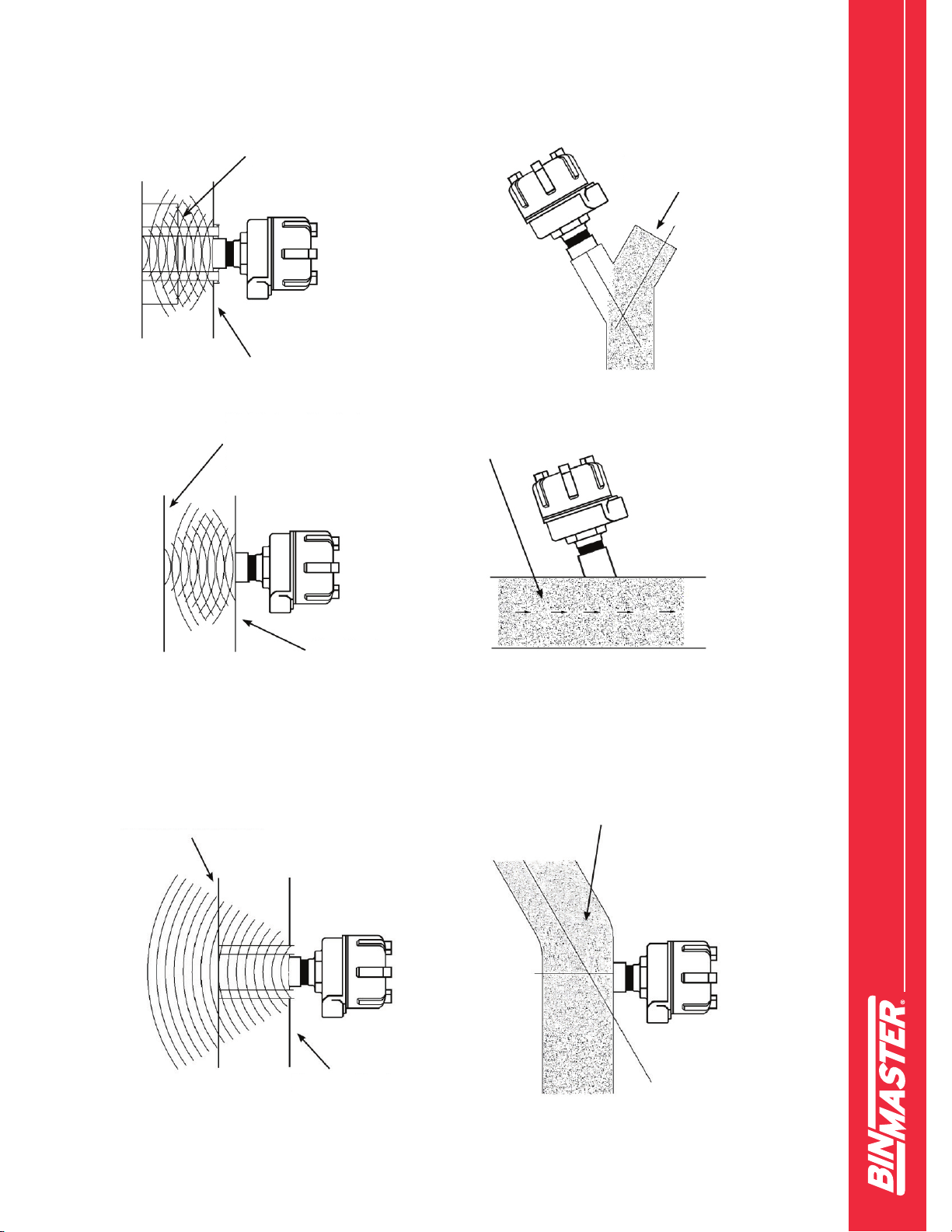
The sensor best detects movement of material moving directly toward or away from the unit. How-
ever, mounting the unit perpendicular to ow usually works because there is adequate uctuation
of material as it ows past to allow detection. In some cases where the material is very light and dif-
cult to detect, it may be necessary to mount the unit at some angle off perpendicular to the ow. An
angle of 20 to 30 degrees from perpendicular is usually sufcient. Refer to Figure 1 for examples.
INTRODUCTION/DESCRIPTION
925-0322 Rev C 0415
Solids Flow Detect Model FD-2000
Poor Mounting Practice
Good Mounting Practice
Figure 1
Metal shield will
inhibit detection of
external movement.
Material ows away
from sensor. Non-
contact with sensor.
Material ows away
from sensor.
Metal pipe will reect
signal which eliminates
detection of external
movement.
Non-mettallic pipe without a
metal shield permits detection
of external movement.
Avoid ow towards
the sensor mount.
Non-metallic pipe
Metallic pipe
Non-metallic pipe

0415925-0322 Rev C
Solids Flow Detect Model FD-2000
Solids Flow Detect Model FD-2000
For installations where the sensor needs to monitor ow through a metal pipe or chute, an
opening will have to be made in the metal wall. If necessary, a suitable seal made of nonmetal-
lic material should be provided for this opening. For some installations, the seal provided on
the FD-2000 sensor would be adequate. Care must be taken so as not to exceed the pressure
or temperature rating of the FD-2000.
The unit should be mounted so that the conduit openings are down, as shown in Figure 2.
If being used in an environment with high levels of moisture or moist air, then the conduit
openings should be sealed with a duct seal compound or appropriate putty.
To summarize, the FD-2000 sensor should be installed such that:
• Its temperature rating is not exceeded
• Its pressure rating is not exceeded
• It does not experience excessive vibration
• An opening is provided in metallic shoots or pipes
• If necessary, mounted off perpendicular to material ow
• Always mount conduit openings down and, if necessary, use duct seal
Figure 2

925-0322 Rev C 0415
Solids Flow Detect Model FD-2000
Connections and Wiring
Terminals are available for the following connections:
• 24 VDC
• 4-20 mA
• OUT
• FAULT
These terminals are accessible by unscrewing the enclosure cover. All wiring should be fed
from the outside, through the conduit openings. Terminal labels are printed directly above the
terminals on the control plate as seen in Figure 3.
24 VDC
The FD-2000 requires about 2.0 watts of power from a 24 VDC +/-10% source. Refer to Figure
3 for location of these two terminals. Connect the negative of the 24 VDC power source to the
far left terminal labeled with the minus sign. Connect the positive to the terminal labeled with
the plus sign. A good earth should also be connected at the screw terminal on the inside of the
enclosure.
4-20 mA
This is a powered or active current output and can drive up to 650 ohms. Refer to Figure 3 for
location of these two terminals. Connect the negative wire coming from the current receiver
to the terminal labeled with the minus sign. Connect the positive wire coming from the current
receiver to the terminal labeled with the plus sign.
Figure 3
0415925-0322 Rev C
Solids Flow Detect Model FD-2000
Solids Flow Detect Model FD-2000
OUT and FAULT
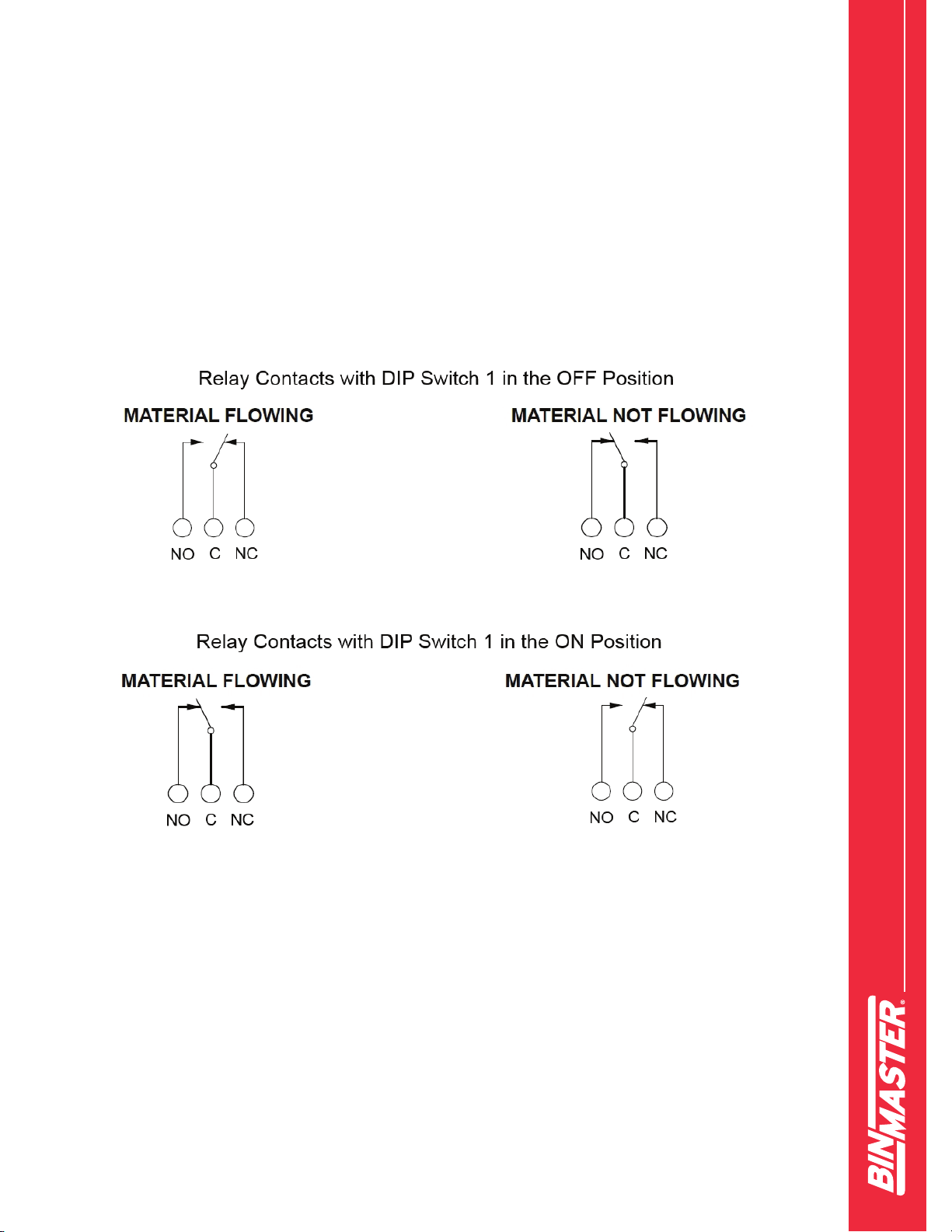
Each of the OUT and FAULT terminals offer an SPDT relay which provides dry contacts
for operation of external controls or equipment. Terminal connections are available for the
common (C), the normally open (NO) and the normally closed contacts (NC). Refer to Fig-
ure 3 for location of these terminals. The relay contacts are rated for 2A at up to 250 VAC
or 220 VDC.
Figure 4

925-0322 Rev C 0415
Solids Flow Detect Model FD-2000
Controls and Indicators
All user controls and indicators are visible by removing the enclosure cover. Refer to Figure 5 for
location of the controls and indicators.
Following is a list of controls and indicators available:
FLOW Indicator – This is to assist in adjusting the sensitivity by indicating the margin between
the no-ow and ow conditions. It consists of ve multi-colored LEDs, with a red one in the
center representing the trip point between ow and no-ow. Indication to the left is no-ow
and to the right is ow.
OUT Indicator – This is a yellow LED and will indicate the Flow or No Flow output condition,
which corresponds directly with the OUT relay and 4-20mA output current. When the OUT
indicator is off, the OUT relay is de-energized and the current output is at 4mA. When the
OUT indicator is on, the OUT relay is energized and the current output is at 20mA.
FAULT Indicator – This is a red LED and will indicate if the OUT condition is not guaranteed
to be valid; such as when the unit is operating near or outside its rated temperature range or
when the internal Doppler sensing element is faulty. This indicator corresponds directly with
Figure 5

0415925-0322 Rev C
Solids Flow Detect Model FD-2000
Solids Flow Detect Model FD-2000
the FAULT relay. When the FAULT indicator is off, the FAULT relay is de-energized. When the
FAULT indicator is on, the FAULT relay is energized. Also, the 4-20mA current output will be
at 22mA when in the FAULT condition.
POWER Indicator – This is a green LED and simply indicates when power is applied to the unit.
SENSITIVITY Control – This is used to adjust the sensitivity or detection range of the unit.
FLOW DELAY Control – This is used to adjust the delay from when material has started to
ow to when the OUT relay and indicator are switched.
NO FLOW DELAY Control – This is used to adjust the delay from when material has stopped
owing to when the OUT relay and indictor are switched.
DIP Switches
Switch 1 (NO FLOW OUTPUT / FLOW OUTPUT) – For selecting between a no-ow or
ow output condition. The OUT relay will be energized and the OUT indicator will be on
based on this selection. Slide the switch to the off position for a no ow output. Slide the
switch to the on position for a ow output.
Switch 2 (FLOW DELAY 3 SEC / FLOW DELAY 15 SEC) – For selecting the desired
ow delay range. Slide the switch to the off position for an on delay range of 0.1 to 3.1
seconds. Slide the switch to the on position for a range of 2.3 to 15.1 seconds.
Switch 3 (NO FLOW DELAY 3 SEC / NO FLOW DELAY 15 SEC) – For selecting the
desired no ow delay range. Slide the switch to the off position for an off delay range of
0.1 to 3.1 seconds. Slide the switch to the on position for a range of 2.3 to 15.1 seconds.
Switch 4 (SENSITIVITY LOW / SENSITIVITY HIGH) – For selecting the sensitivity or
detection range of the unit. Slide this switch to the off position for low sensitivity or when
the moving target will be near the unit. Slide this switch to the on position for high
sensitivity or when the target will be far from the unit.
Switch 5 (VIBRATION FILTER OFF / VIBRATION FILTER ON) – For enabling or
disabling the vibration lter, which will eliminate undesirable signals from vibrating
equipment. Slide this switch to the off position to turn the lter off. Slide this switch to
the on position to turn the lter on.

925-0322 Rev C 0415
Solids Flow Detect Model FD-2000
Calibration Procedure
With the sensor mounted in position and wired, unscrew the enclosure cover to expose
the control plate. Then follow these steps:
1. Start with the DIP switches set as follows:
a. Switch 1 on for a FLOW OUTPUT.
b. Switch 2 off for FLOW DELAY 3 SEC.
c. Switch 3 off for NO FLOW DELAY 3 SEC.
d. Switch 4 off for SENSITIVITY LOW.
e. Switch 5 off for VIBRATION FILTER OFF.
2. Turn the SENSITIVITY, FLOW DELAY and NO FLOW DELAY controls fully counter
clock-wise for their minimum setting.
3. With no material owing (the OUT indicator should be off), slowly turn the SENSITIVITY
control clock-wise until the OUT indicator turns on or until the control is at maximum.
Note the actuating point for the no-ow condition.
4. Start material owing and slowly turn the SENSITIVITY control counter clock-wise until
the OUT indicator just turns off. Note the actuating point for the ow condition.
5. Turn the SENSITIVITY control midway between the no-ow and ow actuating points.
If vibration is causing unwanted detection or increases the receiving level of the no-ow
condition, then set DIP switch 5 to VIBRATION FILTER ON and repeat steps 2 to 5. If the
owing material is not detectable or there is very little margin between the no-ow and
ow actuating points, then set DIP switch 4 to SENSITIVITY HIGH and repeat steps
2 to 5.
6. In order to detect irregular ow, set DIP switch 2 and adjust the FLOW DELAY control
as needed.
7. In order to not detect irregular ow, set DIP switch 3 and adjust the NO FLOW DELAY
control as needed.
8. If the desired output is for indication of no ow, then you can set DIP switch 1 for
NO FLOW OUTPUT.

925-0322 Rev C 0415
Solids Flow Detect Model FD-2000
Solids Flow Detect Model FD-2000
LIMITED WARRANTY
Garner Industries warrants this product against defects in material and workman-
ship for two (2) years according to the following terms;
1.) This warranty extends to the original purchaser only and commences on the
date of original purchase.
2.) Garner Industries sole obligation under said warranty is to repair, or at its option
replace the defective parts. The buyer shall have no other remedy. All special,
incidental and consequential damages are excluded. The buyer must deliver
the product under warranty prepaid to the factory. Garner Industries obligation
is limited to the cost of material and labor to repair or replace, and does not
include transportation expenses.
3.) This warranty shall be voided, in our sole judgment, by alterations of equipment
except by Garner Industries, or tampering with, improper installation or mainte-
nance, accident or misuse, or act of God. This warranty expressly excludes all
damage to the product resulting from careless or neglectful packaging or trans-
portation. The warranty does not extend to repairs made necessary by normal
wear.
4.) This warranty is in lieu of all other warranties, expressed or implied including
any implied warranties or merchantability or tness for particular purpose. No
employee, agent, franchise dealer or other person is authorized to give any
warranties of any nature on behalf of Garner Industries.
5) Garner Industries shall in no event be responsible for any warranty work done
without first obtaining Garner Industries written consent.
6) Except as provided herein, Garner Industries shall have no liability, loss or
damage caused or alleged to be caused directly or indirectly by this equipment.
7) This warranty gives the buyer specific legal rights, and you may also have other
rights which vary from state to state.
8)

925-0322 Rev C 0415
Solids Flow Detect Model FD-2000
Declaration of Conformity
BinMaster declares that all models of the FD-2000 flow sensor devices as listed below
comply with the following directives and harmonized standards. This product if installed,
operated and maintained as described in this manual will provide a safe and reliable
bulk solids flow / no flow sensor for a variety of materials.
Product: Solids ow sensor
Models: FD-2000
All test reports and documentation are held and can be obtained from
BinMaster.

По вопросам продаж и поддержки обращайтесь:
Архангельск (8182)63‐90‐72
Астана (7172)727‐132
Белгород (4722)40‐23‐64
Брянск (4832)59‐03‐52
Владивосток (423)249‐28‐31
Волгоград (844)278‐03‐48
Вологда (8172)26‐41‐59
Воронеж (473)204‐51‐73
Екатеринбург (343)384‐55‐89
Иваново (4932)77‐34‐06
Ижевск (3412)26‐03‐58
Казань (843)206‐01‐48
Калининград (4012)72‐03‐81
Калуга (4842)92‐23‐67
Кемерово (3842)65‐04‐62
Киров (8332)68‐02‐04
Краснодар (861)203‐40‐90
Красноярск (391)204‐63‐61
Курск (4712)77‐13‐04
Липецк (4742)52‐20‐81
Магнитогорск (3519)55‐03‐13
Москва (495)268‐04‐70
Мурманск (8152)59‐64‐93
Набережные Челны (8552)20‐53‐41
Нижний Новгород (831)429‐08‐12
Новокузнецк (3843)20‐46‐81
Новосибирск (383)227‐86‐73
Орел (4862)44‐53‐42
Оренбург (3532)37‐68‐04
Пенза (8412)22‐31‐16
Пермь (342)205‐81‐47
Ростов‐на‐Дону (863)308‐18‐15
Рязань (4912)46‐61‐64
Самара (846)206‐03‐16
Санкт‐Петербург (812)309‐46‐40
Саратов (845)249‐38‐78
Смоленск (4812)29‐41‐54
Сочи (862)225‐72‐31
Ставрополь (8652)20‐65‐13
Тверь (4822)63‐31‐35
Томск (3822)98‐41‐53
Тула (4872)74‐02‐29
Тюмень (3452)66‐21‐18
Ульяновск (8422)24‐23‐59
Уфа (347)229‐48‐12
Челябинск (351)202‐03‐61
Череповец (8202)49‐02‐64
Ярославль (4852)69‐52‐93
Единый адрес: [email protected] Веб‐сайт: www.binmaster.nt-rt.ru
Table of contents
Other Bin Master Accessories manuals

Bin Master
Bin Master NCR-80 User manual

Bin Master
Bin Master NCR-25 User manual

Bin Master
Bin Master SmartBob AO User manual

Bin Master
Bin Master CNCR-190 User manual

Bin Master
Bin Master NCR-80 User manual

Bin Master
Bin Master NCR-80 User manual

Bin Master
Bin Master CNCR-120 User manual

Bin Master
Bin Master NCR-21 User manual

Bin Master
Bin Master NCR-84 User manual

Bin Master
Bin Master CNCR-230 User manual


