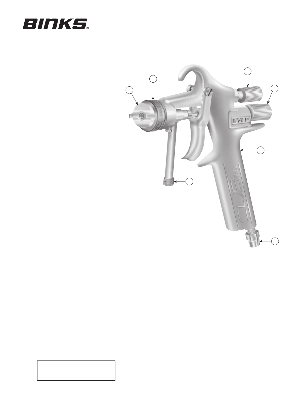
Your new Binks Mach 1 Cub SL HVLP
gun is exceptionally rugged in con-
struction and is built to stand up under
hard, continuous use. However, like any
other precision instrument. its most
efficient operation depends on a knowl-
edge of its construction, operation and
maintenance. Properly handled and
cared for, it will produce beautiful,
uniform finishes long after other spray
guns are worn out.
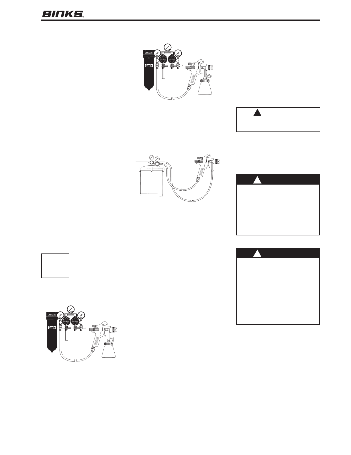
The Mach 1 Cub SL gun can be used in
three modes: siphon feed, pressure
assist, or pressure feed tank hook-ups.
In siphon mode, lowered air pressure in
the gun draws fluid from the cup into
the gun. The pressure assist function
works when air flows through the cup’s
check valve assembly, pressurizing the
liquid in the cup and and forcing it up
into the gun. Pressure feed modes for
tanks rely on systems that separately
regulate fluid and air flow. Instructions
for assembling the gun with either the
siphon cup or pressure assist cup are
included here and also with the cup
assemblies. Below are brief descrip-
tions and illustrations of the siphon
feed, the pressure assist, and the
pressure feed tank hook-ups.
SIPHON FEED CUP HOOK-UP
Air pressure for atomization is regulat-
ed at extractor. The amount of fluid is
adjusted by fluid control knob on gun,
viscosity of paint, and air pressure.
PRESSURE ASSIST CUP HOOK-UP
Air pressure for atomization is regulated
at the extractor. The fluid pressure is
from the front of the gun, through check
valve to cup.
PRESSURE FEED TANK
HOOK-UPS
For portable painting operations, use
a double regulator pressure feed tank
hook-up. Air pressure for atomization
and for fluid supply is regulated by two
separate air regulators on tank. The Mach
1 Cub SL comes standard with a 40T
fluid nozzle to be used in siphon feed
operations, see note on page 7 regarding
nozzle options and materials use.
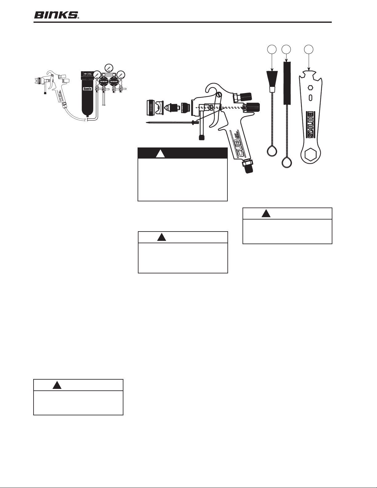
HOW TO SET UP YOUR GUN
FOR SIPHON APPLICATIONS
(See Cup Part Sheet for Parts
Identification)
1. Attach one end of vent tube to
connector on cup lid.
2. Push the other end of vent tube down
through loop on side of cup lip.
3. Insert the threaded fluid inlet into
the swivel nut, taking care to
position the vent tube away from
the gun trigger.
4. Rotate the swivel nut until tight to
attach the cup to the fluid inlet.
HOW TO SET UP YOUR GUN
FOR PRESSURE ASSIST
OPERATIONS
1. Screw the swivel nut onto the
threaded end of the fluid inlet.
2. Remove the 1/4" plug and gasket
from the gun.
3. Replace the plug and gasket with
the connector supplied with the cup
assembly.
4. Slip the longer end of the check
valve assembly over the gun connec-
tor and attach the shorter end to the
connector on the cup lid.
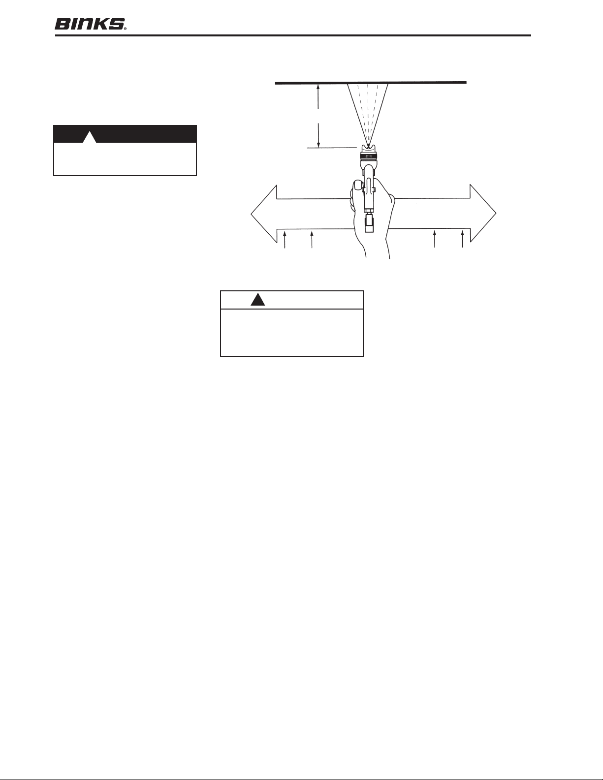
CONNECTING TO AIR HOSE
CONTROLLING FLUID FLOW
Air pressure for atomization is regulat-
ed at the extractor (see illustration pg.
4). The flow of fluid is adjusted by the
fluid control knob on the gun, and by
paint viscosity, air pressure, and nozzle
size. Nozzles with larger apertures give
higher flow rates. You can adjust fluid
flow by turning the fluid control knob.
Turn clockwise to restrict the needle
opening, counterclockwise to enlarge it.
3
HOW TO SET UP and OPERATE YOUR Binks Cub SL HVLP SPRAY GUN
CAUTION
Over-tightening connector will dam-
age its delicate threading.
!
WARNING
REGARDING AIR PRESSURE SAFETY
Shut off air pressure before connect-
ing or disconnecting air hose or
removing any components from the
gun. Air should be supplied by a suit-
able length of 1/4" diameter air hose
fitted with a 1/4" NPS(f) connector at
the gun end. For hose lengths over
25', use 5/16" diameter hose.
!
WARNING
REGARDING PAINTS, SOLVENTS AND
OTHER COATINGS SAFETY
Do not use open containers for stor-
age or disposal of paint, other coat-
ings, cloth, or paper used in
preparation and application. Many
paints and coatings contain volatile
chemicals that are a cause of pollu-
tion and are a health and fire hazard.
Always wear appropriate clothing,
including gloves, and eye protection,
and a respirator when using the gun.
!
CA PROP
65
PROP 65 WARNING
WARNING: This product
contains chemicals known
to the State of California to
cause cancer and birth
defects or other
reproductive harm.