Binks TROPHY 2466 SERIES User manual

EN
77-3027-R1.0 1 / 16
BINKS “TROPHY” SERIES
GRAVITY FEED
HVLP, LVMP & CONVENTIONAL
MANUAL SPRAY GUNS
(2466-XXXX-XXXX)
Binks Trophy Series Gravity Spray Gun
is the premier spray gun for use in
gravity feed spray applications and sets a
new standard in durability, ergonomics,
and atomization. The lightweight
ergonomic design offers unsurpassed
comfort and control. The latest advanced
atomization technology has been
incorporated for achieving consistent,
fine finishes when spraying a wide range
of industrial coating applications.
Binks Trophy Series Gravity Spray Guns
are offered in three different atomization
technologies: HVLP, LVMP and
Conventional.
SPECIFICATIONS
Maximum Air Pressure 140 psi / 9.6 bar (P-1)
Gun Body Anodized Aluminum
Fluid Path Stainless Steel
Fluid Inlet Size 3/8" – 19 NPS / BSP(f)
Air Inlet Size 1/4" NPS / BSP(m)
Gun Weight 13.8 oz. / 394 grams (less cup)
Wetted Parts Stainless Steel & PTFE
READ ALL INSTRUCTIONS BEFORE OPERATING THIS BINKS PRODUCT.
IMPORTANT! DO NOT DESTROY
It is the customer's responsibility to have all operators and service personnel read and understand this manual.
Contact your local Binks representative for additional copies of this manual.
The Trophy HVLP Series of Spray
Guns can be used to operate
at high transfer efficiencies in
compliance with “California South
Coast Air Quality Management
District” regulations as a High
Volume, Low Pressure spray gun.
II 2 G X
SERVICE MANUAL

EN
77-3027-R1.02 / 16
Binks reserves the right to modify equipment specification without prior notice.
EC Declaration of Conformity
Manuf. By: Finishing Brands
195 Internationale Blvd.
Glendale Heights, IL 60139
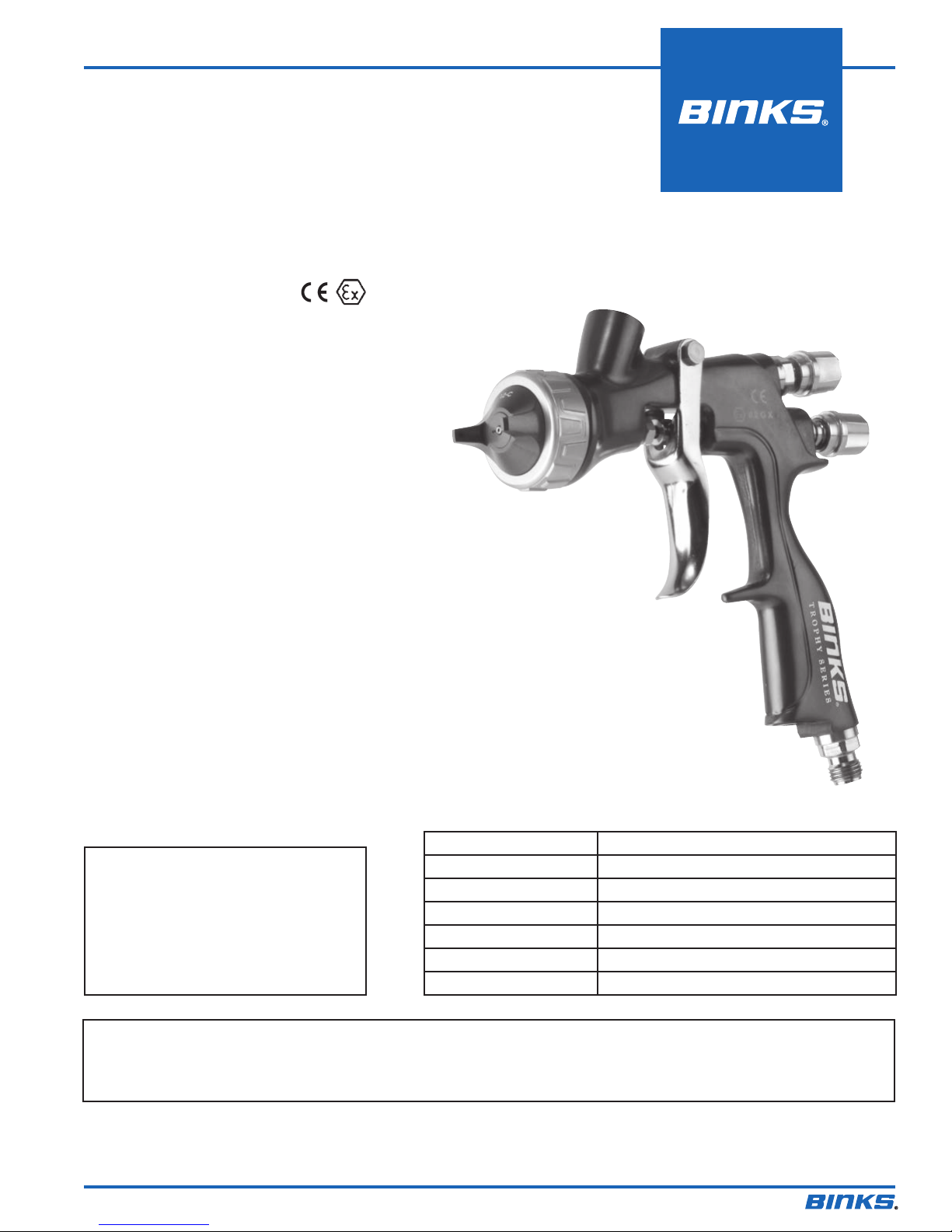
Type/Series: Handheld Spray Guns
Model: Binks “Trophy” Series
The equipment to which this document relates is in conformance with the following standards or other normative references:
BS EN IS0 12100:2010 and BS EN 1953:1998 + A1:2009 and thereby conform to the protection requirements of Council
Directive 2006/42/EC relating to Machinery Safety Directive, and;
BS EN 13463-1:2009, Council Directive 94/9/EC relating to Equipment and Protective Systems for use in Potentially Explosive
Atmospheres, protection level II 2 G X.
Approved By: _____________________________ Date: ______________
Binks
Marvin Burns August 1, 2013
WARNING
!
In this part sheet, the words WARNING, CAUTION and NOTE are used to emphasize important safety information as follows:
!
CAUTION
Hazards or unsafe practices which could
result in minor personal injury, product
or property damage.
!
WARNING
Hazards or unsafe practices which could
result in severe personal injury, death or
substantial property damage.
NOTE
Important installation, operation or
maintenance information.
Read the following warnings before using this equipment.
FOR FURTHER SAFETY INFORMATION REGARDING BINKS AND DEVILBISS EQUIPMENT,
SEE THE GENERAL EQUIPMENT SAFETY BOOKLET (77-5300).
IT IS THE RESPONSIBILITY OF THE EMPLOYER TO PROVIDE THIS INFORMATION TO THE OPERATOR OF THE EQUIPMENT.
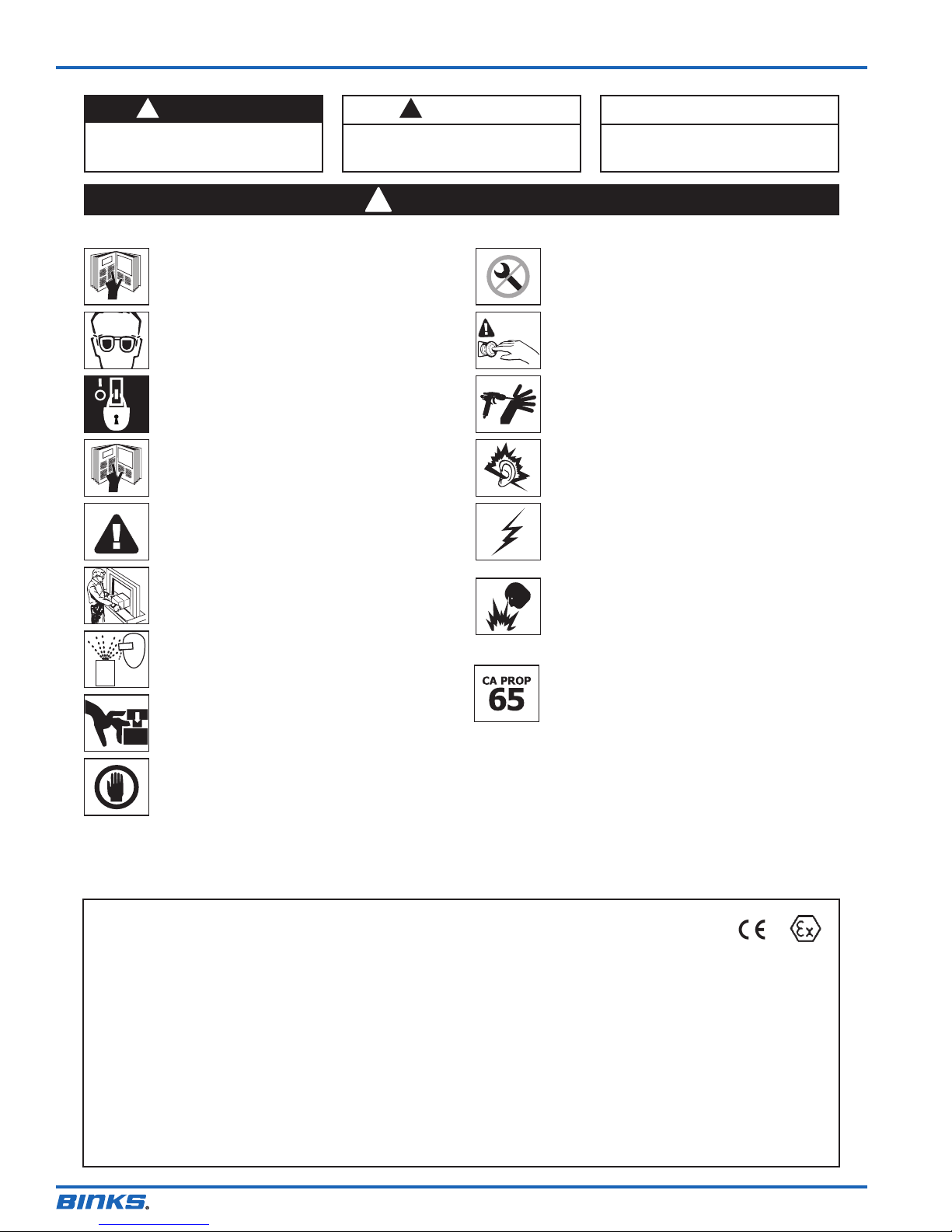
READ THE MANUAL
Before operating finishing equipment, read and understand all
safety, operation and maintenance information provided in the
operation manual.
WEAR SAFETY GLASSES
Failure to wear safety glasses with side shields could result in
serious eye injury or blindness.
DE-ENERGIZE, DEPRESSURIZE, DISCONNECT AND LOCK OUT ALL
POWER SOURCES DURING MAINTENANCE
Failure to De-energize, disconnect and lock out all power
supplies before performing equipment maintenance could cause
serious injury or death.
OPERATOR TRAINING
All personnel must be trained before operating finishing
equipment.
EQUIPMENT MISUSE HAZARD
Equipment misuse can cause the equipment to rupture,
malfunction, or start unexpectedly and result in serious injury.
KEEP EQUIPMENT GUARDS IN PLACE
Do not operate the equipment if the safety devices have been
removed.
PROJECTILE HAZARD
You may be injured by venting liquids or gases that are released
under pressure, or flying debris.
PINCH POINT HAZARD
Moving parts can crush and cut. Pinch points are basically any
areas where there are moving parts.
INSPECT THE EQUIPMENT DAILY
Inspect the equipment for worn or broken parts on a daily basis.
Do not operate the equipment if you are uncertain about its
condition.
NEVER MODIFY THE EQUIPMENT
Do not modify the equipment unless the manufacturer provides
written approval.
KNOW WHERE AND HOW TO SHUT OFF THE EQUIPMENT IN CASE
OF AN EMERGENCY
PRESSURE RELIEF PROCEDURE
Always follow the pressure relief procedure in the equipment
instruction manual.
NOISE HAZARD
You may be injured by loud noise. Hearing protection may be
required when using this equipment.
STATIC CHARGE
Fluid may develop a static charge that must be dissipated through
proper grounding of the equipment, objects to be sprayed and all
other electrically conductive objects in the dispensing area. Improper
grounding or sparks can cause a hazardous condition and result in
fire, explosion or electric shock and other serious injury.
PROP 65 WARNING
WARNING: This product contains chemicals known to the
State of California to cause cancer and birth defects or other
reproductive harm.
FIRE AND EXPLOSION HAZARD
Never use 1,1,1-trichloroethane, methylene chloride, other
halogenated hydrocarbon solvents or fluids containing such solvents
in equipment with aluminum wetted parts. Such use could result in
a serious chemical reaction, with the possibility of explosion. Consult
your fluid suppliers to ensure that the fluids being used are
compatible with aluminum parts.

EN
77-3027-R1.0 3 / 16
TYPES OF INSTALLATION
5/16" 1/4"
NOT RECOMMENDED
Only 34 PSI at gun inlet
25 feet of 1/4" I.D. hose causes
a drop of 26 PSI between the air
supply and the gun.
RECOMMENDED
48 PSI at gun inlet
25 feet of 5/16" I.D. hose causes
a drop of 12 PSI between the air
supply and the gun. For this
reason Binks recommends the use
of 5/16" hose.
WITH 60 PSI APPLIED AT AIR SUPPLY
AIR PRESSURE
Atomizing pressure must be set properly to allow for the drop in air pressure
between the regulator and the spray gun.
Cross section view
showing comparison of inside
hose diameters (actual size).
60 lbs. regulated pressure
An oil and water extractor
is important.
Achieving a fine spray finish without
the use of a good oil and water
extractor is virtually impossible.
A regulator/extractor serves a double
purpose. It eliminates blistering and
spotting by keeping air free of oil and
water, and it gives
precise air pressure
control at the gun.
Use DeVilbiss oil
and water extractors
and regulators.
See your local
distributor for
models.
Air pressure for atomization is regulated at the extractor. The flow of the fluid is adjusted by the fluid valve control
knob on gun, viscosity of paint and air pressure.
GRAVITY FEED HOOKUP
On gravity-feed spray guns the cup is located above the gun. The force of gravity pushes the fluid into the gun.
Advantages: this method offers quick color changes and convenience on small jobs or touch-up applications. Gravity
spray guns are able to use all of the coating—reducing waste.
Gravity
Feed Cup
Gun
Air
Air
Supply
Oil & Water
Extractor

EN
77-3027-R1.04 / 16
BINKS “TROPHY” SERIES GRAVITY SPRAY GUN
GRAVITY FEED GUN
ORIFICE SIZES
12 1.2 MM
14 1.4 MM
16 1.6 MM
18 1.8 MM
CUP DESIGNATION
0NO CUP
GGRAVITY CUP
2466 – XXXX – XXXX
NEEDLE MATERIAL
SSTAINLESS (HARDENED)
AIR CAP DESIGNATION
10 Series CONVENTIONAL
20 Series LVMP
30 Series HVLP
ATOMIZATION TECHNOLOGY
CN CONVENTIONAL
L V LVMP
HV HVLP
NUMBERING SYSTEM FOR FULL SIZE BINKS “TROPHY” SERIES GRAVITY SPRAY GUNS
Side port
adjusting valve
can be used as
an optional air
adjusting valve.
See charts on page 6 for complete gun assemblies.
NOTE
All gravity feed spray guns include
900cc aluminum cup (54-6106).

EN
77-3027-R1.0 5 / 16
ITEM
NO.
PART
NUMBER DESCRIPTION QTY.
1 54-6120 AIR CAP RETAINING RING
ASSEMBLY 1
5
SEE CHARTS
ON PAGE 7 AIR CAP
1
6 JGA-156-K10 SPRING-CLIP (KIT OF 10) 1
7SEE CHARTS
BELOW FLUID NOZZLE 1
8 54-6102-K3 BAFFLE/SEPARATOR (KIT OF 3) 1
9 54-6122 SIDE PORT VALVE ASSEMBLY 1
10 ------ +
6RETAINING CLIP 1
11 ------ +BODY BUSHING 1
12 ------ +
6O-RING 1
13 ------ +SIDE PORT STEM 1
14 ------ +
6PIN 1
15 54-6131-K AIR VALVE SERVICE KIT 1
16 ------ •FRONT SEAL – AIR VALVE 1
17 ------ •FRONT AIR VALVE SEAL 1
18 54-6109 AIR VALVE SPINDLE 1
19 ------ •AIR VALVE SPRING 1
20 ------ •REAR SEAL – AIR VALVE 1
21 SN-66 HOUSING 1
22 47-6825 NEEDLE – STAINLESS STEEL (STD.) 1
23 54-6133-K3 SPRING/PAD ASSEMBLY (KIT OF 3) 1
ITEM
NO.
PART
NUMBER DESCRIPTION QTY.
24 54-6111 KNOB – NEEDLE ADJUSTING 1
25 54-6130-K
NEEDLE PACKING KIT (STANDARD)
1
26 ------ nNUT – PACKING 1
27 ------ nSPRING FOR PACKING 1
28 ------ n
▼NEEDLE PACKING (STANDARD) 1
29 54-4360 TRIGGER 1
30 54-6132-K TRIGGER SCREW NUT KIT 1
31 ------ VTRIGGER SCREW 1
32 ------ VTRIGGER NUT 1
33 54-3513 SPINDLE CAP 1
34 SN-11 PLUG 1
35 54-6112 FITTING – AIR INLET 1
36 ------ GUN BODY WITH FLUID INLET 1
37 SPN-7 TOOL – SEAL INSERTION 1
38 ------ GUNNER'S MATE (3 CC BAG) 1
CHART 1: BINKS “TROPHY” SERIES GRAVITY SPRAY GUN PARTS LIST
CHART 3:
TEST AIR CAP KITS –
OPTIONAL
CONVENTIONAL
54-6141-K 12-C KIT
L V M P
54-6147-K 23-L KIT
HVLP
54-6152-K 32-H KIT – HVLP
CHART 2:
STAINLESS STEEL (HARDENED)
FLUID NOZZLES – STD.
STAINLESS FLUID NOZZLE
ORIFICE SIZE
FUID NOZZLE
PART NUMBER
.039" 1.0 mm 45-11050-10
.047" 1.2 mm 45-11050-12
.055" 1.4 mm 45-11050-14
.063" 1.6 mm 45-11050-16
.071" 1.8 mm 45-11050-18
+ PARTS INCLUDED IN
54-6122
nPARTS INCLUDED IN
54-6130-K
▼ALSO AVAILABLE IN KIT OF 3
SN-2-K3
•PARTS INCLUDED IN
54-6131-K
VPARTS INCLUDED IN
54-6132-K
6GTI-428-K5 SIDE PORT
REPAIR KIT

EN
77-3027-R1.06 / 16
BINKS “TROPHY” SERIES GRAVITY SPRAY GUN
NEEDLE AND NOZZLE SELECTION GUIDE
CHART 4: CONVENTIONAL GUN SET-UPS
TYPE OF FLUID
TO BE SPRAYED
COMPLETE
GUN ASSEMBLY
PART NUMBER
FLUID NOZZLE
AND AIR CAP
THIN
5-25 CENTIPOISE
15-19 sec. Zahn 2 cup
wash primers, dyes,
stains, solvents,
water, inks, sealers,
laquers, lubricants,
zinc chromates,
acrylics
2466-14CN-12SG 1.4 mm (.055") X 12C
2466-16CN-12SG 1.6 mm (.063") X 12C
MEDIUM
25-70 CENTIPOISE
20-30 sec. Zahn 2 cup
synthetic enamels,
varnishes, shellacs,
fillers, primers,
epoxies, urethanes,
lubricants,
wax emulsions,
enamels
2466-16CN-12SG 1.6 mm (.063") X 12C
2466-18CN-12SG 1.8 mm (.070") X 12C
CHART 6: HVLP GUN SET-UPS
TYPE OF FLUID
TO BE SPRAYED
COMPLETE
GUN ASSEMBLY
PART NUMBER
FLUID NOZZLE
AND AIR CAP
THIN
5-25 CENTIPOISE
15-19 sec. Zahn 2 cup
wash primers,
dyes, stains,
solvents, water,
inks, sealers,
laquers, lubricants,
zinc chromates,
acrylics
2466-12HV-32SG 1.2 mm (.047") X 32H
2466-14HV-32SG 1.4 mm (.055") X 32H
MEDIUM
25-70 CENTIPOISE
20-30 sec. Zahn 2 cup
synthetic enamels,
varnishes, shellacs,
fillers, primers,
epoxies, urethanes,
lubricants,
wax emulsions,
enamels
2466-14HV-32SG 1.4 mm (.055") X 32H
2466-18HV-32SG 1.8 mm (.070") X 32H
CHART 5: LVMP GUN SET-UPS
TYPE OF FLUID
TO BE SPRAYED
COMPLETE
GUN ASSEMBLY
PART NUMBER
FLUID NOZZLE
AND AIR CAP
THIN
5-25 CENTIPOISE
15-19 sec. Zahn 2 cup
wash primers,
dyes, stains,
solvents, water,
inks, sealers,
laquers, lubricants,
zinc chromates,
acrylics
2466-12LV-23SG 1.2 mm (.067") X 23L
2466-14LV-23SG 1.4 mm (.055") X 23L
MEDIUM
25-70 CENTIPOISE
20-30 sec. Zahn 2 cup
synthetic enamels,
varnishes, shellacs,
fillers, primers,
epoxies, urethanes,
lubricants,
wax emulsions,
enamels
2466-14LV-23SG 1.4 mm (.055") X 23L
2466-18LV-23SG 1.8 mm (.070") X 23L

EN
77-3027-R1.0 7 / 16
CHART 7: CONVENTIONAL AIR CAP AND FLUID NOZZLE SELECTION CHART
Air Cap Air Cap
Part No.
Spray Pattern
Range
CFM
@
30 PSI
CFM
@
50 PSI
CFM
@
70 PSI
Fluid Nozzle Typical Coatings
12-C 46-6501 4 – 12" 8.3 12.1 14.2 45-11050 series,
1.2 mm – 1.8 mm
Lacquers, Enamels, Top Coats,
Low Viscosity Adhesives
CHART 8: LVMP – LOW VOLUME MEDIUM PRESSURE AIR CAP AND FLUID NOZZLE SELECTION CHART
Air Cap Air Cap
Part No.
Spray Pattern
Range
CFM @30 PSI Gun Inlet
(Dynamic) Fluid Nozzle Typical Coatings
23-L 46-6511 4 – 12" 10.6 45-11050 series,
1.2 mm – 1.8 mm
Lacquers, Enamels, Top Coats,
Low Viscosity Adhesives
CHART 9: HVLP – HIGH VOLUME LOW PRESSURE AIR CAP AND FLUID NOZZLE SELECTION CHART
Air Cap Air Cap
Part No.
Spray Pattern
Range
SCFM @
10 PSI Cap
Pressure
(Dynamic)
Gun Inlet
PSI @ 10 PSI
at Air Cap
(Dynamic)
Fluid Nozzle Typical Coatings
32-H 46-6518 8 – 14" 15.5 26 45-11050 series,
1.2 mm – 1.8 mm
Lacquers, Enamels, Multi-Colors,
Multi-Spec, Nonstick Coatings,
Cut-Latex
CHART 10: ROUND SPRAY AIR CAP AND FLUID NOZZLE SELECTION CHART (OPTIONAL)
Air Cap Air Cap
Part No.
Spray Pattern
Range
CFM
@
30 PSI
CFM
@
50 PSI
CFM
@
70 PSI
Fluid Nozzle Typical Coatings
16 46-6505 2 – 4" 5.6 7.8 10.5 45-11050 series,
1.2 mm – 1.8 mm Lacquers, Enamels
BINKS “TROPHY” SERIES GRAVITY SPRAY GUN
AIR CAP AND FLUID NOZZLE SELECTION CHARTS

EN
77-3027-R1.08 / 16
INSTALLATION INSTRUCTIONS
For maximum transfer efficiency, do not use more pressure
than is necessary to atomize the material being applied.
NOTE
When using HVLP do not exceed inlet pressures
listed on page 7.
1. Connect the gun to a clean, moisture and oil free air
supply using a conductive hose of at least 5/16 in I.D.
NOTE
Depending on hose length, larger I.D. hose may be required. Install
an air gauge at the gun handle. See page 7 for operating pressures.
Do not use more pressure than is necessary to atomize the material
being applied. Excess pressure will create additional overspray and
reduce transfer efficiency.
NOTE
If quick connect couplings are required, use only high flow quick
connects approved for HVLP use. Other types will not flow
enough air for correct gun operation.
NOTE
If an air adjusting valve is used at the gun inlet, use HAV-501
adjusting valve.
OPERATION
GRAVITY MODELS
1. Mix coating material to manufacturer’s instructions and
strain material.
2. Fill the cup to no more than 3/4 inch from the top of the
cup. DO NOT OVERFILL.
3. Attach to cup lid.
4. Turn fluid adjusting knob (24) clockwise to prevent fluid
needle movement.
5. Turn sideport control (9) counter clockwise to fully open.
6. Adjust inlet air pressure if required.
7. Turn fluid adjusting knob counter clockwise until first
thread shows.
8. Test spray. If the finish is too dry, reduce airflow by
reducing air inlet pressure.
9. If finish is too wet, reduce fluid flow by turning fluid
adjusting knob (24) clockwise. If atomization is too
coarse, increase inlet air pressure. If too fine, reduce inlet
pressure.
10. The pattern size can be reduced by turning sideport
control (9) clockwise.
11. Hold gun perpendicular to surface being sprayed. Arcing
or tilting may result in uneven coating.
12. The recommended spray distance is 8 inches.
13. Spray edges first. Overlap each stroke a minimum of
75%. Move gun at a constant speed.
14. Always turn off air supply and relieve pressure when gun
is not in use.
PREVENTIVE MAINTENANCE
AND CLEANING
To clean air cap and fluid nozzle, brush exterior with a stiff
bristle brush. If necessary to clean cap holes, use a broom
straw or toothpick if possible. If a wire or hard instrument is
used, extreme care must be used to prevent scratching or
burring of the holes which will cause a distorted spray pattern.
To clean fluid passages, remove excess material from gun,
then flush with gun wash solution. Wipe the gun exterior with
a dampened cloth. Never completely immerse in any solvent
or cleaning solutions as this is detrimental to the lubricants
and life of the spray gun.
NOTE
When replacing the fluid nozzle (7) or fluid needle (22), replace
both at the same time. Using worn parts can cause fluid leakage.
See page 4. Also, replace the needle packing at this time. Torque
the fluid nozzle to 230–240 inch-lbs. Do not over tighten.
!
CAUTION
To prevent damage to fluid nozzle (7) or fluid needle (22), be sure
to either 1) pull the trigger and hold while tightening or loosening
the fluid nozzle, or 2) remove fluid adjusting knob (24) to relieve
spring pressure against needle collar.
GRAVITY CUP. Empty excess material and clean the cup.
Make sure the vent hole in the lid is clear.
NOTE
Before using the spray gun, flush it with solvent to ensure that
the fluid passages are clean.

EN
77-3027-R1.0 9 / 16
FIG.13
FIG.17
FIG.2
FIG.4
FIG.5
FIG.6
FIG.7
FIG.8
FIG.10
FIG.11
FIG.12
FIG.14
DISASSEMBLY
FIG.3
6mm
FIG.15
6mm
150 – 170 in-lbs
(16.9 – 19.2 Nm)
FIG.9
ASSEMBLY
FIG.16
FIG.1
NEEDLE AND VALVE DISASSEMBLY AND ASSEMBLY
REMOVAL AND INSTALLATION PROCEDURES

EN
77-3027-R1.010 / 16
MAINTENANCE – FLUID NOZZLE AND BAFFLE REMOVAL AND INSTALLATION
AIR CAP INDEX PIN (54-6184) INSTALLATION (OPTIONAL – 90° INCREMENTS INDEXING FEATURE)
FIG.1 FIG.2 FIG.3
FIG.1 FIG.2 FIG.3
FIG.4 FIG.5 FIG.6
FIG.7 FIG.8
3/8"
3/8"
230–240 in-lbs.
(25.9 – 27.1 Nm)
ALIGN SLOT
AND PIN

EN
77-3027-R1.0 11 / 16
MAINTENANCE – NEEDLE PACKING REMOVAL AND INSTALLATION
MAINTENANCE – SIDEPORT REMOVAL AND INSTALLATION
FIG.1
FIG.2 FIG.3
FIG.4 FIG.5
FIG.1 FIG.2 FIG.3
FIG.4 FIG.6
FIG.5
FIG.6
3/8"
3/8"
14 mm
14 mm

EN
77-3027-R1.012 / 16
CONDITION CAUSE CORRECTION
Heavy top or
bottom pattern
Horn holes plugged.
Obstruction on top or bottom of uid tip.
Cap and/or tip seat dirty.
Clean. Ream with non-metallic point.
Clean.
Clean.
Heavy right or left
side pattern
Left or right side horn holes plugged.
Dirt on left or right side of uid tip.
Clean. Ream with non-metallic point.
Clean.
Remedies for the top-heavy, bottom-heavy, right-heavy, and left-heavy patterns:
1. Determine if the obstruction is on the air cap or the uid tip. Do this by making a test
spray pattern. Then, rotate the cap one-half turn and spray another pattern. If the defect
is inverted, obstruction is on the air cap. Clean the air cap as previously instructed.
2. If the defect is not inverted, it is on the uid tip. Check for a ne burr on the edge of the
uid tip. Remove with #600 wet or dry sand paper.
3. Check for dried paint just inside the opening; remove by washing with solvent.
Heavy center pattern
Fluid ow too high for atomization air.
Material ow exceeds air cap's capacity.
Spreader adjustment valve set too low.
Atomizing pressure too low.
Material too thick.
Balance air pressure and uid ow. Increase
spray pattern width with spreader
adjustment valve.
Thin or lower uid ow.
Adjust.
Increase pressure.
Thin to proper consistency.
Split spray pattern
Atomization air pressure too high.
Fluid ow too low.
Spreader adjusting valve set too high.
Reduce at transformer or gun.
Increase uid ow (increases gun handling
speed).
Adjust.
Jerky or uttering spray
*Loose or damaged uid tip/seat.
Material level too low.
Container tipped too far.
Obstruction in uid passage.
Dry or loose uid needle packing nut.
Tighten or replace.
Rell.
Hold more upright.
Backush with solvent.
Lubricate or tighten.
Unable to get round
spray
Spreader adjustment screw not seating
properly.
Air cap retaining ring loose.
Clean or replace.
Tighten.
Will not spray
No air pressure at gun.
Fluid needle adjusting screw not open
enough.
Fluid too heavy for gravity feed.
Check air supply and air lines, blow out gun
air passages.
Open uid needle adjusting screw.
Thin material and/or change to larger tip size.
Paint bubbles in cup
Fluid tip not tight. Tighten tip.
Fluid leaking or
dripping from cup lid
Cup lid loose.
Dirty threads on cup or lid.
Cracked cup or lid.
Tighten lid.
Clean.
Replace cup and lid.
TROUBLESHOOTING
*Most common problem.

EN
77-3027-R1.0 13 / 16
CONDITION CAUSE CORRECTION
Starved spray pattern
Inadequate material ow.
Low atomization air pressure.
Back uid adjusting screw out to rst thread,
or change to larger tip size.
Increase air pressure and rebalance gun.
Excessive overspray
Too much atomization air pressure.
Gun too far from work surface.
Improper stroking (arcing, gun motion too
fast).
Reduce pressure.
Adjust to proper distance.
Move at moderate pace, parallel to work
surface.
Excessive fog
Too much or too fast-drying thinner.
Too much atomization (air pressure.)
Remix properly.
Reduce air pressure.
Dry spray
Air pressure too high.
Gun tip too far from work surface.
Gun motion too fast.
Gun out of adjustment.
Reduce air pressure.
Adjust to proper distance.
Slow down.
Adjust.
Fluid leaking from
packing nut
Packing nut loose.
Packing worn or dry.
Tighten, do not bind needle.
Replace or lubricate.
Fluid leaking or
dripping from front of
gun
Packing nut too tight.
Dry packing.
Fluid tip or needle worn or damaged.
Foreign matter in tip.
Fluid needle spring broken.
Wrong size needle or tip.
Adjust.
Lubricate.
Replace tip and needle.
Clean.
Replace.
Replace.
Fluid dripping or
leaking from bottom of
cup
Cup loose on gun.
Cup gasket worn or missing below cup.
Cup threads dirty.
Tighten.
Replace cup gasket.
Clean.
Runs and sags
Too much material ow.
Material too thin.
Gun tilted on an angle, or gun motion too
slow.
Adjust gun or reduce uid ow.
Mix properly or apply light coats.
Hold gun at right angle to work and adapt to
proper gun technique.
Thin, sandy coarse nish
drying before it ows
out
Gun too far from surface.
Too much air pressure.
Improper thinner being used.
Check distance. Normally approximately 8".
Reduce air pressure and check spray pattern.
Follow paint manufacturer's mixing
instructions.
Thick, dimpled nish
"orange peel"
Gun too close to surface.
Too much material coarsely atomized.
Air pressure too low.
Improper thinner being used.
Material not properly mixed.
Surface rough, oily, dirty.
Check distance. Normally approximately 8".
Follow paint manufacturer's mixing
instructions.
Increase air pressure or reduce uid ow.
Follow paint manufacturer's mixing
instructions.
Follow paint manufacturer's mixing
instructions.
Properly clean and prepare.
TROUBLESHOOTING

EN
77-3027-R1.014 / 16
HAV-500 OR HAV-501
Adjusting Valve
(HAV-501 SHOWN)
HAV-5 00 doe s n o t have
pressure gauge. Use to control
air usage at gun.
6-429 Binks
Gunners
Mate Lube
(Twenty
2 oz. bottles)
Compatible with all
paint materials; con-
tains no silicone or
petroleum distillates
to contaminate paint.
MSDS available upon
request.
HC-4419 Stem
1/4" NPT(F)
Gun End
HC-4719 Coupler
1/4" NPT(M)
Hose End
NIOSH-Certied, for respiratory protection
in atmospheres not immediately danger-
ous to life.
Small Medium Large
40-141 40-128 40-143
Millennium 3000
Twin Cartridge
PaintSprayRespirator
192212 Professional Spray Gun
Cleaning Kit
Contains six precision tools designed to eectively clean
all DeVilbiss, Binks, Finishline and other brand spray guns.
ACCESSORIES
HAF-507-K12
Whirlwind™
In-Line Air Filter
Kit of 12
Removes water, oil, and debris
from the air line.
Quick Connects for
HVLP Guns (Air)
High Flow Type
29-3100 Scrubs®
Hand Cleaner Towels
Scrubs®are a premoistened
handcleanertowelforpainters,
body men and mechanics that
go where you go and no water
is needed.
54-6106
1 Qt. Gravity Cup
(Aluminum)
DPC-60-K10
9oz Universal
x10
DPC-607
x2
DPC-59-K10
24oz Universal
x10
DPC-61-K10
34oz Universal
x10
DPC-606
x2
DPC-608
x2
DPC-22-K24
x24
DPC-6-K10
x10
DPC-44
DPC-31
DPC-66-K24
x24
DPC-67-K24
x24
DPC-42-K24
x24
DPC-65-K24
x24
9 FL
265 mL
DPC-602
x32
24 FL
710 mL
DPC-601
x32
34 FL
1000 mL
DPC-600
x32
125 µm
125 µm
200 µm
200 µm
DeKups®Accessories for gravity feed cups
SHELLS LINERS
192219
Gun Holder
Gun holder made to hold
guns with gravity cups.
KGP-13-K5
Cup Gasket
Fluid inlet gasket
necessary for use
with metal gravity
cups.

EN
77-3027-R1.0 15 / 16
NOTES

EN
77-3027-R1.016 / 16
)LQLVKLQJ%UDQGVUHVHUYHVWKHULJKWWRPRGLI\HTXLSPHQWVSHFL¿FDWLRQVZLWKRXW
prior notice. DeVilbiss, Ransburg, BGK, and Binks are registered trademarks of
Finishing Brands. ©2013 Finishing Brands. All rights reserved.
WARRANTY POLICY
%LQNVSURGXFWVDUHFRYHUHGE\)LQLVKLQJ%UDQGVRQH\HDUPDWHULDOVDQGZRUNPDQVKLSOLPLWHGZDUUDQW\7KH
XVHRIDQ\SDUWVRUDFFHVVRULHVIURPDVRXUFHRWKHUWKDQ)LQLVKLQJ%UDQGVZLOOYRLGDOOZDUUDQWLHV)RU
VSHFL¿FZDUUDQW\LQIRUPDWLRQSOHDVHFRQWDFWWKHFORVHVW)LQLVKLQJ%UDQGVORFDWLRQOLVWHGEHORZ
%LQNVLVSDUWRI)LQLVKLQJ%UDQGVDJOREDOOHDGHULQLQQRYDWLYHVSUD\¿QLVKLQJ
technologies. For technical assistance or to locate an authorized distributer,
FRQWDFWRQHRIRXULQWHUQDWLRQDOVDOHVDQGFXVWRPHUVXSSRUWORFDWLRQVEHORZ
USA/Canada
ZZZELQNVFRP
LQIR#¿QLVKLQJEUDQGVFRP
7HO
)D[
United Kingdom
ZZZ¿QLVKLQJEUDQGVHX
LQIR#¿QLVKLQJEUDQGVHX
7HO
)D[
China
ZZZ¿QLVKLQJEUDQGVFRPFQ
PNW#¿QLVKLQJEUDQGVFRPFQ
7HO
)D[
Mexico
ZZZ¿QLVKLQJEUDQGVFRPP[
VDOHV#¿QLVKLQJEUDQGVFRPP[
7HO
)D[
France
ZZZ¿QLVKLQJEUDQGVHX
LQIR#¿QLVKLQJEUDQGVHX
7HO
)D[
Japan
ZZZUDQVEXUJFRMS
ELQNVGHYLOELVV#UDQVEXUJFRMS
7HO
)D[
Brazil
ZZZGHYLOELVVFRPEU
7HO
)D[
Germany
ZZZ¿QLVKLQJEUDQGVHX
LQIR#¿QLVKLQJEUDQGVHX
7HO
)D[
Australia
ZZZ¿QLVKLQJEUDQGVFRPDX
VDOHV#¿QLVKLQJEUDQGVFRPDX
7HO
)D[
Table of contents
Other Binks Paint Sprayer manuals

Binks
Binks 2100 gw User manual

Binks
Binks TROPHY SERIES User manual

Binks
Binks EMG Series User manual

Binks
Binks MACH 1AR HVLP User manual

Binks
Binks 59-10001 A User manual

Binks
Binks Mag II User manual

Binks
Binks 460 User manual

Binks
Binks TROPHY AA 4400 User manual

Binks
Binks MX1212 User manual

Binks
Binks HP 4/32 User manual

Binks
Binks SV100 Installation guide

Binks
Binks STEADI-GRIP 80-295 User manual

Binks
Binks 80-295 User manual

Binks
Binks AA4400A User manual

Binks
Binks AA4000 User manual

Binks
Binks 95SL User manual

Binks
Binks MAVRICK User manual

Binks
Binks 7D User manual

Binks
Binks MX432 User manual

Binks
Binks sv50 User manual