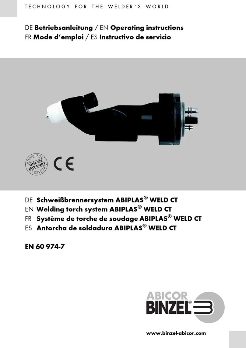
BINZEL-ABICOR MIG B 15 User manual

T E C H N O L O G Y F O R T H E W E L D E R ´ S W O R L D .
www.binzel-abicor.com
Z
E
R
T
I
F
I
Z
I
E
R
T
E
S
Q
M
-
S
Y
S
T
E
M
DIN EN
ISO 9001
DE Betriebsanleitung / EN Operating instructions
FR Mode d’emploi / ES Instructivo de servicio
DE MIG/MAG Schweißbrenner B
EN MIG/MAG Welding torch B
FR MIG/MAG Torches de Soudage B
ES MIG/MAG Antorcha de soldadura B
EN 60 974-7

DE - 2
Original Betriebsanleitung Schweißbrenner B
DE Original Betriebsanleitung
© Der Hersteller behält sich das Recht vor, jederzeit und ohne vorherige Mitteilung Änderungen an
dieser Betriebsanleitung durchzuführen, die durch Druckfehler, eventuelle Ungenauigkeiten der
enthaltenen Informationen oder Verbesserung dieses Produktes erforderlich werden. Diese
Änderungen werden jedoch in neuen Ausgaben berücksichtigt.
Alle in der Betriebsanleitung genannten Handelsmarken und Schutzmarken sind Eigentum der
jeweiligen Besitzer/Hersteller.
1 Bestimmungsgemäße
Verwendung DE-3
2 Technische Daten DE-3
3 Sicherheitshinweise DE-4
3.1 Warnhinweise DE-4
3.2 Angaben für den Notfall DE-4
4 Inbetriebnahme DE-5
4.1 Brenner ausrüsten DE-5
4.2 Drahtführung montieren DE-6
4.2.1 Führungsspirale DE-6
4.2.2 Kunststoffseele DE-6
4.3 Schlauchpaket anschließen DE-6
4.4 Schutzgasmenge einstellen DE-7
4.5 Draht einfädeln DE-7
5 Handgriff Bedienungs-
elemente DE-7
5.1 Taster 2-Takt Funktion DE-8
6 Betrieb DE-8
7 Außerbetriebnahme DE-8
8 Wartung und Reinigung DE-8

DE - 3
Schweißbrenner B 1 Bestimmungsgemäße Verwendung
1 Bestimmungsgemäße Verwendung
Die MIG/MAG Handschweißbrenner werden zum sicheren Schweißen von
niedrig- und hochlegierten Werkstoffen eingesetzt. Sie bestehen aus dem
Brennerhals mit Ausrüst- und Verschleißteilen, Handgriff oder Griffrohr und
Schlauchpaket mit Zentralstecker. Sie entsprechen der EN 60 974-7 und stellen
kein Gerät mit eigener Funktionserfüllung dar. Das Lichtbogenschweißen wird
erst in Verbindung mit der Schweißstromquelle möglich.
2 Technische Daten
Transport und Lagerung - 25 °C bis + 55°C
Relative Luftfeuchtigkeit bis 90 % bei 20 °C
Tab. 1 Umgebungsbedingungen im Betrieb
Spannungsart DC
Polung der Elektroden bei DC in der Regel positiv
Schutzgas (DIN EN 439) CO2 und Mischgas M21
Drahtarten handelsübliche Runddrähte
Spannungsbemessung 113 V Scheitelwert
Schutzart der maschinenseitigen Anschlüsse (EN 60 529) IP3X
Tab. 2 Allgemeine Brennerdaten (EN 60 974-7)
Typ Kühl-
art
Belastung ED Draht- Gasdurch-
fluss
Angaben zur Kühlung
Vorlauf-
temp.
Durch-
fluss
Fließdruck
CO2M21 max. min. min. max.
A A % mm l/min °C l/min bar bar
B 15 luft 180 150 60 0,6 - 1,0 10 - 18
B 24 luft 250 220 35 0.8 - 1.2 10 - 18
B 25 luft 230 200 60 0,8 - 1,2 10 - 18
B 36 luft 300 270 60 0,8 - 1,2 10 - 20
B 501 D flüssig 500 450 100 1,0 - 1,6 10 - 20 40 1 2,5 3,5
Tab. 3 Produktspezifische Brennerdaten (EN 60 974-7)

DE - 4
3 Sicherheitshinweise Schweißbrenner B
3 Sicherheitshinweise
Beachten Sie das beiliegende Dokument Sicherheitshinweise.
3.1 Warnhinweise
Die folgenden Warnhinweise stehen in dieser Betriebsanleitung vor potenziell
gefährlichen Arbeitsschritten. Nach abnehmendem Grad der Gefährdung
geordnet, bedeuten sie:
3.2 Angaben für den Notfall
Unterbrechen Sie im Notfall sofort folgende Versorgungen:
• Strom, Druckluft, Schutzgas
Weitere Maßnahmen entnehmen Sie der Betriebsanleitung der Stromquelle
oder der Dokumentation weiterer Peripheriegeräte.
Standardlänge L 3,00 m, 4,00 m, 5,00 m
Kühlmittelanschluss Stecknippel NW 5
Kühlgeräteleistung min. 800 W
Steuerleitung 2-adrig
Tab. 4 Schlauchpaket B
GEFAHR
Bezeichnet eine unmittelbar drohende Gefahr. Wenn sie nicht gemieden
wird, sind Tod oder schwerste Verletzungen die Folge.
WARNUNG
Bezeichnet eine möglicherweise gefährliche Situation. Wenn sie nicht
gemieden wird, können schwere Verletzungen die Folge sein.
VORSICHT
Bezeichnet eine möglicherweise schädliche Situation. Wenn sie nicht ge-
mieden wird, können leichte oder geringfügige Verletzungen die Folge sein.
HINWEIS
Bezeichnet die Gefahr, dass Arbeitsergebnisse beeinträchtigt werden oder
Sachschäden an der Ausrüstung die Folge sein können.

DE - 5
Schweißbrenner B 4 Inbetriebnahme
4 Inbetriebnahme
4.1 Brenner ausrüsten
Rüsten Sie den Brennerhals gemäß der folgenden Abbildung aus:
GEFAHR
Verletzungsgefahr durch unerwarteten Anlauf
Für die gesamte Dauer von Wartungs-, Instandhaltungs-, Montage- bzw.
Demontage- und Reparaturarbeiten ist folgendes zu beachten:
• Schalten Sie die Stromquelle aus.
• Sperren Sie die Gaszufuhr ab.
• Sperren Sie die Druckluftzufuhr ab.
• Ziehen Sie den Netzstecker.
VORSICHT
Verletzungsgefahr
Durchstich bzw. Einstich durch Drahtelektrode.
• Nicht in den Gefahrenbereich greifen und Schutzhandschuhe tragen.
1Typ B 15
2Gasverteiler
3Stromdüse
4Düsenstock
5Gasverteiler
6Brennerhals
7Typ B 501D
8Typ B 36
9Gasdüse
10 Typ B 25
Abb. 1 Brenner ausrüsten
12345
6
789
10

DE - 6
4 Inbetriebnahme Schweißbrenner B
4.2 Drahtführung montieren
4.2.1 Führungsspirale
Zur Verwendung von Stahldrähten.
1Schlauchpaket gestreckt auslegen, Gasdüse und Stromdüse von
Brennerhals abnehmen.
2Überwurfmutter am Zentralstecker abschrauben und Führungsspirale durch
Drahtförderschlauch bis Haltenippel einschieben.
3Überwurmutter wieder handfest aufschrauben und Überlänge von
Führungsspirale bündig am Brennerhals bzw. Düsenstock abschneiden.
4Überwurfmutter abschrauben und Führungsspirale herausziehen.
5Spiralenanfang im Winkel von ca. 40° anschleifen und Schnittkante
entgraten.
6Angespitzte Führungsspirale durch Drahtförderschlauch bis Haltenippel
einschieben, Überwurfmutter aufschrauben und mit Mehrfachschlüssel
festziehen.
7Stromdüse einschrauben und Gasdüse aufstecken.
4.2.2 Kunststoffseele
Zur Verwendung von Aluminium-, Kupfer, Nickel- und Edelstählen.
1Anfang der Kunststoffseele mit dem ABICOR BINZEL-Spitzer ca. 40°
anspitzen und Kunststoffseele durch den Drahtförderschlauch bis zum
spürbaren Anschlag in die Stromdüse schieben.
2Klemmnippel, O-Ring und Überwurfmutter auf die Kunststoffseele stecken
und unter Spannung die Überwurfmutter festschrauben.
3Überlange Kunststoffseele vor den Drahtförderrollen markieren und mit
dem ABICOR BINZEL-Cutter an der Markierung abschneiden.
4Schnittstelle anspitzen.
4.3 Schlauchpaket anschließen
1Zentralstecker an Zentralbuchse am Drahtvorschubgerät anschließen und
mit Anschlussmutter sichern.
2Anschlüsse für Kühlmittelvor-/-rücklauf, Schutzgas und Steuerleitungsstecker
fachgerecht montieren.
HINWEIS
• Bei Kunststoffseelen mit Aussendurchmesser 4,00 mm, muss das
Kapillarrohr im Zwischenanschluss durch ein Führungsrohr ersetzt
werden.

DE - 7
Schweißbrenner B 5 Handgriff Bedienungselemente
4.4 Schutzgasmenge einstellen
4.5 Draht einfädeln
1Draht in Drahtvorschubgerät nach Angaben des Herstellers einlegen.
2Drucktaster Stromloser Drahtvorschub an Drahtvorschubgerät betätigen,
bis Draht aus Stromdüse herausläuft.
5 Handgriff Bedienungselemente
Mit dem Standard Schweißbrenner ist die 2-Takt Betriebsart des Tasters
möglich. Weitere Betriebsarten und Handgriffmodule sind abhängig von der
jeweiligen Stromquelle und müssen separat bestellt werden.
HINWEIS
• Kontrollieren Sie die Mindestfüllmenge am Kühlgerät.
• Achten Sie darauf, dass Kühlmittelvor- und rücklauf ordnungsgemäß
installiert sind. Kühlmittelvorlauf = blau, Kühlmittelrücklauf = rot.
• Verwenden Sie kein deionisiertes oder demineralisiertes Wasser als
Kühlmittel oder für Dichtheits- und Durchflussprüfungen.
Dies kann die Lebensdauer Ihres Schweißbrenners beeinträchtigen.
• Wir empfehlen für flüssiggekühlte Schweißbrenner die Verwendung von
ABICOR BINZEL Kühlmittel der Reihe BTC.
• Bei jeder Erstinbetriebnahme bzw. nach jedem Schlauchpaketwechsel
müssen Sie das Kühlsystem entlüften: Kühlmittelrücklauf von
Umlaufkühlgerät lösen, über Auffangbehälter halten. Öffnung am
Kühlmittelrücklauf verschließen. Durch wiederholtes, abruptes Öffnen
wieder frei geben, bis Kühlmittel kontinuierlich und blasenfrei fließt.
HINWEIS
• Art und Menge des zu verwendenden Schutzgases hängt von der
Schweißaufgabe und der Gasdüsengeometrie ab.
• Stellen Sie alle Schutzgasverbindungen gasdicht her.
• Um eine Verstopfung durch Verunreinigung in der Schutzgasversorgung
zu verhindern, müssen Sie das Flaschenventil vor dem Anschluss kurz
öffnen. Dadurch werden evtl. Verunreinigungen ausgeblasen.
HINWEIS
• Beachten Sie die Betriebsanleitungen der schweißtechnischen
Komponenten z.B. Schweißstromquelle.

DE - 8
6 Betrieb Schweißbrenner B
5.1 Taster 2-Takt Funktion
1Taster am Handgriff drücken und halten = Schweißstart.
2Taster lösen = Schweißende.
6 Betrieb
1Schutzgasflasche öffnen.
2Stromquelle einschalten.
3Schweißparameter einstellen.
4Schweißstart.
7 Außerbetriebnahme
1Schweißende.
2Schutzgas-Nachströmzeit abwarten und Stromquelle ausschalten.
3Ventil der Schutzgasflasche schließen.
8 Wartung und Reinigung
HINWEIS
• Flüssiggekühlte Schlauchpakete werden bei Überhitzung undicht. Lassen
Sie deshalb das Kühlgerät nach dem Schweißen ca. 5 min. weiter laufen.
GEFAHR
Verletzungsgefahr durch unerwarteten Anlauf
Für die gesamte Dauer von Wartungs-, Instandhaltungs-, Montage- bzw.
Demontage- und Reparaturarbeiten ist folgendes zu beachten:
• Schalten Sie die Stromquelle aus.
• Sperren Sie die Gaszufuhr ab.
• Sperren Sie die Druckluftzufuhr ab.
• Ziehen Sie den Netzstecker.

DE - 9
Schweißbrenner B 8 Wartung und Reinigung
1Schlauchpaket maschinenseitig lösen und in gestreckte Position bringen.
2Überwurfmutter abschrauben und Führungsspirale bzw. Kunststoffseele
herausziehen, ggf. austauschen.
3Verschleißteile am Brennerhals entfernen.
4Drahtförderschlauch von beiden Seiten mit Pressluft ausblasen.
5Führungsspirale bzw. Kunststoffseele montieren und mit Überwurfmutter
sichern.
6Schlauchpaket maschinenseitig mit Drahtvorschubgerät verbinden.
HINWEIS
• Die angegebenen Wartungsintervalle sind Richtwerte und beziehen sich
auf den Einschichtbetrieb.
• Wartungs- und Reinigungsarbeiten dürfen nur von qualifizierten und
ausgebildeten Fachkräften durchgeführt werden.
• Kühlmittelschläuche, Dichtungen und Anschlüsse auf Schäden und
Dichtheit prüfen, ggf. austauschen.
• Tragen Sie während der Wartungs- und Reinigungsarbeiten immer Ihre
persönliche Schutzausrüstung.
WARNUNG
Verletzungsgefahr
Schwere Verletzung durch herumwirbelnde Teile.
• Tragen Sie beim Ausblasen der Drahtführung persönliche
Schutzausrüstung, insbesondere eine Schutzbrille.

EN - 2
English Translation of the original operating instructions Welding torch B
EN English Translation of the original operating instructions
© The manufacturer reserves the right, at any time and without prior notice, to make such changes
and amendments to these Operation Instructions which may become necessary due to misprints,
inaccuracies or improvements to the product. Such changes will however be incorporated into
subsequent editions of the Instructions. All trademarks mentioned in the operating instructions are
the property of their respective owners.
All brand names and trademarks that appear in this manual are the property of their respective
owners/manufacturers.
1 Designated use EN-3
2 Technical data EN-3
3 Safety instructions EN-4
3.1 Warnings EN-4
3.2 Emergency information EN-4
4 Putting into operation EN-5
4.1 Setting up the torch EN-5
4.2 Mounting the wire guide EN-6
4.2.1 Liner EN-6
4.2.2 PA liner EN-6
4.3 Connecting the cable assembly EN-6
4.4 Setting the shielding gas volume EN-7
4.5 Feeding in wire EN-7
5 Handle operating elements EN-7
5.1 Two-cycle trigger function EN-8
6 Operation EN-8
7 Putting out of operation EN-8
8 Maintenance and cleaning EN-8

EN - 3
Welding torch B 1 Designated use
1 Designated use
MIG/MAG manual welding torches are used to safely weld low and high-
alloy materials. They consist of the torch neck with equipment parts and wear
parts, handle or handle tube and cable assembly with central connector. They
conform to EN 60 974-7 and are not considered devices that independently
fulfil functions. Arc welding can only be carried out in connection with a
welding power source.
2 Technical data
Transport and storage -25°C to 55°C
Relative humidity Up to 90% at 20°C
Tab. 1 Ambient conditions during operation
Type of voltage DC
DC polarity of the electrodes Usually positive
Shielding gas (DIN EN 439) CO2and mixed gas M21
Wire types Commercially available round
wires
Voltage rating Peak value of 113 V
Protection type of the machine-side connections
(EN 60 529)
IP3X
Tab. 2 General torch data (EN 60 974-7)
Type Type of
cooling
Load DCY Wire Gas flow Cooling data
Supply
temp.
Flow Flow
pressure
CO2M21 Max. Min. Min. Max.
A A % mm l/min °C l/min bar bar
B 15 Air 180 150 60 0.6 - 1.0 10 - 18
B 24 Air 250 220 35 0.8 - 1.2 10 - 18
B 25 Air 230 200 60 0.8 - 1.2 10 - 18
B 36 Air 300 270 60 0.8 - 1.2 10 - 20
B 501 D Liquid 500 450 100 1.0 - 1.6 10 - 20 40 1 2.5 3.5
Tab. 3 Product-specific torch data (EN 60 974-7)

EN - 4
3 Safety instructions Welding torch B
3 Safety instructions
The attached safety instructions must be observed.
3.1 Warnings
In these operating instructions, potentially hazardous work steps are preceded
by the following warnings. Arranged in descending order of danger, they
mean:
3.2 Emergency information
In the event of an emergency, immediately disconnect the following supplies:
• Electricity, compressed air, shielding gas
Further measures can be found in the operating instructions for the power
source or the documentation for other peripheral devices.
Standard length L 3.00 m, 4.00 m, 5.00 m
Coolant connection Plug-in nipple, nom. diam. 5
Cooling unit power Min. 800 W
Control lead 2-core
Tab. 4 Cable assembly B
DANGER
Describes an imminent threatening danger. If not avoided, it will result in
fatal or extremely critical injuries.
WARNING
Describes a potentially dangerous situation. If not avoided, it may result in
serious injuries.
CAUTION
Describes a potentially harmful situation. If not avoided, it may result in slight
or minor injuries.
NOTICE
Describes the risk of impairing work results or potential material damage to
the equipment.

EN - 5
Welding torch B 4 Putting into operation
4 Putting into operation
4.1 Setting up the torch
Set up the torch neck according to the following figure:
DANGER
Risk of injury due to unexpected start-up
The following instructions must be adhered to throughout all maintenance,
servicing, assembly, disassembly and repair work:
• Switch off the power source.
• Close the gas supply.
• Close the compressed air supply.
• Disconnect the mains plug.
CAUTION
Risk of injury
Puncture or cut-in wounds may be caused by the wire electrode.
• Wear protective gloves and never reach into the danger zone.
1Type B 15
2Gas diffuser
3Contact tip
4Tip adaptor
5Gas diffuser
6Torch neck
7Type B 501D
8Type B 36
9Gas nozzle
10 Type B 25
Fig. 1 Setting up the torch
12345
6
789
10

EN - 6
4 Putting into operation Welding torch B
4.2 Mounting the wire guide
4.2.1 Liner
For using steel wires.
1Stretch out the cable assembly and remove the gas nozzle and contact tip
from the torch neck.
2Unscrew the nut from the central connector and slide the liner through the
wire conduit up to the retaining nipple.
3Tighten the nut again by hand and cut off any excess liner flush with the
torch neck or tip adaptor.
4Unscrew the nut and pull out the liner.
5Sharpen the start of the liner to an angle of approx. 40° and deburr the
edge.
6Slide the sharpened liner through the wire conduit up to the retaining nipple
then screw down the nut and tighten it using a switch key wrench.
7Screw in the contact tip and attach the gas nozzle.
4.2.2 PA liner
For using aluminium, copper, nickel and stainless steels.
1Use the ABICOR BINZEL sharpener to sharpen the start of the PA liner to
an angle of about 40°. Then slide the PA liner through the wire conduit until
you feel it reach the contact tip.
2Slide the clamp nipple, O-ring and nut onto the PA liner and tighten the nut
under tension.
3Mark any excess length of PA liner in front of the wire feed rolls and use the
ABICOR BINZEL cutter to cut it off at the mark.
4Sharpen the cutting point.
4.3 Connecting the cable assembly
1Attach the central connector to the central socket on the wire feed unit and
secure it with the connection nut.
2Properly mount the connections for coolant supply/return, shielding gas
and the control lead plug.
NOTICE
• For PA liners with an outer diameter of 4.00 mm, the capillary tube in the
distance adaptor must be replaced with a guide tube.

EN - 7
Welding torch B 5 Handle operating elements
4.4 Setting the shielding gas volume
4.5 Feeding in wire
1Insert the wire into the wire feed unit as specified by the manufacturer.
2Press the ‘zero-current wire feed’ trigger on the wire feed unit until the wire
emerges from the contact tip.
5 Handle operating elements
The trigger’s two-cycle mode can be activated when using a standard welding
torch. Further operating modes and handle modules depend on the
corresponding welding power source and must be ordered separately.
NOTICE
• Check the minimum fill level on the cooling unit.
• Ensure that the coolant supply and return hoses have been correctly
installed. Coolant supply = blue, coolant return = red.
• Do not use deionised or demineralised water as coolant or for leak and
flow tests. This may shorten your welding torch’s service life.
• For liquid-cooled welding torches, we recommend using
ABICOR BINZEL BTC coolant.
• The cooling system must be purged of any air each time the device is
commissioned and after every cable assembly change: disconnect the
coolant return hose from the coolant recirculator and hold it over a
collection receptacle. Close the opening on the coolant return hose then
re-open it by abruptly releasing it. Repeat until the coolant flows into the
collection receptacle continuously and without air bubbles.
NOTICE
• The type and amount of shielding gas used depend on the welding task
and the gas nozzle geometry.
• Make all shielding gas connections gas-tight.
• To prevent the shielding gas supply from becoming clogged by
impurities, the cylinder valve must be opened briefly before connecting
the cylinder. This will expel any impurities that may be present.
NOTICE
• Please also consult the operating instructions for the welding
components, e.g. the welding power source.

EN - 8
6 Operation Welding torch B
5.1 Two-cycle trigger function
1Press and hold the trigger on the handle = start welding.
2Release the trigger = stop welding.
6 Operation
1Open the shielding gas cylinder.
2Switch on the power source.
3Set the welding parameters.
4Start welding.
7 Putting out of operation
1Stop welding.
2Wait until the shielding gas post-flow time has passed and then switch off
the power source.
3Close the valve on the shielding gas cylinder.
8 Maintenance and cleaning
NOTICE
• As liquid-cooled cable assemblies start to leak when they overheat, the
cooling unit should continue running for approx. 5 min. after welding.
DANGER
Risk of injury due to unexpected start-up
The following instructions must be adhered to throughout all maintenance,
servicing, assembly, disassembly and repair work:
• Switch off the power source.
• Close the gas supply.
• Close the compressed air supply.
• Disconnect the mains plug.

EN - 9
Welding torch B 8 Maintenance and cleaning
1Unscrew the cable assembly on the machine side and lay it out in a
stretched position.
2Unscrew the nut and pull out the liner or PA liner and replace it, if necessary.
3Remove wear parts from the torch neck.
4Clean the wire conduit from both sides with compressed air.
5Mount the liner or PA liner and secure with the nut.
6Connect the cable assembly on the machine side to the wire feed unit.
NOTICE
• The specified maintenance intervals are guidance values and refer to
single-shift operation.
• Maintenance and cleaning work may only be carried out by qualified
and trained specialists.
• Check the coolant hose, seals and connectors for damage or leaks and
replace if necessary.
• Always wear your personal protective equipment when performing
maintenance and cleaning work.
WARNING
Risk of injury
Serious injuries can be caused by parts swirling around.
• When cleaning the wire guide with compressed air, always wear
personal protective clothing, in particular safety goggles.

FR - 2
Traduction des instructions de service d'origine Torche de soudage B
FR Traduction des instructions de service d'origine
© Le constructeur se réserve le droit de modifier ce mode d´emploi à tout moment et sans avis
préalable pour des raisons d’erreurs d’impression, d’imprécisions éventuelles des informations
contenues ou d’une amélioration de ce produit. Toutefois, ces modifications ne seront prises en
considération que dans de nouvelles versions des instructions de service.
Toutes les marques déposées et marques commerciales contenues dans le présent mode d'emploi
sont la propriété de leurs titulaires/fabricants respectifs.
1 Utilisation conforme aux
dispositions FR-3
2 Caractéristiques techniques FR-3
3 Consignes de sécurité FR-4
3.1 Mises en garde FR-4
3.2 Instructions concernant les
situations d'urgence FR-4
4 Mise en service FR-5
4.1 Équipement des torches FR-5
4.2 Montage de l'amenée de fil FR-6
4.2.1 Gaine guide fil FR-6
4.2.2 Gaine guide fil synthétique FR-6
4.3 Raccordement du faisceau FR-7
4.4 Réglage de la quantité de gaz de
protection FR-7
4.5 Enfilage du fil FR-7
5 Poignée éléments de comman
de FR-8
5.1 Bouton avec 2 modes de
fonctionnement FR-8
6 Fonctionnement FR-8
7 Mise hors service FR-8
8 Maintenance et nettoyage FR-9

FR - 3
Torche de soudage B 1 Utilisation conforme aux dispositions
1 Utilisation conforme aux dispositions
Les torches manuelles de soudage MIG/MAG sont utilisées pour le soudage
de matériaux faiblement et fortement alliés. Elles sont composées d'un col de
cygne avec ses pièces détachées et d'usure, poignée ou tube de poignée et
faisceau avec bloc arrière. Elles sont conformes aux exigences de la directive
EN 60 974-7 et ne sont pas des appareils autonomes. Pour lancer un processus
de soudage à l'arc, une source de courant de soudage doit être connectée.
2 Caractéristiques techniques
Transport et stockage -25 °C à +55 °C
Humidité relative de l'air jusqu'à 90 % à 20 °C
Tab. 1 Conditions environnementales pendant l'exploitation
Type de tension CC
Polarité des électrodes pour CC normalement positive
Gaz de protection (DIN EN 439) CO2 et gaz mixte M21
Types de fil fils de section circulaire standard
Gamme de tension valeur maximum 113 V
Classe de protection des raccords côté poste (EN 60 529) IP3X
Tab. 2 Caractéristiques générales (EN 60 974-7)
Type Type de
refroidis-
sement
Capacité F.d.m fil Débitde
gaz
Données de refroidissement
Tempéra-
ture de
départ
Débit Pression
d'écoulement
CO2M21 max. min. min. max.
A A % mm l/min °C l/min bar bar
B 15 air 180 150 60 0,6 - 1,0 10 - 18
B 24 air 250 220 35 0.8 - 1.2 10 - 18
B 25 air 230 200 60 0,8 - 1,2 10 - 18
B 36 air 300 270 60 0,8 - 1,2 10 - 20
B 501 D liquide 500 450 100 1,0 - 1,6 10 - 20 40 1 2.5 3.5
Tab. 3 Caractéristiques spécifiques (EN 60 974-7)

FR - 4
3 Consignes de sécurité Torche de soudage B
3 Consignes de sécurité
Respectez les consignes de sécurité figurant dans le document joint à ce
manuel.
3.1 Mises en garde
Dans ce mode d'emploi, les mises en garde suivantes sont placées avant les
étapes de travail potentiellement dangereuses. Elles sont classées par ordre
d'importance décroissant et ont la signification suivante :
3.2 Instructions concernant les situations d'urgence
En cas d'urgence, coupez immédiatement les alimentations suivantes :
• Courant électrique, air comprimé, gaz de protection
D'autres mesures sont décrites dans le mode d'emploi de la source de courant
ou dans la documentation des dispositifs périphériques supplémentaires.
Longueur standard L 3,00 m, 4,00 m, 5,00 m
Raccordement du liquide de
refroidissement
Raccord rapide standard, diamètre 5 mm
Puissance du refroidisseur min. 800 W
Câble de commande à 2 conducteurs
Tab. 4 Faisceau B
DANGER
Signale un danger imminent qui, s'il n'est pas évité, entraîne des blessures
corporelles extrêmement graves ou la mort.
AVERTISSEMENT
Signale une situation éventuellement dangereuse qui, si elle n'est pas évitée,
peut entraîner des blessures graves.
ATTENTION
Signale un risque éventuel qui, s'il n'est pas évité, peut entraîner des
blessures légères ou mineures.
AVIS
Signale le risque d'obtenir un résultat de travail non satisfaisant et des
dommages matériels.
This manual suits for next models
9
Table of contents
Languages:
Other BINZEL-ABICOR Welding System manuals