BIO UV UV10 User manual

BIO-UV
Copyright BIO-UV 03/07/08 1
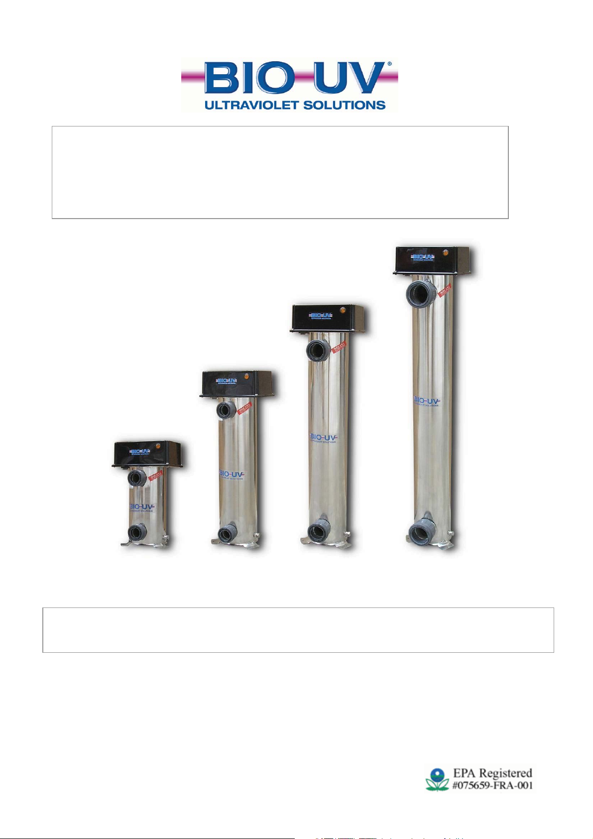
UV10 UV20 UV30 UV40
Société BIO-UV SA
ZAC La Petite Camargue
34400 LUNEL France
Hotline : + 33 (0)890 71 03 70 (0,15€/min)
www.bio-uv.com Email : info@bio-uv.com
BIO
-
UV range
for Swimming pools and Spas
INSTALLATION AND USE
R MANUAL

BIO-UV
Copyright BIO-UV 03/07/08 2
CERTIFICAT DE CONFORMITE
CERTIFICATE OF CONFORMITY
Ce certificat confirme que tous les appareils conçus et fabriqués par la
société BIO-UV SA depuis le 01/06/2000 sont conformes a toutes les
directives CEE particulièrement en matière de directives C.E.M et
Electriques.
This certificate confirm that all products manufactured by BIO-UV SA for sale after
June 2000 will comply with the requirements of all relevant EEC directives.
Specifically these include the E.M.C directive.
Benoît GILLMANN
Chairman and Managing Director of BIO-UV
Société BIO-UV SA
ZAC La Petite Camargue
34400 LUNEL France
Hotline : + 33 (0)890 71 03 70 (0,15€/min)
www.bio-uv.com Email : info@bio-uv.com

BIO-UV
Copyright BIO-UV 03/07/08 3
We thank you for choosing a BIO-UV ultraviolet water treatment system.
Our equipment has been designed to offer you operational reliability in total confidence
for many years.
CONTENTS
Page
Warnings and safety 4
Exploded view 5
Detailof the parts 6
Parts list 7
Dimensions 7
Standard installation 8
Electrical Connections 9
Wiring Diagram 11
Maintenance 12
Guarantees 13
DESCRIPTION UV 10 UV 20 UV 30 UV 40
Maximum pressure in Use 3Bar 3Bar 3Bar 3Bar
Maximum flow rate (m3/h)
(after pressure losses) 7 12 20 28
EXPOSITION TIME / secondes 2,8” 2,6” 2,3 2,1
PERFORMANCE In millijoules at the actual flow
rates recommended above.
(mandatory standard for drinking water: 25mj)
25 mJ 25 mJ 25 mJ 25 mJ
BALLAST 1111
LAMP (nomber and power) 1 x 33 W 1 x 55 W 1 x 87 W 1 x 114 W
SERVICE LIFE of LAMPS 13 000 h 13 000 h 13 000 h 13 000 h
DIMENSION of the UV CHAMBERS in cm 32 58 83 108
DIAMETER of the UV CHAMBERS in cm 15 15 15 15
OVERALL HEIGHT in cm 42 69 94 120
WEIGHT POIDS (without water) kg 7,6 9 11 14
CAPACITY IN LITRES 6,40 11,70 17,30 22,40
INPUT/OUTPUT (diameter in mm)
with Unions supplied 50 50 63 75
The BIO-UV equipment is ready to be installed.
No intervention is required inside the equipment.
A simplified quick assembly procedure is provided.

BIO-UV
Copyright BIO-UV 03/07/08 4
Safety Warning
NEVER LOOK AT THE ULTRAVIOLET LAMP WHEN LIT WITHOUT USING PROTECTIVE
GOGGLES AS IT COULD CAUSE SEVERE INJURIES, BURNS OR EVEN BLINDNESS.
NEVER UNDO THE STAINLESS STEEL TIGHTENING NUT WITH THE FILTRATION
RUNNING, AS THE QUARTZ SLEEVE COULD BE EXPELLED FROM ITS HOLDER AT
SPEED AND INJURE YOU
Before attempting to access the connection terminals, all power supplies should be
disconnected. If the cable is damaged, it must be replaced by a cable or special assembly
available from the after-sales service.
For your safety as an installer and/or user:
1. Read all the instructions in this manual before switching on the
BIO-UV sterilizer
2. WHEN REPLACING THE LAMPS AND/OR DURING THE ANNUAL CLEANING OF QUARTZ
SLEEVES, CHECK THAT THE ELECTRICAL PART IS IN PLACE AND CORRECTLY SECURED
BEFORE SWITCHING ON THE STERILIZER.
3. CHECK THAT THE NUT, WASHER AND O-RING (16-15-14) ARE CORRECTLY POSITIONED,
OTHERWISE THE QUARTZ SLEEVES COULD BE EXPELLED FROM THEIR HOLDER AT SPEED
AND INJURE YOU.
4. In order to avoid electrical short-circuits, never submerge electrical wires or the BIO-UV sterilizer
in the pool water or any other liquid
5. Disconnect the BIO-UV sterilizer before all maintenance and cleaning operations
6. Allow the ultraviolet lamps to cool before handling
7. DO not touch the ultraviolet lamps with bare hands. It would leave dirt on the lamps
which would reduce their service life. If you touch them, clean them using methylated
spirits or spirit vinegar
8. Do not operate the BIO-UV sterilizer if the power supply lead is damaged
9. Do not re-start the system without first checking that the electrical part and the sterilizer’s upper
unit are correctly back in place
10. Do not use the BIO-UV sterilizer for any other purpose than that for which it was designed

BIO-UV
Copyright BIO-UV 03/07/08 5
Sterilizer – Exploded view

BIO-UV
Copyright BIO-UV 03/07/08 6
Details of the parts of UV range Sterilizers

BIO-UV
Copyright BIO-UV 03/07/08 7
Parts List
N° Qty Reference Designation
1 1 UI-1-005 A Top
2 1 UI-1-010 Body
3 2 UI-1-015 Sleeve
4 1 UI-1-017 Sleeve purge
5 1 UI-1-018 B Bottom
6 1 UI-1-023 Purge plug
7 1 UI-1-024 Terminal
8 1 UI-2-004 Support Guide
9 1 UI-2-008 Plug 14x
10 1 UI-2-009 Plug 14
11 1 UI-3-004 Quartz tube
12 1 UI-3-008 UV-C lamp
13 1 UI-4-004 Tip
14 1 UI-4-005 O-ring joint
15 1 UI-4-007 Washer
16 1 UI-4-009 Stainless steel nut
17 1 UI-5-002 Ballast
18 1 UI-5-003 Switch
19 1 UI-5-004 Padding
20 1 UI-5-005 Lamp operating indicator light
21 1 UI-5-071 Socket
22 1 UI-6-004 Cover
Dimensions
DIMENSIONS OF THE UV-RANGE Sterilizers in mm (except K)
Type A B C D E F G H I J K
UV 10 424 256 173 83 313 154 235 115 249 174 1"1/2
UV 20 694 525 443 83 583 154 235 115 249 174 1"1/2
UV 30 934 721.5 689 83 829 154 235 115 249 174 2"
UV 40 1194 1026 943 83 1083 154 235 115 249 174 2"1/2

BIO-UV
Copyright BIO-UV 03/07/08 8
Standard Installation
RECOMMANDATIONS
Install the BIO-UV equipment in the equipment room, respecting the 0.1 and 2 safety areas around the
volume in accordance with the current installation rules (NF C15100)
Unless the equipment is dismantled in order to change the lamps and clean the quartz sleeves,
leave enough room to remove the lamps – the AVAILABLE HEIGHT in the equipment
room must be DOUBLE the total size of the equipment
The BIO-UV equipment must be installed on the discharges after the filter and before the
heater (where applicable).
The equipment’s water inlet should preferably be at the bottom and, thus, its outlet to the pool at the top.
(If necessary it can be positioned horizontally).
The unions provided for ease of fitting and dismantling are supplied with either a 50 mm (UV10 & 20),
63 mm (UV30) or 75 mm diameter (UV40).
If a bypass is used for the heating, the BIO-UV equipment should be installed before the bypass
Using clamping collars (50, 63 or 75 mm diameter)secure the REMANENT and pH liquid injectors and pH
analysis probe in the correct order, see diagram above.
BIO-UV
DOSING
PUMP
INJECTION
BIO-UV
pH
REGULAT
OR
BY-PASS VALVE
BY-PASS VALVE
BY-PASS VALVE
Ø50 ou 63 ou 75 UNION
pH
PROBE
HEATING
FILTRE
SWIMMIN
G POOL
PUMP
BIO-UV

BIO-UV
Copyright BIO-UV 03/07/08 9
ELECTRICAL CONNECTIONS
IMPORTANT
The connections must be made by a qualified technician.
A 30mA differential circuit breaker must be present and a fuse or a circuit breaker
must be installed.
The power supply must correspond to that shown on the label on the side of the
equipment.
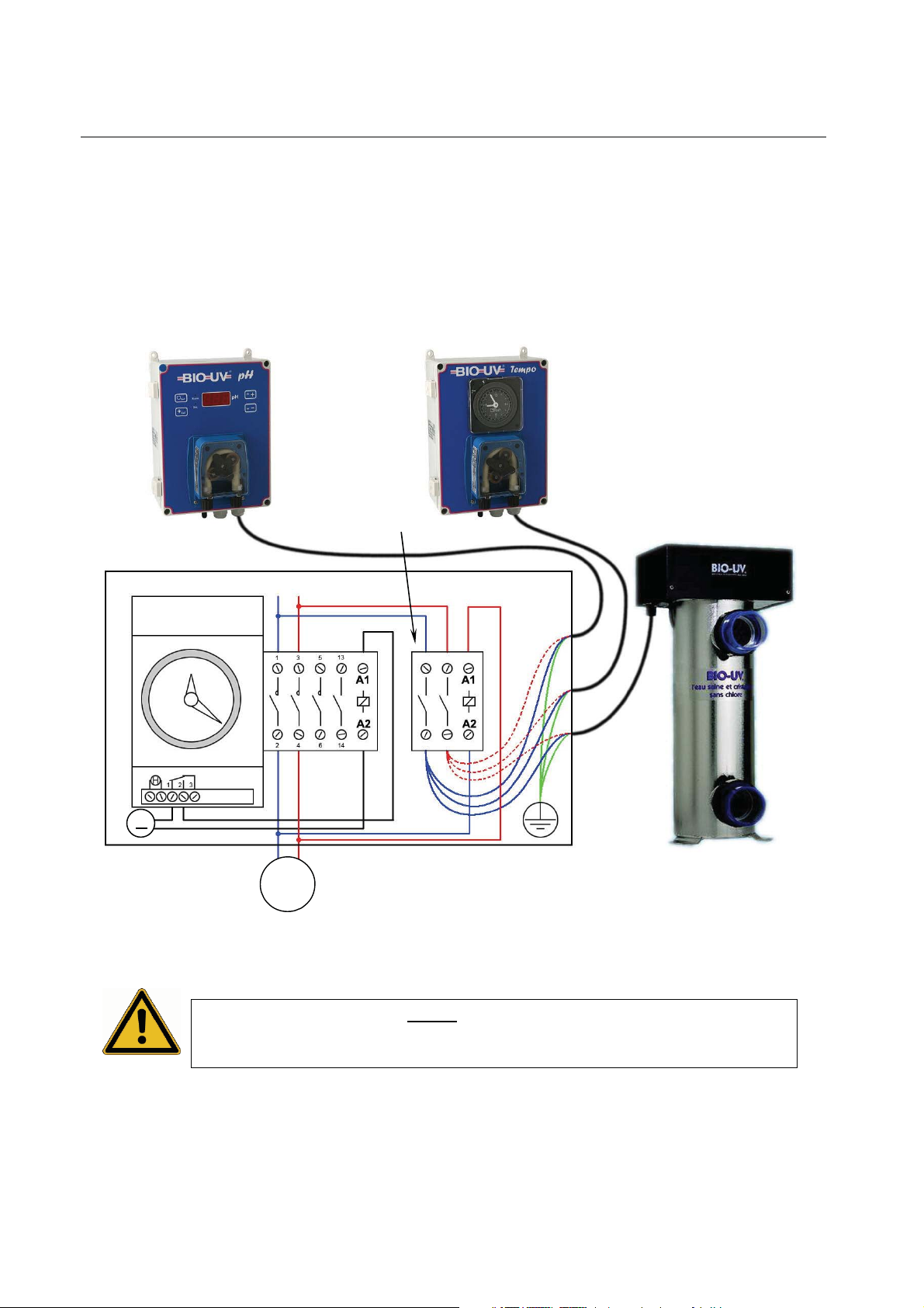
The power supplied to the pH regulator must be servo-controlled by the filtration.
(See wiring diagram below).
Before making the connections, switch off the power supplies.
1°/ General case : you have a contactor with a coil supplied with 220-240Vac :
Connect the UV reactor to the filtration unit as shown below:
• Connect the UV reactor to the contactor coil.
• Check that the fuse or circuit breaker is appropriate for the power of all the
connected equipment.
The UV reactor must never be connected to the same terminal
strip as the filtration pump(s) and/or to the boosters in your
system.
Earth
= Green/Yellow
Filtration
Timer Contactor
L = Live = Brown (220-240Vac)
N = Neutral = Blue
NL
L
Pump
…
BIO-UV
Copyright BIO-UV 03/07/08 10
2°/ Particular case : you have a contactor with a coil not supplied with 220-240Vac :
• Take a relay (not provided) which must :
- have the same tension on its coil as on the contactor coil,
- allow at least 5 amperes on its contacts.
• Connect the UV reactor with the adviced relay as shown on the drawing below:
• Check that the fuse or circuit breaker is appropriate for the power of all the
connected equipment.
The UV reactor must never be connected to the same terminal
strip as the filtration pump(s) and/or to the boosters in your
system.
~
Timer
Filtration
Relay
Earth
= Green/Yellow
NL
L = Live = Brown (220-240Vac)
N = Neutral = Blue
Pump
…

BIO-UV
Copyright BIO-UV 03/07/08 11
WIRING DIAGRAM
UV 10
UV 20 – UV 30 – UV40
N = Neutral / L = Live / PE = Earth
OPERATING
INDICATOR
LIGHT
I ON/OFF SWITCH
OPERATING
INDICATOR
LIGHT
ON/OFF SWITCH

BIO-UV
Copyright BIO-UV 03/07/08 12
Maintenance
(See exploded view on p6-7)
The ultraviolet lamps are designed to last for 13,000
hours or be switched on 1,000 times, i.e. approximately 2
years for a seasonal outdoor pool, or 1 year for an indoor
pool operating 24 hours a day.
In order to prevent premature wear, it is recommended
that they be switched on (i.e. 1 filtration cycle) once a
day which will also preserve the filtration pump.
Changing the lamp:
It is essential to work with the
lamp off and the filtration
stopped.
Whether the equipment is installed vertically or
horizontally, check that there is sufficient space to
remove the lamp in the equipment room.
Disassembly (see part numbers on the diagram on
page 7-8)
-Remove the unit (22).
-Take hold of the 4-pin connector (21) and gently pull
the lamp upwards rotating it.
-As soon as the lamp is a few centimetres out,
remove the connector, take hold of the ceramic base and
disengage the lamp from the quartz sleeve keeping it
correctly in the axis.
-Carry out the operation with care.
Do not drop the lamp in the quartz
sleeve as it could break and damage
the quartz.
Re-assembly
- Take hold of the new lamp, avoiding touching it with
bare fingers outside the upper and lower ceramic bases
(if you do touch it, clean it with a soft cloth using
methylated spirits).
-Engage the lamp in the quartz sleeve, keeping it
correctly in the axis, inside the equipment.
-Having engaged it ¾ of the way in, connect up the
lamp using the connector (21) on the lamp’s 4 pins,
making sure you get it the right way round (locating pin).
Do not force it.
-Engage the lamp fully inside the quartz sleeve.
-Refit the unit (22).
Cleaning the quartz sleeve
:
Every year you must check that the quartz sleeve has not
become opaque due to scale deposits. It should be
completely transparent so as not to reduce the amount of UV
radiation passing through it.
-Stop the filtration and work with the lamps off.
- Close all the valves on the installation.
Dismantling the quartz sleeve
WARNING: they are not guaranteed
against breakage.
-Remove the lamp (see previous paragraph).
-Place it on a soft surface where it cannot get broken.
-Undo the stainless steel nut by hand (16)
-Remove the plastic washer (15),
-Insert your thumb or a finger into the sleeve, and gently
slide it until the O-ring (14) disengages from its housing.
-Take hold of the quartz sleeve in order to fully extract it
from the equipment ensuring that it remains aligned with
the equipment’s axis.
If the sleeve is clean and completely transparent: reassemble
it in accordance with the instructions below.
If whitish calcium deposits are present, you must clean it. This
is done using spirit vinegar or acid and a soft cloth. The quartz
must not be scratched as this would change the
ultraviolet radiation qualities.
Re-assembling the quartz sleeve:
-Carefully insert the sleeve in the equipment, keeping it
aligned with the equipment’s axis.
-Using your finger inside the sleeve, position the quartz in
its holder at the bottom of the equipment. The quartz should
protrude slightly (by the thickness of the O-ring), it should not
fall right to the bottom. If the quartz is correctly positioned in
the holder, when it is pressed it feels springy (pneumatic
effect).
-Position the O-ring (14) around the sleeve having moistened
it beforehand. Push it fully into its housing using your nail (do
not use any tools).
-Place the plastic washer (15) inside the stainless steel
thread.
-Retighten the stainless steel nut (16) by hand, tightening
normally.
-Refit the lamp (see previous paragraph).
-Refit the unit (22).
-Reconnect.

BIO-UV
Copyright BIO-UV 03/07/08 13
Guarantees
The guarantee for the BIO-UV equipment range applies as follows:
-5 years for the stainless steel reactor (materials and weld)
other than in the case of use in a highly corrosive environment (brackish or very salty environment, e.g.:
seawater),
-2 years for all other components, except for the UV lamp (1 year and/or a max of 700 lightings)
The electrical components are not guaranteed against over-voltages or lightning damage.
Warning! The quartz sleeves and lamps are not guaranteed against
breakage.
- Any defective parts should be returned, giving details of the type and serial number of the equipment, to
BIO-UV who will replace it after technical survey.
- Postage costs will be shared between the retailer and BIO-UV.
- The guarantee comes into force on the day the equipment is installed: this date shall be communicated to
BIO-UV by returning the completed guarantee validation (see next page) by mail or fax.
Warning: If the guarantee validation is not returned within 3 months of the equipment
being purchased, BIO-UV will assume that the guarantee’s effective date is the month and
year of its manufacture.
In the event that the equipment is not installed in accordance with the installation instructions and
user manuals, BIO-UV will not accept any responsibility and the guarantees will be null and void.
Conclusion
The BIO-UV system produces unequalled water quality, comfort and peace of mind.
Simple to use, and with reduced maintenance and after-sales service, in order to optimise
its reliability.
This physical water treatment, using UV-C radiation, offers an environmentally friendly
concept with no chemical residue toxic for either humans or nature.
The BIO-UV team is at your disposal
Société BIO-UV SA
ZAC La Petite Camargue
34400 LUNEL France
Hotline : + 33 (0)890 71 03 70 (0,15€/min)
BIO-UV
Copyright BIO-UV 03/07/08 1
UV10 UV20 UV30 UV40
Société BIO-UV SA
ZAC La Petite Camargue
34400 LUNEL France
Hotline : + 33 (0)890 71 03 70 (0,15€/min)
www.bio-uv.com Email : info@bio-uv.com
Gamme BIO
-
UV
Piscines ou Spas
NOTICE D’INSTALLATION ET D’UTILISATION

BIO-UV
Copyright BIO-UV 03/07/08 2
CERTIFICAT DE CONFORMITE
CERTIFICATE OF CONFORMITY
Ce certificat confirme que tous les appareils conçus et fabriqués par la
société BIO-UV SA depuis le 01/06/2000 sont conformes a toutes les
directives CEE particulièrement en matière de directives C.E.M et
Electriques.
This certificate confirm that all products manufactured by BIO-UV SA for sale after
June 2000 will comply with the requirements of all relevant EEC directives.
Specifically these include the E.M.C directive.
Benoît GILLMANN
PDG de BIO-UV
Société BIO-UV SA
ZAC La Petite Camargue
34400 LUNEL France
Hotline : + 33 (0)890 71 03 70 (0,15€/min)
www.bio-uv.com Email : info@bio-uv.com

BIO-UV
Copyright BIO-UV 03/07/08 3
Nous vous remercions d’avoir choisi BIO-UV, système de traitement d’eau par les
ultraviolets.
Notre matériel a été conçu pour vous offrir un fonctionnement fiable et sécurisant
pendant de longues années.
SOMMAIRE
Page
Rappels & Conseils 4
Avertissements & sécurité 5
Vue Eclatée 6
Détail des pièces 7
Nomenclature 8
Schémas d’encombrement 8
Installation type 9
Branchements 10
Schémas électriques 12
Vérifications 13
Quatre étapes incontournables 14
Maintenance 15
Garanties 16
DESCRIPTION UV 10 UV 20 UV 30 UV 40
PRESSION MAXIMUM en service 3Bar 3Bar 3Bar 3Bar
DEBIT MAXIMUM en m3/h
(après pertes de charge) 7 12 20 28
TEMPS D’EXPOSITION / secondes 2,8” 2,6” 2,3 2,1
PERFORMANCES en millijoules (mJ)
aux débits réels conseillés ci-dessus
(norme exigée pour l’eau potable : 25mJ)
25 mJ 25 mJ 25 mJ 25 mJ
BALLAST 1111
LAMPE (nombre et puissance) 1 x 33 W 1 x 55 W 1 x 87 W 1 x 114 W
DUREE DE VIE des LAMPES 13 000 h 13 000 h 13 000 h 13 000 h
DIMENSION des CHAMBRES UV en cm 32 58 83 108
DIAMETRE des CHAMBRES UV en cm 15 15 15 15
HAUTEUR TOTALE en cm 42 69 94 120
POIDS (sans eau) en kg 7,6 9 11 14
CONTENANCE EN LITRE 6,40 11,70 17,30 22,40
ENTREE / SORTIE (diamètre en mm)
Avec Raccords Union fournis 50 50 63 75
L’appareil
BIO
-
UV
est prêt à être installé.
Aucune opération n’est nécessaire à l’intérieur de l’appareil.
Un montage simplifié et rapide vous est proposé.

BIO-UV
Copyright BIO-UV 03/07/08 4
Rappels & Conseils
Compte tenu de l’environnement et du fonctionnement d’une
piscine, il est essentiel de rappeler les règles fondamentales
entre les différents paramètres que sont l’hydraulicité, la
filtration et l’équilibre de l’eau permettant, quel que soit le
traitement d’eau utilisé, d’obtenir un résultat à la hauteur de
nos attentes, tout en réduisant l’apport des différents produits
chimiques et en évitant les catastrophes désagréables et
coûteuses.
Prévention = bonheur et économie
Hydraulique du bassin
L’eau doit absolument circuler dans la totalité du bassin. Le
nombre de refoulements, de skimmers (ou débordements)
assureront cette circulation et permettront de réduire au
minimum les zones « mortes ».
La puissance de la pompe doit évidemment être en rapport
avec le volume d’eau considéré pour pouvoir le traiter dans
son ensemble en un temps raisonnable (3 à 4 heures).
La section de la tuyauterie doit être également en rapport avec
le volume de la piscine.
Mauvaise hydraulicité = développement de bactéries et
d’algues.
Filtration
La filtration est un élément fondamental dans le traitement de
l’eau.
Son rôle est de retenir les matières en suspension et les
différentes particules dans la masse filtrante.
Une bonne filtration favorise l’économie de produits
désinfectants.
Un filtre doit être entretenu : effectuer un contre-
lavage une fois par semaine.
Il doit être nettoyé et détartré 1 fois par an avec un produit
spécial (ex : BIO-UV FILTRE CLEAN) qui élimine les
dépôts calcaires et les matières le colmatant.
LE TEMPS DE FILTRATION DOIT ETRE RESPECTE
Règle de base : la moitié de la température de l’eau.
Si plus de 28° : filtrer 24h sur 24h.
Evidemment, les capacités et la taille du filtre doivent être en
relation, voire surdimensionnés par rapport au débit de la
pompe
La floculation
Dans le cas d’une filtration à sable il est nécessaire d’ajouter
un clarifiant ou un floculant afin d’augmenter la finesse de
filtration.
ATTENTION : ne jamais floculer en
présence d’un filtre à diatomées.
.
Les paramètres d’une eau équi
librée
Le pH indique l’alcalinité ou l’acidité de l’eau. Il est généralement
souhaitable de le maintenir aux environs de 7 (PH neutre).
- Si inférieur à 7 : eau acide, agressive pour la peau et les revêtements
de bassin.
- Si supérieur à 7.4 : inconfort possible pour les baigneurs (les yeux
piquent), développement des algues et dépôts de calcaire favorisés,
inefficacité du floculant,...
Le TH : il s’agit de la dureté de l’eau soit sa teneur en calcium et
magnésium.
Pour une valeur supérieure à 20°F, il souhaitable d’ajouter une fois dans
la saison un séquestrant calcaire (ex : BIO-UV ANTI-CALCAIRE).
Une eau très dure est entartrante et endommage les canalisations.
Une eau trop douce (acide) peut être corrosive.
Le TAC : il s’agit de la teneur en bicarbonates et carbonates de l’eau
c’est à dire son alcalinité. Son taux doit être de 10 à 15°F, il peut être
modifié grâce à des produits adaptés (TAC plus).
Les différentes matières présentes
dans l’eau
-Les algues : ces végétaux peuvent se développer dans le bassin, c’est
l’air qui les transporte en grande quantité. Pour les combattre un
désinfectant seul serait consommé en priorité au détriment de son action
bactéricide. Pour cette raison il est conseillé d’utiliser en complément
DES REMANENTS un algicide ou l’Algicide spécial.
- Les matières organiques : véhiculées par les baigneurs, la nature et
l’environnement, non-nocives, elles doivent être retenues par la filtration
et les divers procédés de traitement.
-Les micro-organismes : bactéries, virus et champignons sont
apportés par les mêmes vecteurs et peuvent nuire à la santé, le rôle du
stérilisateur BIO-UV est de les détruire.
L’ajout de REMANENT assure la rémanence dans le bassin et évite leur
développement entre 2 passages dans le stérilisateur BIO-UV.
- Les ions métalliques : fer, cuivre, manganèse… Ils peuvent se trouver
en quantité importante dans des eaux de forage, ou suite à des
traitements de cultures (sulfatage). Ces ions peuvent aussi endommager
les revêtements (liner) et colorer l’eau…
Nous recommandons d’éviter les eaux de forage pour le
remplissage des piscines.
D’autre part, il est possible de séquestrer ces ions avec des produits
spécifiques.
- Phosphates et nitrates : ils sont présents en quantité très variable et
favorisent le développement des algues.
Ils peuvent témoigner d’une pollution de la nappe phréatique.
Eviter les eaux de forages

BIO-UV
Copyright BIO-UV 03/07/08 5
Avertissements et Sécurité
NE JAMAIS REGARDER LA LAMPE A ULTRAVIOLETS ALLUMEE SANS PORTER DE
LUNETTES DE PROTECTION, CELA POURRAIT PROVOQUER DE SEVERES BLESSURES
OU BRULURES VOIRE CAUSER LA PERTE DE LA VUE.
NE JAMAIS DEVISSER L’ECROU INOX (16) DE SERRAGE FILTRATION EN MARCHE, LA
GAINE QUARTZ POURRAIT ETRE EXPULSEE DE SON RECEPTACLE AVEC FORCE ET
VOUS BLESSER.
Avant d’accéder aux bornes de raccordements, tous les circuits d’alimentation doivent
être déconnectés. Si le câble est endommagé, il doit être remplacé par un câble ou un
ensemble spécial disponible auprès du SAV.
Pour votre sécurité en tant qu’installateur et / ou utilisateur :
1. Lire toutes les instructions dans ce manuel avant de faire
fonctionner le stérilisateur BIO-UV
2. LORS DU REMPLACEMENT DES LAMPES ET / OU DU NETTOYAGE ANNUEL DES GAINES
QUARTZ, ASSUREZ-VOUS QUE LA PARTIE ELECTRIQUE EST EN PLACE ET CORRECTEMENT
FIXEE AVANT D’ALLUMER LE STERILISATEUR.
ASSUREZ VOUS QUE LES PARTIES ECROU, RONDELLE, ET JOINT TORIQUE (16-15-14, assurant
l’étanchéité) SONT BIEN POSITIONNEES, SINON LES GAINES QUARTZ POURRAIENT ETRE
EXPULSEES DE LEUR RECEPTACLE AVEC FORCE ET VOUS BLESSER.
3. Pour éviter tous courts-circuits électriques, NE PAS IMMERGER DE FILS ELECTRIQUES OU LE
STERILISATEUR BIO-UV dans l’eau de la piscine ou dans tout autre liquide.
4. DEBRANCHER LE STERILISATEUR BIO-UV AVANT TOUTE OPERATION DE MAINTENANCE OU
DE NETTOYAGE.
5. Laisser les lampes à ultraviolets REFROIDIR avant toute manipulation.
6. NE PAS TOUCHER LES LAMPES A ULTRAVIOLETS A MAINS NUES. Cela laisserait
des impuretés qui raccourciraient la durée de vie des lampes. Si vous les touchez :
nettoyez-les avec de l’alcool à brûler ou vinaigre blanc.
7. Ne pas faire fonctionner le stérilisateur BIO-UV si le cordon d’alimentation est détérioré.
8. Ne pas redémarrer le système sans que la partie électrique et le coffret supérieur du stérilisateur
ne soient correctement remis en place.
9. Ne pas utiliser le stérilisateur BIO-UV pour une autre utilisation que celle pour laquelle il a été
conçu.

BIO-UV
Copyright BIO-UV 03/07/08 6
Stérilisateur – Vue éclatée

BIO-UV
Copyright BIO-UV 03/07/08 7
Détail des pièces
This manual suits for next models
3
Table of contents
Languages:
Other BIO UV Laboratory Equipment manuals


