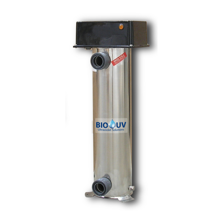
BIO UV O'CLEAR ELITE Manual

O CLEAR-Elite_(Anglais) - DOC016536 - Ind. A01 - 22/03/2021
INSTALLATION AND MAINTENANCE MANUAL
STERILIZER O’CLEAR ELITE

O CLEAR-Elite_(Anglais) - DOC016536 - Ind. A01 - 22/03/2021
Copyright BIO-UV
Marque, Modèles et Brevets déposés - Produits exclusifs
Page 2
We thank you for choosing a BIO-UV reactor.
Our equipment has been designed to give you reliable and safe operation for many years to come.
The BIO-UV reactors have been designed for speed and ease of installation.
Their design also makes them easy to maintain.
Read these instructions carefully in order to optimize the operation of your reactor.
TABLE OF CONTENTS :
pages
A. Safety Warnings.....................................................................................................................................................4
B. Symbols description..............................................................................................................................................5
C. Packing list .............................................................................................................................................................6
D. Technical characteristics ......................................................................................................................................7
E. Reminders and tips................................................................................................................................................8
E.1. Pool water condition..........................................................................................................................................8
E.2. Filtration ............................................................................................................................................................8
E.3. A filter must be maintained ...............................................................................................................................8
E.4. The filtration time must be respected................................................................................................................8
E.5. Floculation.........................................................................................................................................................8
E.6. Balanced water parameters..............................................................................................................................9
E.7. The various matter in water ..............................................................................................................................9
F. Installation guide..................................................................................................................................................10
F.1. Foreword .........................................................................................................................................................10
F.2. Usage environment.........................................................................................................................................11
F.3. Pre-assembly ..................................................................................................................................................11
F.3.1. Foot mounting..........................................................................................................................................11
F.3.2. Fittings assembly.....................................................................................................................................11
F.4. O’Clear reactor installation..............................................................................................................................12
F.5. Standard Installation .......................................................................................................................................13
F.6. Mounting the O’Clear Elite electrical cabinet onto a wall................................................................................14
F.7. Installation of temperature sensor/ saddle assembly......................................................................................15
F.8. Installation of the pH probe/probe holder/saddle assembly............................................................................15
F.9. Installing the pH injection heat contactor .........................................................................................................17
F.10. Instructions for electrical connections...........................................................................................................18
F.10.1. Electrical connections on the electrical cabinet O Clear .......................................................................18
F.10.2. Wiring to the filtration unit ......................................................................................................................19
F.10.3. Connection of the electrolysis cell .........................................................................................................20
F.10.4. Installation of the lamp cable in the reactor...........................................................................................21
G. Use of the O’Clear Elite cabinet..........................................................................................................................22
G.1. Description......................................................................................................................................................22
G.1.1. Overview .................................................................................................................................................22
G.1.2. Keypad....................................................................................................................................................22
G.1.3. LEDs........................................................................................................................................................23
G.1.4. Setting the production setpoint................................................................................................................23
G.2. Screen menus navigation...............................................................................................................................24
G.3. Electrolysis Menus..........................................................................................................................................25
G.3.1. Boost Mode.............................................................................................................................................25
G.3.2. Selecting the electrolysis operating mode ..............................................................................................25
G.3.3. Setting the inversion frequency of the current supplying the cell............................................................26
G.3.4. Electrolysis test .......................................................................................................................................26
G.4. pH Regulation Menu.......................................................................................................................................27
G.4.1. Manual injection ......................................................................................................................................27
G.4.2. Activation/deactivation of pH regulation..................................................................................................27
G.4.3. Calibration of the pH measurement ........................................................................................................27
G.4.4. Calibrating the pH probe .........................................................................................................................27
G.4.5. Setting the pH setpoint............................................................................................................................28
G.4.6. Specification of the pH corrector type.....................................................................................................28
G.4.7. Specification of the concentration of the pH corrector............................................................................28

O CLEAR-Elite_(Anglais) - DOC016536 - Ind. A01 - 22/03/2021
Copyright BIO-UV
Marque, Modèles et Brevets déposés - Produits exclusifs
Page 3
G.5. Parameters Menu...........................................................................................................................................29
G.5.1. Setting the date and time ........................................................................................................................29
G.5.2. Selecting the display language ...............................................................................................................29
G.5.3. Specification of the volume of the pool ...................................................................................................29
G.5.4. Sensors settings......................................................................................................................................29
G.5.5. Alarms settings........................................................................................................................................30
G.5.6. Calibration of the water temperature measurement ...............................................................................30
G.5.7. Settings reset ..........................................................................................................................................30
G.5.8. Code Parameter......................................................................................................................................30
G.5.9. Display parameters .................................................................................................................................31
G.6. Communication Menu.....................................................................................................................................31
G.6.1. Bluetooth Communication.......................................................................................................................31
G.7. Auxiliary Menu................................................................................................................................................32
G.7.1. “UV rate” Parameter (Aux. Rate).............................................................................................................32
G.7.2. « Electrolysis rate » Parameter (Elec. Rate)...........................................................................................32
G.7.3. Delay Parameter .....................................................................................................................................32
G.7.4. « Maintenance » Parameter....................................................................................................................33
G.8. Information Menu............................................................................................................................................33
G.9. Safety..............................................................................................................................................................34
G.9.1. Wintering mode.......................................................................................................................................34
G.9.2. Alarms.....................................................................................................................................................34
G.9.3. Important precautions regarding the peristaltic pump.............................................................................35
H. Pool preparation...................................................................................................................................................36
H.1. For a new pool or new water ..........................................................................................................................36
H.2. For old water...................................................................................................................................................36
H.3. In any case and regularly................................................................................................................................36
I. Checks before commissioning.............................................................................................................................37
J. Starting up.............................................................................................................................................................38
K. Four essential steps ............................................................................................................................................39
K.1. Water balance.................................................................................................................................................39
K.2. Filtration ..........................................................................................................................................................39
K.3. Check the salt rate..........................................................................................................................................39
K.4. Anti-algae treatment: maintain a minimum rate of free chlorine at 0.5 ppm...................................................39
L. Maintenance..........................................................................................................................................................40
L.1. Lamp replacement procedure .........................................................................................................................40
L.2. Quartz sleeve dismounting..............................................................................................................................42
L.3. Maintenance of the electrolytic cell .................................................................................................................44
L.4. Shutdown for extended periods / for winter.....................................................................................................45
L.4.1. Procedure.................................................................................................................................................45
L.4.2. Notes to be taken into account ................................................................................................................45
L.5. Maintenance of the pH regulation ...................................................................................................................46
L.5.1. pH probe ..................................................................................................................................................46
L.5.2. pH injection circuit....................................................................................................................................46
M. UV reacgtor Blown up view and spare parts ....................................................................................................47
N. Recycling ..............................................................................................................................................................48
N.1. Lamps and electronic components.................................................................................................................48
N.2. Mercury recovery............................................................................................................................................48
O. Warranties.............................................................................................................................................................49

O CLEAR-Elite_(Anglais) - DOC016536 - Ind. A01 - 22/03/2021
Copyright BIO-UV
Marque, Modèles et Brevets déposés - Produits exclusifs
Page 4
A. SAFETY WARNINGS
•Switch off the device 30 minutes before any intervention to let the
lamp cool down.
•The system must not operate without water flow (pumps
interlock)
Warning:
This device
includes an
UV-C emitter
RISKS OF
UV-C
RADIATION
•Never expose yourself to the radiation of the ultraviolet lamp
when lit. Never directly look at the light source. This may cause
severe injuries or burns and may even lead to loss of eyesight.
•When the lamp is running, do not take the lamp out of the
reactor or remove the protection covers.
•Do not operate the UV-C emitter when it has been removed from
the device housing.
•An unintended use of the device or a damage to its enclosure may
lead to leakage of hazardous UV-C radiation. UV-C radiation, even
in small doses, can be harmful to eyes and skin.
•When dismounting UV lamp or quartz tube, it is necessary to wear
protection gloves not to let fingerprints that could affect the UV
emissions quality
•The reactor must be disconnected from the electrical network for
maintenance purpose by qualified personal.
•Generally, any work on electrical parts must be carried out by
qualified and authorized personal.
•Even when stopped, power is present in the electrical unit so
make sure that the main power supply upstream of the electrical
cabinet isswitched off before carrying outany work on the equipment.
•Do not use the reactor if the power supply wire is worn or
damaged. In this case, it should be replaced by BIO-UV, its support
service or personal with a similar skill to avoid any hazard.
•To avoid electric short-circuits, do not place the electric wires or
the reactor in the pool water or in any other maintenance or
cleaning fluid.
•Do not perform electrical measurement on ballast output (risk of
overvoltage)
•Disconnect the O’Clear sterilizer before all maintenance and cleaning
operations.

O CLEAR-Elite_(Anglais) - DOC016536 - Ind. A01 - 22/03/2021
Copyright BIO-UV
Marque, Modèles et Brevets déposés - Produits exclusifs
Page 5
•Never dismount the quartz tube sealing washer when the
reactor is on load as the quartz tube could be blown out of the
reactor with force and injure you.
•In case of a microleakage, the reactor must be isolated and
drained to perform a maintenance as soon as possible.
•Do not use the O’Clear reactor for any other use than that for
which it was designed.
•The devices obviously damaged must not be operated.
•When replacing the lamps and/or during the annual cleaning of
quartz sleeves, check that the electrical part is in place and
correctly secured before switching on the sterilizer. Check that the
nut, washer and O-ring are correctly positioned, otherwise the
quartz sleeves could be expelled from their holder at speed and
injure you.
•This device can be used by children aged at least 8 years old and
by persons with physical, sensory or mental capabilities reduced
or lack of experience and knowledge, if they are properly
monitored or have been given instructions on the use of the
appliance safely and whether the risks have been apprehended.
•Children should not play with the appliance. Cleaning and
maintenance by the user should not be carried out by children
without supervision.
•The safety instructions can be requested by e-mail at the address
[email protected]. This manual can also be downloaded with the
link here below:
https://biouvgroup.sharepoint.com/:f:/s/Documentation
/EirOVTEdTvZFjnw3ImYLAw0Bqo0RetTwia5AzfI9WS
onWA?e=jYzSVk or the QR code on the right
B. SYMBOLS DESCRIPTION
General warning
symbol
Warning: UV radiation
Comment
Warning: electricity
Protective gloves must
be worn
Ready for operation
Warning Hot
surface
Ground wire required
Refer to installation and
maintenance manual

O CLEAR-Elite_(Anglais) - DOC016536 - Ind. A01 - 22/03/2021
Copyright BIO-UV
Marque, Modèles et Brevets déposés - Produits exclusifs
Page 6
C. PACKING LIST
.
UV reactor
Solvent weld fitting Ø75
Electrical cabinet
Electronics unit mounting
kit (wall mount, screws
and wall plugs)
REF: RAC015112
2 x Restrictors 75x63
Power cable
for electronics unit
Power cable
for electrolytic cell
Saddle
(in kit) x3
(2x1/2’’+1x3/4’’)
REF : RAC015404
2 x Restrictors 75x50
REF : RAC015404
Temperature sensor
x1
Amber pH probe
x1
Semi-flexible tubing
x1
Filter with ballast
x1
REF : PDP006036
REF : PDP000051
REF : PDP006041
REF : PDP006040
Injection connector
x1
Probe holder
x1
Stopper
x1
Calibration solutions
1x pH 7
REF : PDP016381
REF : PDP006039
REF : PDP006038
1 x pH 10
REF : PDP016382
Not included: the salt required to start the pool.
High purity salt must be used, in accordance with standard EN16401, A quality (without pouring agent and without
anti-caking agent)

O CLEAR-Elite_(Anglais) - DOC016536 - Ind. A01 - 22/03/2021
Copyright BIO-UV
Marque, Modèles et Brevets déposés - Produits exclusifs
Page 7
D. TECHNICAL CHARACTERISTICS
UNIT
O CLEAR 15 ELITE
O CLEAR 25 ELITE
REACTOR
Material
-
PVC
PVC
Maximum operating pressure
bar
3
3
MPa
0,3
0,3
Maximum flow rate (after head losses)
m3/h
15
25
A) Full length
mm
845
1091
B) Depth
mm
371
371
C) Fixation spacing
mm
624
870
D) Service spacing
mm
600
850
E) Width
mm
311
311
F) Low connection / Floor
mm
113
113
Weight
kg
12
14
Connection type
-
Solvent weld fitting
Solvent weld fitting
Inlet/outlet diameter with provided union fittings
mm
75
75
ELECTRICAL CABINET
Type
-
Independent cabinet
Independent cabinet
Material
PC
PC
Height
mm
363
363
Width
mm
266
266
Depth
mm
167
167
Cable length between cabinet/reactor
m
3
3
Weight
kg
3,3
3,3
Power supply
V
220-240
220-240
Frequency
Hz
50/60
50/60
Power cable type
mm²
3G0,75
3G0,75
Current rating
A
1,86-1,71
2,02-1,85
Absorbed power
W
385
417
Protection
-
Fuse (4A)
Fuse (4A)
Protection index
-
IP54
IP54
UV LAMPS
Number of lamps
-
1
1
Electrical power per lamp
W
55
87
Lamp type
-
High Output
High Output
UV power per lamp
W
17,5
28
Total UV power
W
17,5
28
Average life expectancy for 1 start/stop per day
h
13000
13000

O CLEAR-Elite_(Anglais) - DOC016536 - Ind. A01 - 22/03/2021
Copyright BIO-UV
Marque, Modèles et Brevets déposés - Produits exclusifs
Page 8
E. REMINDERS AND TIPS
Given the environment and operation of a swimming pool, it is essential to remember the core rules of the different
parameters - water conditions, filtration and water balance - that help to achieve, regardless of the water treatment
used, a result in line with our expectations while reducing the contribution of different chemicals and avoiding
unpleasant and costly accidents.
Prevention = pleasure and economy
E.1. Pool water condition
Water must circulate completely in the entire pool. The number of jets, skimmers (or overflows) ensures this
circulation and minimises any "dead zones".
The pump power obviously should match the volume of water to be able to treat it completely in a reasonable time
(3 to 4 hours).
The piping section should also match the pool volume.
Poor water conditions = growth of bacteria and algae.
E.2. Filtration
Filtration is fundamental to water treatment.
Its role is to retain suspended solids and different particles in the filter mass.
Good filtration saves on disinfectant products.
E.3. A filter must be maintained
The filter must be cleaned and descaled yearly with a special product (e.g. BIO-UV FILTER CLEAN) that eliminates
limestone deposits and clogging material.
Perform a backwash weekly.
E.4. The filtration time must be respected
Basic rule: half of the water temperature.
If over 28 °: filter permanently.
Obviously, the capacity and size of the filter must match the pump flow, or it can even be oversized.
E.5. Floculation
For sand filtration, adding a clarifying agent or flocculant is required to increase the filtration efficiency.
CAUTION: Never flocculate when using a diatom filter

O CLEAR-Elite_(Anglais) - DOC016536 - Ind. A01 - 22/03/2021
Copyright BIO-UV
Marque, Modèles et Brevets déposés - Produits exclusifs
Page 9
E.6. Balanced water parameters
•The pH indicates the alkalinity or acidity of the water. Maintaining pH 7 (neutral pH) is generally desirable.
❖If the pH is less than 7: acidic water, aggressive to the skin and the pool liners.
❖If the pH is greater than 7.4: possible discomfort for swimmers (itchy eyes), growth of algae,
increased limestone deposits, inefficiency of flocculants...
•The TH indicates the water hardness and its calcium and magnesium content.
For a value over 20 °F, adding a limescale sequestrant is recommended once during the season (e.g. BIO-
UV ANTI-LIMESTONE).
Very hard water causes limescale and damages the piping.
Very soft water (acid) can be corrosive.
•The TAC indicates the water bicarbonate and carbonate content, i.e. its alkalinity. Its level must be 10 to 15
°F and it can be modified by using suitable products (TAC plus).
E.7. The various matter in water
•Algae: these plants can grow in pools and are transported by air in large quantities. To treat them,
disinfectant alone would be used primarily at the expense of its bactericidal action. Therefore, it is
recommended to use an algaecide or special algaecide in conjunction with REMANENTS.
•Organic matter: conveyed by bathers, nature and the environment and non-toxic, they must be retained
by filtration and the various treatment processes.
•Micro-organisms: bacteria, viruses and fungi are brought by the same vectors and can be harmful to
health. The role of the O’Clear sterilizer is to destroy them. Adding REMANENT ensures their persistence
in the pool and prevents their development between two passages through the O’Clear sterilizer.
•Metal ions: iron, copper, manganese, etc. can be found in large quantities in well water or after treatment
of cultures (sulfation). These ions can also damage the liner and discolour the water
We recommend avoiding using well water to fill swimming pools.
However, it is possible to sequester these ions with specific products.
•Phosphates and nitrates: they are present in highly variable quantities and promote the growth of algae.
They can reveal groundwater pollution.
Avoid well water.

O CLEAR-Elite_(Anglais) - DOC016536 - Ind. A01 - 22/03/2021
Copyright BIO-UV
Marque, Modèles et Brevets déposés - Produits exclusifs
Page 10
F. INSTALLATION GUIDE
F.1. Foreword
BIO-UV reactors are ready to install, no works is required inside the reactor.
•The treatment capacity of the equipment must be appropriate for the volume of the pool to be treated,
the number of people using the pool, the presence of nearby equipment (overflow, reflecting pool,
slide, etc.) and the weather conditions where the equipment is installed.
•Use water from the mains water supply. Avoid water from natural sources (rain, run-off, lakes or
wells).
•Avoid any anti-algae including copper or other metals.
•Only use pH correction products recommended by your professional dealer. Do not use hydrochloric
acid or any other chemical product, as this may cause irreversible damage to the equipment.
•Check that the filtration pump and filter are in good condition and working correctly. Also check the
flow rate of the filtration pump, the capacity of the filter, and the outer diameter of pipework (either
50 or 63 mm).
•The equipment must be installed in a closed, dry and sufficiently ventilated room which is protected
from water sprays and UV rays. The temperature inside this room must not exceed 40°C.
→If these premises are located in a country with a hot and humid climate, they must be air
conditioned.
→If these premises are located in a country with a temperate climate, they must be equipped
with forced ventilation.
•Determine where exactly each component will be positioned, taking into account its size and the
length of its power cables. Also anticipate extra space around the equipment, in order to facilitate
access for maintenance.
•The pH corrector container must be installed a safe distance away from any electrical device or any
other chemicals. Failure to follow these instructions may lead to abnormal oxidation of the metal
parts, possibly resulting in complete device failure.
•Be very careful to ensure that the various components are correctly positioned in relation to each
other, as indicated in the installation diagram.
Saddles or the accessories holder must be positioned after any other treatment, cleaning or
heating device (just before flow out into the pool). They must be installed on the level (not inclined),
so that the pH probe and the injection connector are vertical.
If constraints related to the filtration circuit call for a different installation from that described in the
installation diagram, have this installation validated by a professional.
•The water pressure in the saddles or the accessories holder (depending on the equipment) must not
exceed 3 bar. All hydraulic components installed must be able to tolerate water pressures likely to
be encountered as part of normal use. There should be no leakage from any part, including pipework.

O CLEAR-Elite_(Anglais) - DOC016536 - Ind. A01 - 22/03/2021
Copyright BIO-UV
Marque, Modèles et Brevets déposés - Produits exclusifs
Page 11
F.2. Usage environment
Location
Room protected from direct sunlight and bad weather
Max altitude
From 0 to < 2000m
Degree of pollution
2
Overvoltage category
II
Protection class against electric shocks
I
Ambient temperature
between 5°C et 40°C
Corrosive environment
Protect the electrical box from any corrosive emanations
(hydrochloric acid vapors, salt…)
Install the O’Clear equipment in the equipment room, respecting the 0.1 and 2 safety areas around the volume
in accordance with the current installation rules (NF C15100).
F.3. Pre-assembly
F.3.1. Foot mounting
➢Fit the foot on the lower part of the reactor.
➢Using an Allen key size 5, mount the 4 screws as shown in the figure
opposite.
F.3.2. Fittings assembly
➢Using PVC glue, mount the fittings provided with the device on the inlet
and outlet of the reactor
➢If necessary, mount and glue the reductions corresponding to the piping
diameter on each fitting.
Under no circumstances should the reactor body be dismantled. The nuts at the four corners of the
reactor should never be loosened as the reactor could start to leak. Any intervention on these nuts
could void the warranty.

O CLEAR-Elite_(Anglais) - DOC016536 - Ind. A01 - 22/03/2021
Copyright BIO-UV
Marque, Modèles et Brevets déposés - Produits exclusifs
Page 12
F.4. O’Clear reactor installation
➢For an easier maintenance, we recommend to install a By-pass.
➢The reactor must be installed in vertical position (water inlet downward)
➢The reactor must be always located on the discharges after the filter.
➢It is necessary to provide a cleared space above the reactor of at least 850mm for O’CLEAR 25 or
600mm for O’CLEAR 15 to be able to bring the lamp and the quartz out and another space of at least
250mm behind the reactor to remove the electrode.
➢Flow direction must be observed
➢The maximum pressure of the piping should never be higher than the reactor maximum pressure (see Technical
characteristics table, page 4)
If there is a risk of overpressure, it is recommended to install an automatic drain or a relief valve
so that the pipe pressure remains lower than the reactor pressure.
➢If a bypass is used for the heating, the O’Clear equipment should be installed before the bypass
➢Using clamping collars (50, 63 or 75 mm diameter) secure the pH liquid injectors and pH probe in the correct
order.
➢The reactor is designed to be placed on the ground.
Upstream
valve
Downstream
valve
By-pass valve
Union Ø75
250mm

O CLEAR-Elite_(Anglais) - DOC016536 - Ind. A01 - 22/03/2021
Copyright BIO-UV
Marque, Modèles et Brevets déposés - Produits exclusifs
Page 13
F.5. Standard Installation
Principle diagram, the proportions are not respected
NB: There is no contraindication for the installation of the O’Clear reactor before or after the heater.
➢In some cases, installing a Pool Earth kit may be recommended :
Heater
Filter
Pump
UV Reactor
Pool
pH Injection
pH probe
Discharges
Skimmers
Temperature sensor
pH corrector container

O CLEAR-Elite_(Anglais) - DOC016536 - Ind. A01 - 22/03/2021
Copyright BIO-UV
Marque, Modèles et Brevets déposés - Produits exclusifs
Page 14
F.6. Mounting the O’Clear Elite electrical cabinet onto a wall
1. Attach the wall mount to the wall using the screws, washers and wall plugs provided, according to the
diagrams below.
2. Hang the electrical cabinet onto the wall mount.
REAR VIEW OF THE CABINET
FIXING HOOK

O CLEAR-Elite_(Anglais) - DOC016536 - Ind. A01 - 22/03/2021
Copyright BIO-UV
Marque, Modèles et Brevets déposés - Produits exclusifs
Page 15
F.7. Installation of temperature sensor/ saddle assembly
1) Mount the saddle 2on the pipe, as shown in the image opposite.
Note : use the 3/4’’ saddle, not the 1/2’’ one
2) Drill the top of the pipe through the hole of the saddle (see arrow
opposite), taking care not to damage the tapping.
3) Screw the temperature sensor 15 into the saddle 2, tightening
with hand. No sealing tape is required.
F.8. Installation of the pH probe/probe holder/saddle assembly
The life of the pH probe depends primarily on the strict observance of all the instructions provided
in this manual.
2
15
2
15
3
7
2
3
2
7
2
2
15

O CLEAR-Elite_(Anglais) - DOC016536 - Ind. A01 - 22/03/2021
Copyright BIO-UV
Marque, Modèles et Brevets déposés - Produits exclusifs
Page 16
1) Mount the saddle 2on the pipe, as shown in the image opposite.
2) Drill the top of the pipe through the hole of the saddle (see arrow
opposite), taking care not to damage the tapping.
3) Check that the probe bulb is properly immersed in the solution inside the storage vial.
If this is not the case:
a) Remove the storage vial from the probe (see photo below), and keep it for wintering.
b) Rinse the bulb with tap water.
c) Soak the probe for 30 minutes in tap water or in a suitable KCl solution (saturated potassium chloride).
d) Move directly to stage 5).
4) Remove the storage vial from the probe, and keep it for wintering.
Never touch the bulb of the probe.
5) Check that there are no air bubbles inside the bulb. If this is not the case, shake the probe by holding the bulb
downwards until the air bubble has risen into the body of the probe.
6) Following the image and the instructions shown opposite:
a) With the use of Teflon tape (not supplied), screw the probe
holder 7into the saddle 2.
b) Loosen nut Awithout removing it.
c) Insert the probe 3into the probe holder 7.
•Do not push the probe as far as the stop-point of the
pipe. Place the probe halfway up the pipe.
•The probe must be installed:
-after the filter and before any treatment device,
-on the top of the pipe,
-vertically, and on the level (not tilted).
d) Tighten nut A by hand.
2

O CLEAR-Elite_(Anglais) - DOC016536 - Ind. A01 - 22/03/2021
Copyright BIO-UV
Marque, Modèles et Brevets déposés - Produits exclusifs
Page 17
F.9. Installing the pH injection heat contactor
4
6
2
5
1) Mount the saddle 2on the pipe, as shown in the image..A..
Note : use the 1/2’’ saddle, not the 3/4’’ one
2)
Drill the top of the pipe through the hole of the saddle (see arrow
on the photo.A.), taking care not to damage the tapping.
3) Place the pH corrector container 12
as close as possible to the
equipment room’s internal ventilation and as far away as possible
from any electrical device.
4) Connect the filter with ballast 5to the peristaltic pump 14
, with
the semi-flexible tubing 4to be cut to the right size (see photos .B.
and .C.).
5) Insert the filter with ballast 5at the bottom of container 12.
6) With the use of Teflon tape (not supplied)
, screw the injection
connector 6into the saddle 2.
Following image .D..
(exploded view of the injection connector
6
), respect the direction of assembly of the parts, and in
particular the direction of the arrow engraved on the
connector.
Failure to follow these instructions can lead to the
peristaltic pump being damaged.
7) Connect the injection connector 6to the peristaltic pump 14
, with
the semi-flexible tubing, 4to be cut as needed.
A
B
C
D
14
1
4
6
12
5
2
4

O CLEAR-Elite_(Anglais) - DOC016536 - Ind. A01 - 22/03/2021
Copyright BIO-UV
Marque, Modèles et Brevets déposés - Produits exclusifs
Page 18
F.10. Instructions for electrical connections
IMPORTANT :
•Connections must be made by a qualified technician.
•A residual current device (RCD) not exceeding 30mA must be present and a fuse
or a thermal breaker should be installed on the device power supply.
•The supply voltage must be the same as that described on the label affixed to the side
of the unit.
•The O’Clear ultraviolet equipment must be used for filtration and thus operate with this
device => the power cable must be wired to the contactor coil of the pump (timer) in
220-240V (Caution to 380V!) the main electrical cabinet (See wiring diagrams below)
•Before making connections, turn off the power supply.
•A disconnection means must be provided on the power supply of the device to allow a
complete power cut according to the installation rules. This should be marked in order
to be quickly identified
•A disconnection means shall be provided in the fixed piping according to the installation
rules
The O’Clear device has been wired for a connection to the ground !
F.10.1. Electrical connections on the electrical cabinet O Clear
Cabinet connections :
T° : Connection for temperature sensor
Flow : Connection for flow swich
or empty container sensor.
com : Modbus connection (not used)
Ext : Connection for a flap position switch,
or an external control,
pH: Connection of the pH probe
❶

O CLEAR-Elite_(Anglais) - DOC016536 - Ind. A01 - 22/03/2021
Copyright BIO-UV
Marque, Modèles et Brevets déposés - Produits exclusifs
Page 19
Cell : Connection for the electrolytic cell using the corresponding power cable.
Lamp : UV lamp cable gland.
AC : Power cable connection for electronics unit (220 V - 50/60 Hz).
Permanently connect the electronics unit to the electrical unit, by linking it to the filtration pump
contactor.
(Reminder : A sufficient flow of water must be maintained in the electrolytic cell when connected to a
power supply).
Note : The drawer ❶contains a fuse ❷contains a fuse
❷
(6.3 A time-delay fuse - 5x20 mm), as well as a
compartment to store a spare fuse ❸(not supplied):
F.10.2. Wiring to the filtration unit
a) General case
A contactor with a coil supplied with 220-240 V AC:
1. Connect the O Clear electrical cabinet to the filter box as shown below :
Earth= Green/Yellow,
L = Live = Brown (220-240Vac),
N = Neutral = Blue
2. Connect the O Clear electrical cabinet to the coil of the contactor (A1/A2)
3. Make sure that the fuse or circuit breaker is suited to the power of all connected devices
Never connect the O Clear electrical cabinet to the same terminal block as the
filtration pumps and / or suppressors of your installation.
❷
❸
❶
O Clear Elite
electrical cabinet
Contactor
Clock
Pump
Filtration unit

O CLEAR-Elite_(Anglais) - DOC016536 - Ind. A01 - 22/03/2021
Copyright BIO-UV
Marque, Modèles et Brevets déposés - Produits exclusifs
Page 20
b) Special case
A contactor with an unpowered coil:
1. Use a relay (not provided) to :
•- Obtain a voltage identical to that of the coil
•- Accept at least 5 amps on its contacts.
2. Connect the O Clear electrical cabinet with the relay as shown below :
Earth= Green/Yellow,
L = Live = Brown (220-240Vac),
N = Neutral = Blue
3. Connect the O Clear electrical cabinet to the relay output.
4. Make sure that the fuse or circuit breaker is suited to the power of all connected devices.
Never connect the O Clear electrical cabinet to the same terminal block as the
filtration pumps and / or suppressors of your installation
F.10.3. Connection of the electrolysis cell
All you have to do is plug the electrolysis cable connector coming out of the reactor into the corresponding socket:
"Cell" in the illustration in paragraph F.10.1 Electrical connections on the electrical cabinet O Clear, page 18.
The electrolysis cell is not polarized: the wires can be connected either to one or the other of the electrode
terminals.
O Clear Elite
electrical cabinet
Relay
Clock
Pump
Filtration unit
Contactor
Table of contents
Other BIO UV Laboratory Equipment manuals
