BIQU B1 User manual


Catalogue
1. Packing List.................................................................................................1
2. Equipment parameters.............................................................................. 2
3. Installation equipment...............................................................................3
4. Platform Calibration.................................................................................17
4-1 Platform Calibration...................................................................... 17
4-2 Fill in filament................................................................................ 21
5. Ready to print.......................................................................................... 22
5-1 Introduction to working mode......................................................22
5-2 Installing Driver software.............................................................. 23
5-3 Install Ultimaker Cura Software.................................................... 27
5-4 Software Settings...........................................................................30
5-5 Usage of Ultimaker Cura Software................................................36
6. Start Printing............................................................................................ 38
6-1 Offline printing.............................................................................. 38
6-2 Online Printing...............................................................................40
7. Other Functions....................................................................................... 42
7-1 Manual leveling............................................................................. 42
7-2 Automatic Leveling(Optional)..................................................45
7-3 Intelligent filament detection Sensor Module (Optional)............ 47
7-4 Model Preview...............................................................................49
7-5 Marlin Operating System...............................................................57
8. Troubleshooting.......................................................................................59
9. Cautions................................................................................................... 63
1
BIQU-B1 USER MANUAL
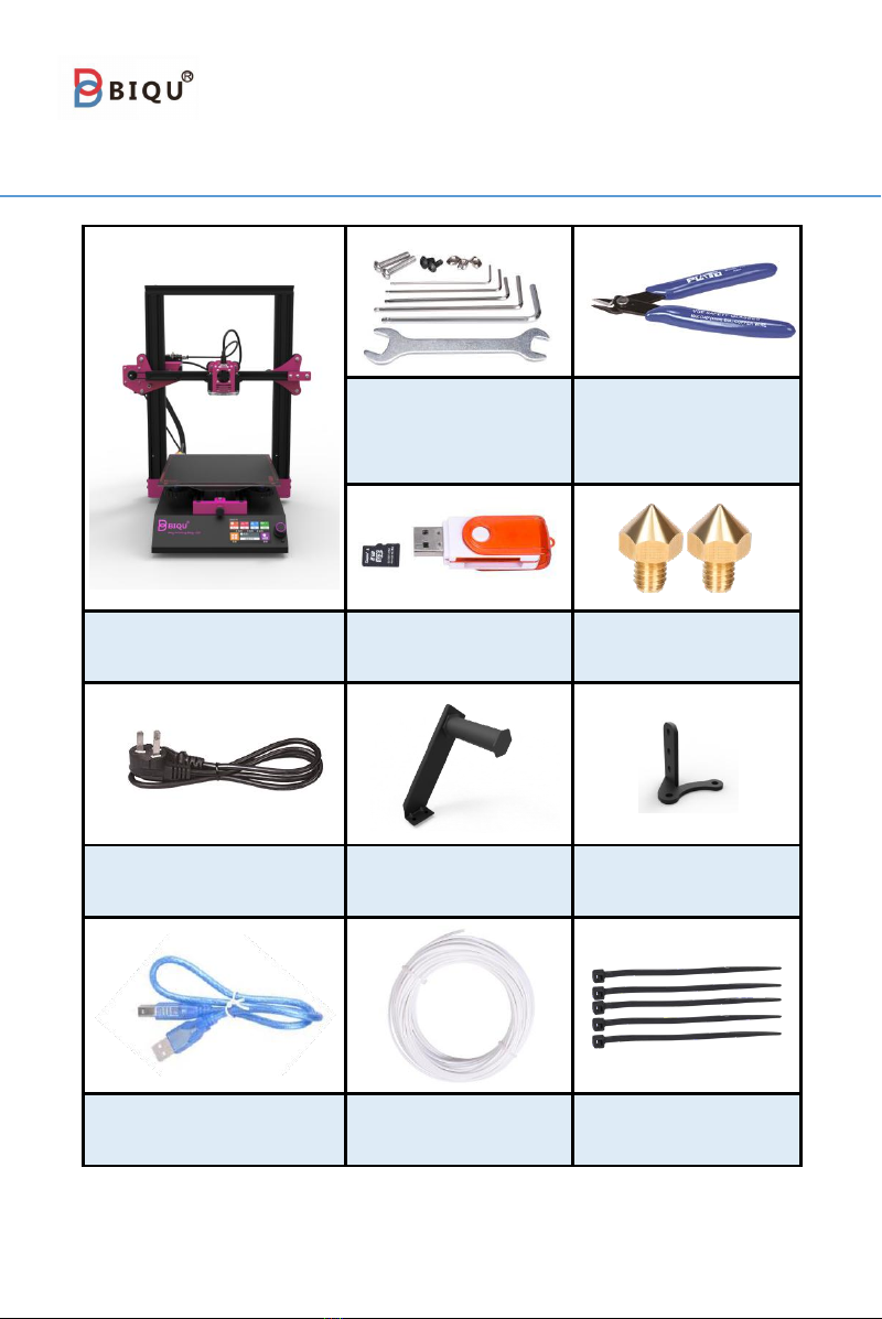
1. Packing List
Wrench and screw
bag
(1set)
Diagonal pliers
(1pcs)
BIQU-B1
(1pcs)
TF card and card
reader (1set)
Nozzle
(2pcs)
Power cable
(1pcs)
Rack
(1pcs)
BLtouch stand
(1pcs)
Data cable
(1pcs)
Filament for test
(45g)
Cable tie
(5pcs)

2
WWW.BIQU.EQUIPMENT
2. Equipment parameters
The basic parameters
Printer Name
BIQU-B1
Printing Size
235 x 235 x 270mm
Molding Tech
FDM
Nozzle Quantity
1 PCS
Layer Thickness
0.1mm - 0.3mm
Nozzle Diameter
Standard 0.4mm
Printing Accuracy
±0.05mm
Filament
PLA
Slicing Format
STL / OBJ/ AMF
Connecting Method
Via data cable / TF card / USB
Slicing Compatible
With Cura / Repetier-Host / Simplify 3D
Rated Voltage
100 - 120V / 200 - 240V 50 / 60 HZ
Output Voltage
24V
Rated Power
270W
Max Temp of Hot Bed
100℃
Max Temp of Nozzle
260℃
OS compatible
with Win 7 / Win 10
Maxium operating speed
180mm/s
Max Printing Speed
100mm/s
Normal Printing Speed
60mm/s
Language Transform
Supported
Resume Printing
With resume printing function
Filament Run Out Detection
With filament run out detection function

3
BIQU-B1 USER MANUAL
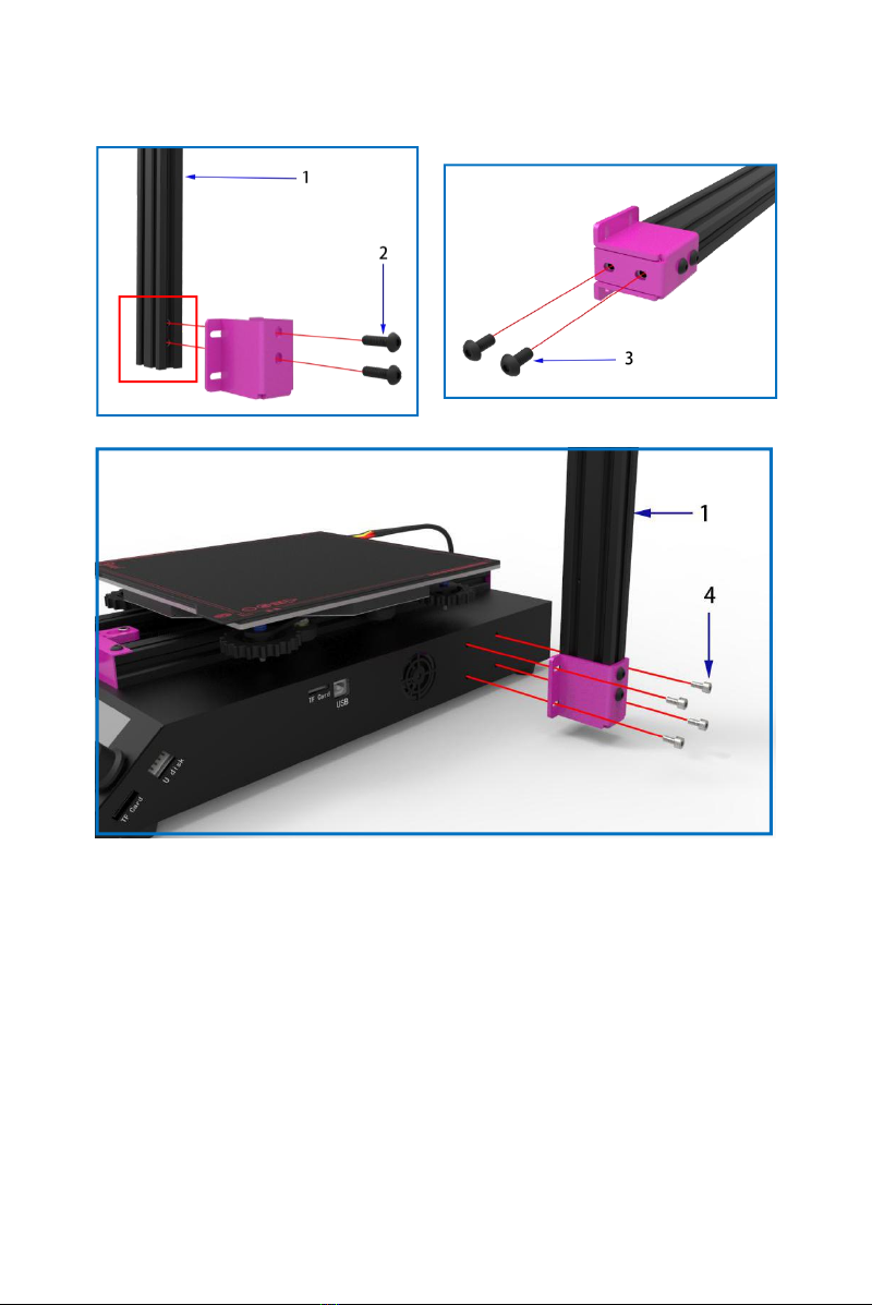
3. Installation equipment
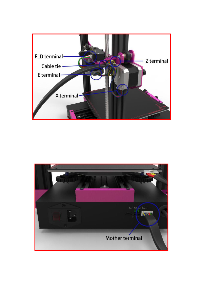
Step 1
Connecting the terminal wire to the socket of the hot bed.
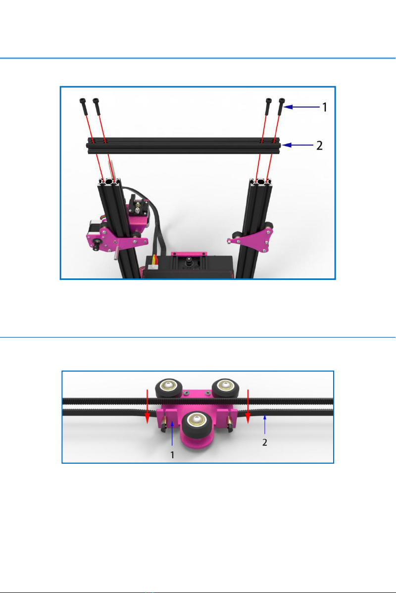
Step 2
There are two M5 threaded holes on the end of the 2040 aluminum
profile,which is used for mounting the M5×16 hex socket head screws.
4
WWW.BIQU.EQUIPMENT
1.2040 aluminum profile—length 456mm (1pcs)
2. M5×16 hexagon round-head screws (2pcs)
3. M5×10 hexagon round-head screws (2pcs)
4. M4×8 hexagon cup-head screws (4pcs)
5
BIQU-B1 USER MANUAL
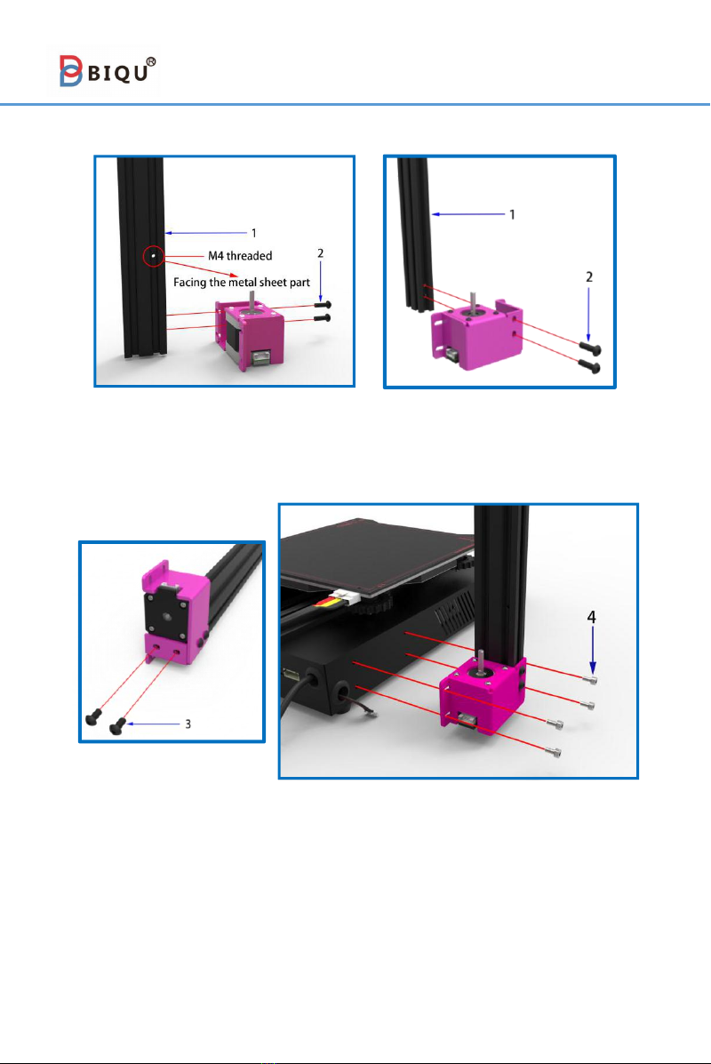
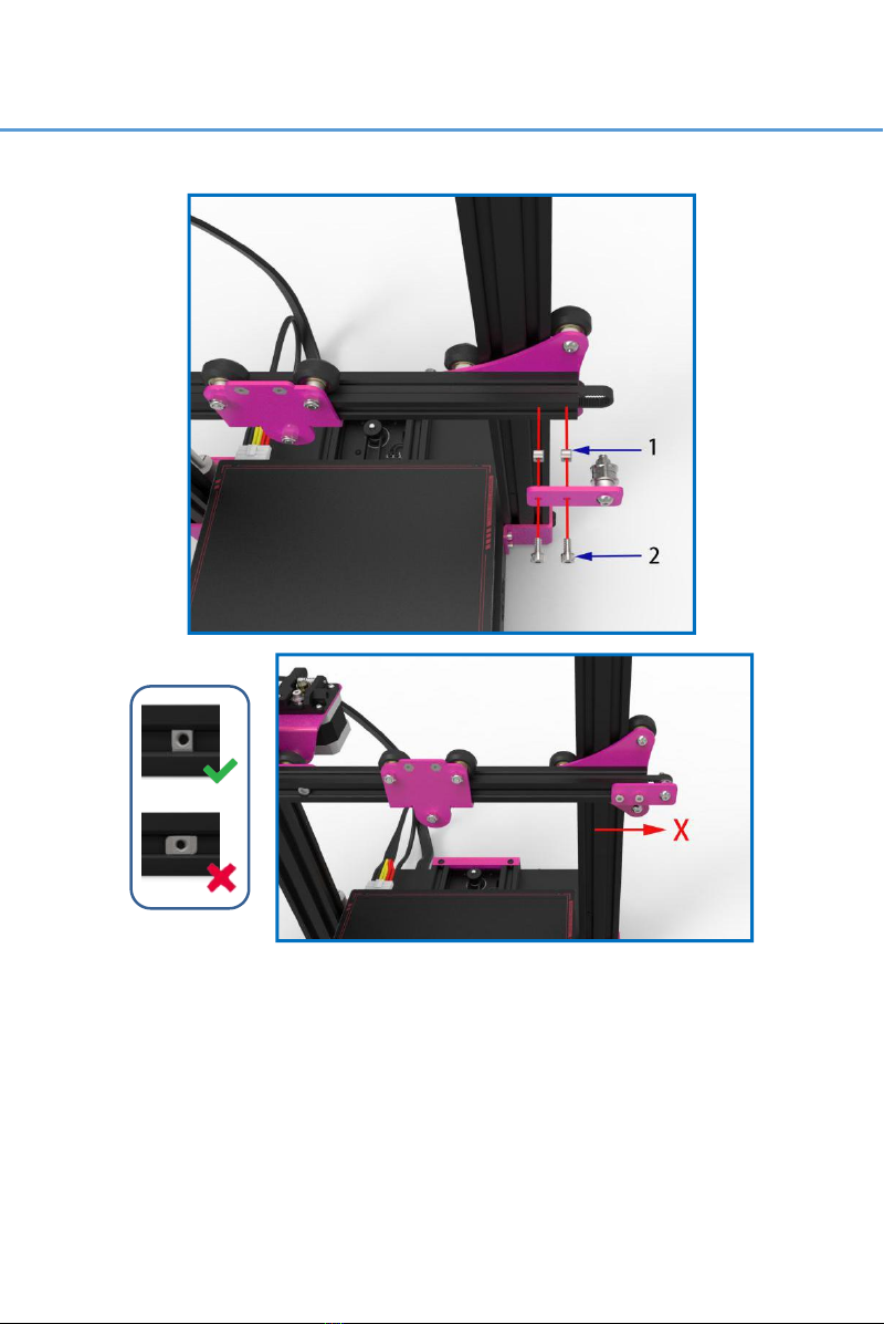
Step 3
There is a M4 threaded holes on another 2040 aluminum profile.
When installation, users make the threaded hole face the metal sheet
part.
1. 2040 aluminum profile--length 456mm (1pcs)
2. M5×16 hexagon round-head screws (2pcs)
3. M5×10 hexagon round-head screws (2pcs)
4. M4×8 hexagon cup-head screws (4pcs)

6
WWW.BIQU.EQUIPMENT
Step 4
1. T8 screw (1pcs)
2. Coupling device (1pcs)
There are machine screws inside the coupling device, which is used to
tighten the motor shaft and screw rod. The set screw is aligned with the plane
of the motor shaft when installing.
Step 5
1. M3×6 hexagon round-head screws (4pcs)
2. Hexagonal isolation column (1pcs)
7
BIQU-B1 USER MANUAL
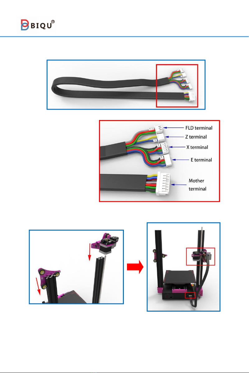
Step 6
4 in 1 terminal wire
8
WWW.BIQU.EQUIPMENT
As shown above, installing the 4 in 1 terminal wire to its
corresponding position. Then there are two key slots on the metal
sheet part. Users can use a cable tie to fix the terminal wire through
them.

9
BIQU-B1 USER MANUAL
1. Eccentric nut
Awareness: As the picture, please check whether the
interfaces are loose. If they are loose, please tight the eccentric nut
with wrench and make the groove of eccentric nut approach the
aluminum profile. Pulley on eccentric nut will preload aluminum
profile. The printer will be more stable by this way.
Step 7
Connecting the terminal wire on side to the motor’s port.
10
WWW.BIQU.EQUIPMENT
Step 8
、
1. M5×25 hexagon cup-head screws(4pcs)
2. 2020 aluminum profile—length 323mm(1pcs)
Step 9
1. X slider sheet(1pcs)
2. Belt(1pcs)

11
BIQU-B1 USER MANUAL
Step 10
1. M4×8 hexagon cup-head screws(2pcs)
2. M4 boat-shape nut(2pcs)
3. 2020 aluminum profile—length 338mm(1pcs)
4. M5×18 hexagon cup-head screws(2pcs)
The boat-shape nut may rotate during installation. Users could
use the screws to fix it on the aluminum profile.
Step 11
Installing the belt onto the 2020 aluminum profile.
12
WWW.BIQU.EQUIPMENT
Step 12
1. M4 boat-shape nut(2pcs)
2. M4×8 hexagon cup-head screws(2pcs)
Notice: The boat-shape nut may rotate during installation. Users
could use the screws to fix it on the aluminum profile.
When installation, in order to tighten the pulley and the belt,
users could push the parts slowly in the X direction.

13
BIQU-B1 USER MANUAL
Step 13
1. M3×8 hexagon cup-head screws(2pcs)
Step 14
1. Feed tube(1pcs)
2. Quick connector(2pcs)

14
WWW.BIQU.EQUIPMENT
Step 15
Step 16
1. M4×8 hexagon round-head screws(2pcs)
2. M4 boat-shape nut(2pcs)
The boat-shape nut may rotate during installation. Users could
use the screws to fix it on the aluminum profile.

15
BIQU-B1 USER MANUAL
Step 17
1. Type-C data cable(1pcs)2. Cable tie(1pcs)
As shown above, there are two key slots on the metal sheet part.
Users can use a cable tie to fix the Type-C cable through them. But
before fixing the data cable, users would better leave a certain length
at the Type-C cable's end which closes to the nozzle. It facilitates the
movement of the nozzle.
Awareness:
1.do not unplug the Type-C data cable when the machine is on.
2.The Type-C cable is customized, it can not be replaced by others.
16
WWW.BIQU.EQUIPMENT
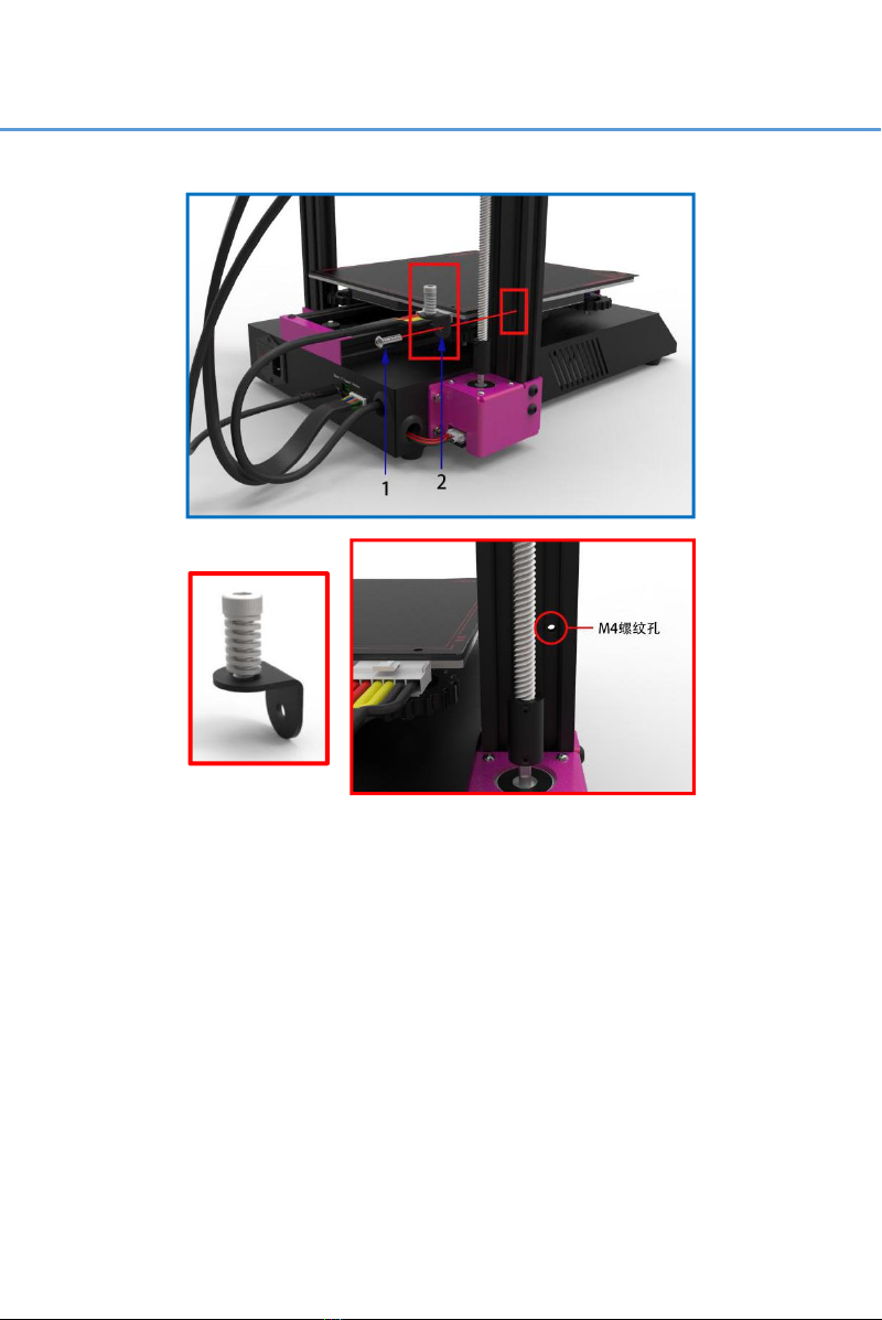
Step 18
1. M4×16 hexagon round-head screws(1pcs)
2. Z axis limit module
Fixing the Z-axis limit module on the aluminum profile by using the
M4 threaded holes and the above screws.
Awareness: Please check all the screws and make sure that they are
properly installed.
Installation Finished!
17
BIQU-B1 USER MANUAL
4. Platform Calibration
4-1 Platform Calibration
After the installation of BIQU B1, users need to perform a platform
calibration on BIQU B1. The steps are as follows:
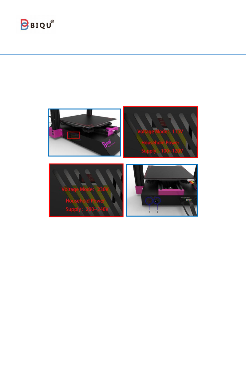
Step 1
1. Power switch
2. Power cord socket
Awareness: Before turning on, please check whether the
voltage mode matches your household power supply. If not, you
can select the mode by using screwdriver.
Confirming that the wiring is steady and correct. Inserting one
end of the power cord into the power cord socket and the other
end into the household power supply, and then turn on the power
switch of the machine.
Awareness: do not unplug the Type-C data cable when the
machine is on.
18
WWW.BIQU.EQUIPMENT
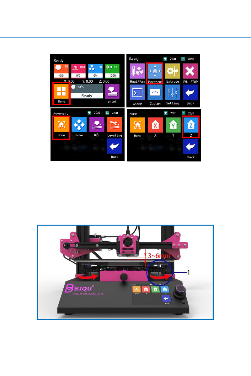
Step 2
Clicking on the touch screen homepage① “Menu ”→②
“Movement”→③“Home”→④“Z”。
The nozzle moves back to the zero point of the Z axis, which is
above the platform. Twist the 4 hand-tight nuts counterclockwise
under the hot bed so that there is a distance of 3 ~ 6mm between
the hot bed and the nozzle.
1. Hand-screw nut(4pcs)
①
②
④
③
Table of contents
Other BIQU 3D Printer manuals


Popular 3D Printer manuals by other brands


Monoprice
Monoprice 33820 user manual

Kulzer
Kulzer cara Print 4.0 Instructions for use

FLASHFORGE 3D PRINTER
FLASHFORGE 3D PRINTER CREATOR PRO 2 user guide

MiiCraft
MiiCraft MiiCraft+ user manual

NJIT Makerspace
NJIT Makerspace Trotec Speedy 400 Flexx quick start guide

SprintRay
SprintRay MoonRay quick start guide