4)
Plug the AC power adapter into any standard
electrical outlet. Or attach the optional battery clip
assembly to a 12V battery. The other end of the
cable should already be plugged into the power
jack located above Power on the back of the unit.
The AC adapter shall remain readily operable.
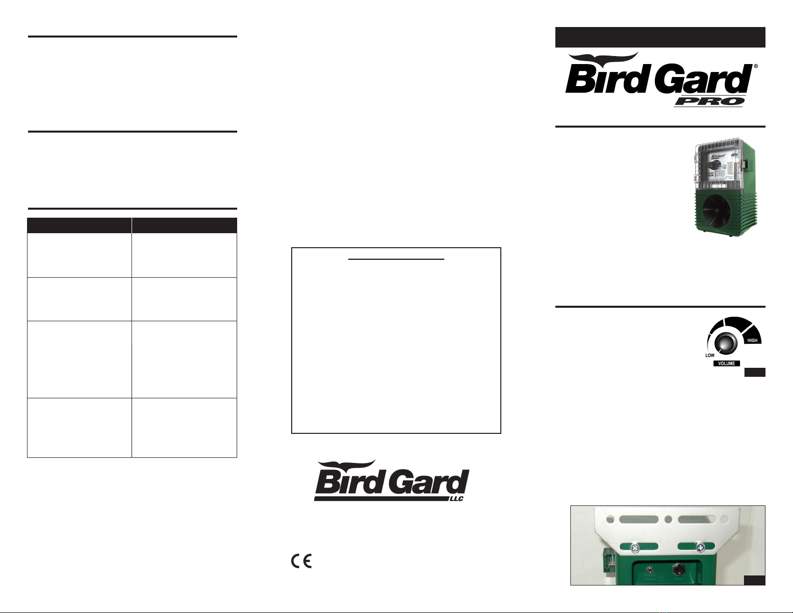
5)
Make sure the volume setting is set to LOW (all
the way counterclockwise).
6)
Slide the power switch to the right to the INT/EXT.
SPKR position. The unit may take a few seconds
before starting.
7)
Adjust the volume to the desired level.
8)
The Bird Gard
®
Pro allows the addition of an
optional extension speaker. An extension speak-
er may be operated as a “stand-alone” speaker
OR along with the internal speaker in the front
of the Bird Gard
®
Pro unit. Plug in the Extension
Speaker into the jack on the back of the unit.
Then move the slide switch on the front of
the control panel (upper right hand corner) to
INT/EXT. SPKR (to operate BOTH speakers)
OR to EXT. SPKR ONLY (to operate ONLY the
Extension Speaker).
PROGRAMMING YOUR BIRD GARD®PRO
To program your Bird Gard®Pro unit you will need a
small screwdriver, toothpick, or other pointed, rigid
object to toggle the switches in the switch array.
The switch array banks are located in the bottom
right hand corner on the front of the unit (to the right
of “RECORDINGS”) inside the front cover door. A
switch is ON if the switch is moved to the right-hand
side by sliding the switch to the right. The switch is
OFF when moved to the left-hand side.
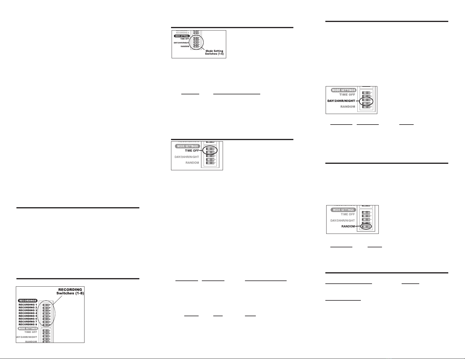
RECORDING SETTING SWITCHES
The RECORDINGS switches are the first eight
switches in the switch
array. Each switch
has a recording
number to the right
of it that corresponds
with the bird descrip-
tions listed on the foil
label affixed on the
front inside and below the front cover door.
MODE SETTING SWITCHES
The Mode Setting switch-
es set the various modes
of operation: such as the
amount of time between
playing bird distress or
predator/raptor calls, when the unit will operate
(day only, night only, or 24 hours), and whether
the unit will operate in the Random Mode or
Normal Mode.
Switch Mode or Function
1 Sets the Time-Off Period
2 Sets the Time-Off Period
3 Sets the Time the unit plays
4 Sets the Time the unit plays
5 Turns Random Mode On or Off
TIME OFF SWITCHES
The two Time-Off switches
are located just below the
Recording switches in the
switch array. When the unit
is set to one of the various
Time-Off modes, the unit will delay a number of
seconds or minutes between recorded sounds.
Please note that the unit will play all of the selected
recordings (either sequentially or non-sequentially,
depending on the Random Mode) then it will go
into a delay. The time the unit stays off depends
on the Time-Off and the Random Mode settings.
If the unit is operating in Random Mode, the unit
will delay anywhere from the minimum value to
the maximum value for that Time-Off setting. If
the unit is not in Random Mode, it will delay only
the minimum value. To set the Time-Off period
(or delay interval), use the following settings on
switches 1 and 2 in the mode function settings.
Switch 1 Switch 2 Time-Off Period
ON OFF Short
OFF ON Medium
ON ON Long
OFF OFF Extra Long
Mode Min Max
Short 17 sec 50 sec
Medium 1 min 4:15 min
Long 5:00 min 10:00 min
XLong 10 min 30 min
TIME OF OPERATION SWITCHES
The two “DAY/24HR/NIGHT” switches are located
just under the Time-Off switches in the bottom
switch array. ‘Night Mode’ operates the unit at
night and ‘Day Mode’ operates the unit during the
day. However, the photocell that senses the sun-
light is susceptible to bright lights. Take care not
to have bright lights shining towards the unit since
this can prevent the unit from operating properly.
In 24HR mode, the unit will operate continuously,
regardless of the time of day. To set the time period
for the unit to operate set
switches 3 and 4 in the
Mode Function settings to
the following:
Switch 3 Switch 4 Mode
ON OFF Day Only
OFF ON 24-Hour
ON ON Night Only
OFF OFF also Night Only
RANDOM OPERATION SWITCH
The “Random” switch is the bottom switch in
the switch array. In the Random Mode, the
unit randomly plays the selected recordings in
non-sequential order. When not operating in the
Random Mode, the unit plays the selected record-
ings sequentially. The Random Mode is recom-
mended to keep birds from
adapting to a preset pattern
of sounds. To operate the
unit in Random mode, set
switch 5 as follows:
Switch 5 Mode
ON Random mode ON
OFF Random mode OFF
PROGRAMMING EXAMPLE
Recording Switches: Results
1, 3, 5 and 6 to “ON” position Plays Bird 1, 3, 5 & 6
Mode Switches
1 = “OFF” position
2 = “ON” position (Medium), every 1 to 4 minutes
3 = “ON” position
4 = “OFF” position Operates during daylight hours only
5 = “ON” position In random, non-sequential order