Bishamon UNILIFT UNI-20 User manual

SERVICE
MANUAL
MANUAL
SERVICE
MANUAL
MANUAL
Model UNI-20
UNILIFT
PALLET TRANSPORTER & POSITIONER
TM
Patents Pending
For Serial Numbers 1110803 and Earlier

BISHAMON INDUSTRIES CORPORATION
5651 East Francis Street
Ontario, California 91761, USA
(909) 390-0055 (800) 231-3187
Date Placed in Service:
Serial Number:
Dealer:

Table of Contents
Contents Page
Getting Started ....................................................................................................................................................................................................1
Inspection............................................................................................................................................................................................................ 1
Operator Safety................................................................................................................................................................................................... 1
Operator Training ............................................................................................................................................................................................1
Safety Definitions ............................................................................................................................................................................................1
Dangers, Warning and Cautions ..................................................................................................................................................................... 1
Hazard Locations ............................................................................................................................................................................................3
Safety Warning Label Locations......................................................................................................................................................................4
Responsibility of Owners/Users ......................................................................................................................................................................5
Specifications ......................................................................................................................................................................................................5
Functional Description.........................................................................................................................................................................................6
Unpacking the UniLift ..........................................................................................................................................................................................6
Preperation for Use .............................................................................................................................................................................................7
Operating Instructions ........................................................................................................................................................................................ 11
General Instructions....................................................................................................................................................................................... 11
Brake Operation............................................................................................................................................................................................. 11
Pallet Jack Mode Operation...........................................................................................................................................................................12
Stacker Mode/Work Positioner Operation......................................................................................................................................................12
Stacker Mode/Positioning a Pallet..................................................................................................................................................................13
Stacker Mode/Pallet Obstruction....................................................................................................................................................................13
Routine Maintenance..........................................................................................................................................................................................14
Troubleshooting..................................................................................................................................................................................................22
List of Figures
Figure 1 - Hazard Locations.............................................................................................................................................................................3
Figure 2 - Safety Warning Label Locations.......................................................................................................................................................4
Figure 3 - Specification Drawing.......................................................................................................................................................................5
Figure 4 - Functional Description......................................................................................................................................................................6
Figure 5 - Forklift Lift Points..............................................................................................................................................................................7
Figure 6 - Installation Components...................................................................................................................................................................7
Figure 7 - Operator Console.............................................................................................................................................................................8
Figure 8 - Outriggers Fully Retracted LED Indicators.......................................................................................................................................8
Figure 9 - Right Outrigger Extending LED Indicators.......................................................................................................................................8
Figure 10 - Right Outrigger Extended LED Indicators........................................................................................................................................ 9
Figure 11 - Left Outrigger Extending LED Indicators..........................................................................................................................................9
Figure 12 - Outriggers Fully Extended LED Indicators....................................................................................................................................... 9
Figure 13 - Left Outrigger Retracting LED Indicators......................................................................................................................................... 9
Figure 14 - Right Outrigger Retracting LED Indicators.......................................................................................................................................9
Figure 15 - Right Outrigger Stopped Mid-Travel LED Indicators.......................................................................................................................10
Figure 16 - Left Outrigger Stopped Mid-Travel LED Indicators......................................................................................................................... 10
Figure 17 - Outrigger Obstruction LED Indicators............................................................................................................................................. 10
Figure 18 - GMA Pallet Dimensions ..................................................................................................................................................................11
Figure 19 - Brake Operation.............................................................................................................................................................................. 11
Figure 20 - Pallet Jack Mode............................................................................................................................................................................. 11
Figure 21 - Stacker Mode..................................................................................................................................................................................12
Figure 22 - Handle Assembly Removal.............................................................................................................................................................14
Figure 23 - Upper Console Cover Removal ......................................................................................................................................................15
Figure 24 - Lower Battery Cover Removal........................................................................................................................................................ 15
Figure 25 - Main Power Fuse............................................................................................................................................................................15
Figure 26 - Mast Cover Clamp ..........................................................................................................................................................................16
Figure 27 - Roller Installation.............................................................................................................................................................................16

Contents Page
Figure 28 - Linkage Lever Arms ........................................................................................................................................................................16
Figure 29 - Mast Inspection...............................................................................................................................................................................17
Figure 30 - Brake Lubrication Points.................................................................................................................................................................18
Figure 31 - Outrigger Inspection Points.............................................................................................................................................................18
Figure 32 - Outrigger Linkage............................................................................................................................................................................19
List of Charts
Chart 1 - Daily Inspection Items.....................................................................................................................................................................17
Chart 2 - Weekly Inspection Items.................................................................................................................................................................18
Chart 3 - Detailed Inspection and Maintenance.............................................................................................................................................20
Chart 4 - Recommended Hydraulic Fluids.....................................................................................................................................................20
Chart 5 - 2 Year/5000 Cycle Maintenance Items............................................................................................................................................21
Chart 6 - Troubleshooting...............................................................................................................................................................................22

1
GETTING STARTED
PLEASE READ THIS MANUAL CAREFULLY BEFORE USING THE UniLift™ Pallet Transporter and Positioner. The safety of all persons installing,
using or servicing the UniLift™ is of utmost importance to Bishamon. The UniLift™ is capable of lifting heavy loads and is capable of causing
SEVERE PERSONAL INJURY if used improperly or certain safety precautions are not taken. When properly used and maintained, the UniLift™
will provide many years of safe, trouble free service. If you have any questions about any of the instructions in this manual or about the use of this
product, PLEASE contact your DEALER or Bishamon Industries Corporation.
UniLift™ is a trademark of Bishamon Industries Corporation. Throughout this service manual the UniLift™ may be referred to as the “Unit”, the
“Lift” or the “Lifter”.
INSPECTION
IMMEDIATELY upon receipt of the palletized UniLift, visually inspect the unit for damage. Any damage to the unit MUST BE NOTED on the
DELIVERY RECEIPT and photographed, if possible. Next, remove all packing and strapping material and thoroughly inspect the UniLift for any
concealed damage that was not readily apparent during the preliminary inspection. Refer to the “Unpacking the UniLift” section of this manual
for instruction on how to remove the unit from the pallet. Any concealed damage found that was not noted on the delivery receipt should be
IMMEDIATELY reported in writing TO THE DELIVERING CARRIER.
OPERATOR SAFETY
OPERATOR TRAINING
Only trained and authorized personnel shall be permitted to operate a UniLift. User responsibilities, including “General Safety Practices” and
“Operating Safety Rules and Practices”, are defined in ANSI/ITDF B56.10-2006 “Safety Standard for Manually Propelled High Lift Industrial Trucks”.
It is the responsibility of the Owner/User to ensure compliance with this standard. Bishamon does not offer operator training. Operator training
programs may be offered by your local Bishamon dealer or available online.
SAFETY DEFINITIONS
Bishamon uses the following system to identify the degree of risk associated with hazards and unsafe practices.
DANGER - Immediate hazard which will result in SEVERE PERSONAL INJURY or DEATH.
WARNING - Hazard or unsafe practice which could result in SEVERE PERSONAL INJURY or DEATH and PROPERTY DAMAGE.
CAUTION - Hazard or unsafe practice which could result in MINOR PERSONAL INJURY and PROPERTY DAMAGE.
DANGER
1. READ THIS MANUAL COMPLETELY BEFORE USING THE UNILIFT. THOROUGHLY UNDERSTAND AND FOLLOW ALL SAFETY
INSTRUCTIONS. DO NOT operate the UniLift unless you have been trained and authorized to do so.All operators must understand and
be familiar with the operation and function of all controls and indicators.
2. Afalling load can cause SEVERE PERSONAL INJURY or DEATH. NEVER go under the loaded or unloaded forks. All maintenance
should be performed with the unloaded forks in the fully lowered position or securely blocked in a raised position.
3. Afalling load or tip-over can cause SEVERE PERSONAL INJURY or DEATH.
DO NOT travel with the load elevated. ALWAYS travel with the outriggers retracted and the forks in the lowest position possible.
ALWAYS ensure others are well clear of the UniLift when loads are raised or lowered.
DO NOT use the UniLift on a slope, unlevel or unstable surface.
4. NEVER sit or stand on the forks. NEVER allow others to sit, stand or ride on the forks. Sudden movement could cause loss of balance
resulting in SEVERE PERSONAL INJURY or DEATH.
5. Use extreme care when handling or working around batteries. Improper handling can cause SEVERE PERSONAL INJURY or DEATH.
ALWAYS use eye protection and protective clothing when handling batteries. Batteries contain acid which can cause severe burns and
injury.
NEVER expose a battery to extreme heat, open flames or sparks. Battery vapors are explosive.
6. The UniLift is a NFPA truck type E. DO NOT use the lift in an area where potentially explosive dusts, gases or vapors may be present.
Failure to comply may result in an explosion and cause SEVERE PERSONAL INJURY or DEATH.
WARNING
1. The UniLift is designed for use with stable, uniformly distributed, palletized loads on a solid, level and dry floor. DO NOT use the lifter for
any purpose other than its intended use. Improper use could result in SEVERE PERSONAL INJURY and PROPERTY DAMAGE.
DO NOT overload the UniLift. NEVER exceed the designated capacity and load center ratings. ALWAYS ensure the forks completely
engage the pallet and are centered in the pallet.
DO NOT concentrate the load at one point on the pallet. ALWAYS uniformly distribute each layer of load over the pallet surface.
DO NOT use the UniLift with an unstable, unbalanced or loosely stacked load. Unbalanced loads may become unstable and fall.
DO NOT allow the casters or load wheels to drop from one level to another. A small drop (1/8 inches or more) will cause a severe impact
load which may result in structural damage or loss of load.
2. CRUSHING HAZARD. ALWAYS keep hands and feet clear of the load and all moving components. CRUSHING HAZARDS, as shown in
Figure 1, are created as the forks move up or down. SEVERE PERSONAL INJURY could result.
3. PINCH POINT HAZARD. ALWAYS keep feet, hands and fingers away from all moving components. PINCH POINT HAZARDS, as shown

2
in Figure 1, are created as the forks move up or down. SEVERE PERSONAL INJURY could result.
ALWAYS keep hands and fingers away the mast and fork carriage.
ALWAYS keep feet clear of the rolling wheels and casters.
4. Use care when transporting a palletized load. Improper load handling could cause SEVERE PERSONAL INJURY.
PULL or PUSH SLOWLY and avoid sharp turns or rapid maneuvering when handling elevated loads. Whenever possible, avoid pushing a
loaded UniLift with the outriggers extended. Rapid maneuvering and turns could damage the outriggers.
ALWAYS travel with the forks in the lowest position possible.
KEEP WATCHING the condition of the load. If the load shifts or becomes unstable, STOP immediately and restack the load.
ALWAYS be prepared to lower the load in the event the UniLift becomes uncontrollable.
DO NOT use the UniLift on a wet or slippery surface. Doing so could result in a fall or SEVERE PERSONAL INJURY.
TAKE CARE not to run over objects on the floor. Even a small object can cause the UniLift to stop abruptly.
MOVE SLOWLY and use care when turning or maneuvering in tight areas.
5. NEVER leave the loaded lifter unattended unless the forks are fully lowered, the brake is applied and the key switch is turned to OFF.
6. DO NOT change the hydraulic pump’s relief valve setting. The relief valve is installed to protect the operator and the UniLift. Changing the
relief valve setting may cause the forks to suddenly fall. SEVERE PERSONAL INJURY and PROPERTY DAMAGE could result.
7. ALL lift servicing must be performed by qualified personnel only. Unauthorized modifications to the UniLift, its hydraulic power unit or its
control system may compromise the performance and safety of the system resulting in SEVERE PERSONAL INJURY and PROPERTY
DAMAGE.
UNDER NO CIRCUMSTANCES should you attempt any repair or service that is not covered in this manual.
DO NOT attempt to remove the constant force spring. The constant force spring is heavily preloaded and will recoil violently if released.
ALWAYS remove the load and DEPRESS THE DOWN BUTTON for several seconds to release the hydraulic pressure before servicing the
lift. The release of hydraulic fluid under high pressure can be dangerous.
ALWAYS disconnect the battery before servicing the electrical system. Not doing so could result in a SEVERE ELECTRICAL SHOCK.
8. ALWAYS ensure all safety warning labels are in place and legible. If not, remove the UniLift from service and replace the required labels.
Refer to Figure 2 for label descriptions and locations.
CAUTION
1 DO NOT continue to operate the pump if a squealing noise is heard coming from the pump. The pressure relief valve is operating.
Continued use of the pump with the relief valve operating will cause permanent damage the pump. REDUCE the load to prevent the relief
valve from operating.

3
CRUSH AND PINCH POINT HAZARDS
Figure 1 Hazard Locations

4
Figure 2 Safety Warning Label Locations
SAFETY WARNING LABEL LOCATIONS

5
RESPONSIBILITIES OF OWNERS/USERS
It is the responsibility of the Owners/Users to:
• Ensure only trained and authorized personnel are permitted to operate the UniLift and that all operators understand the operating
instructions, safety rules and hazards associated with this lift.
• Ensure the UniLift is inspected and maintained in proper working order in accordance with the operation/maintenance instructions provided
in this manual.
• Ensure any UniLift not in safe operating condition is removed from service and repaired to Bishamon’s standards. Unsafe conditions
include, but are not limited to: excessive leakage, missing pins or fasteners, bent or cracked structural members, cut or freyed hydraulic
lines and damaged or malfunctioning controls or safety devices.
• Ensure all repairs are made by qualified personnel in conformance with the instructions provided by Bishamon Industries Corporation.
• Ensure the UniLift is used in accordance with the guidelines provided in this manual.
• Ensure modifications or alterations of any UniLift are made only with the written permission of Bishamon Industries Corporation.
For additional information regarding Owner/User responsibilities, please refer to ANSI/ITDF B56.10-2006 “Safety Standard for Manually Propelled
High Lift Industrial Trucks”. If you have additional questions, please contact your local Bishamon Dealer or contact Bishamon Industries
Corporation.
SPECIFICATIONS AND SPECIFICATION DRAWING
Figure 3 Specification Drawing

6
FUNCTIONAL DESCRIPTION
The UniLift is a dual purpose pallet positioner and transporter designed to improve palletizing productivity and worker safety. The UniLift allows
palletized loads to be transported like a pallet jack then lifted like a stacker. It rolls, steers and maneuvers like a typical pallet jack allowing easy
transport and precise positioning. From the maximum pallet jack height, the UniLift will quickly transform into a high lift stacker. Release and
depress the UP button again and each of the UniLift’s deployable outriggers will rotate into position to provide high lift load support. Unlike a
straddle stacker, the outriggers do not straddle the load allowing access from three sides. The palletized load can now be raised to a convenient
working height.
Figure 4 Functional Drawing
UNPACKING THE UNILIFT
The UniLift is shipped on an oversized pallet and only requires removal from the pallet and charging before it is ready for use. Although removal
from the pallet is a simple process, certain precautions must be taken to ensure product damage does not occur.
Tools Required
• Banding or strap cutters
• Knife or single sided razor blade
• #2 Phillips screwdriver or battery drill
• Hammer
• 3/16 inch Hex Key orAllen Wrench (overhead hoist instructions only)
• 5/8-11 Eyebolt (overhead hoist instructions only)
Equipment Required
• Forklift or overhead hoist
Forklift Unpacking Instructions
1. Using a forklift or similar equipment, move the palletized UniLift to a convenient location with suitable work area. The area should be clean
and have good general lighting.
2. Next, using the strap cutter, remove the bands securing the UniLift to the pallet. Remove all packing material and place it off to the side.
3. The UniLift is stabilized on the pallet with two (2) shipping blocks secured to the top of the pallet on the left and right side of the UniLift.
Remove the screw securing each block to the pallet, then tap the side of the blocks to remove them from the pallet.
4. Next, spread the forklift forks to their maximum width. The width between the forks should be approximately 24 inches (610 mm).
5. As shown in Figure 5, insert one forklift fork under the center of the base frame behind the retracted outriggers and the other fork under the
UniLift’s forks. Use care when inserting the forks and ensure the fork under the base is not contacting the retracted outriggers.
6. Gently lift the UniLift off the pallet and set it on the floor.
Overhead Hoist Unpacking Instructions
1. Using a pallet truck or similar equipment, move the palletized UniLift to a convenient location with suitable work area. The area should be
clean and have good general lighting.
2. Next, using the strap cutter, remove the bands securing the UniLift to the pallet. Remove all packing material and place it off to the side.
3. Using a 3/16 inch hex key wrench, remove the two (2) button head cap screws that secure the top cover to the mast. Place the mast top
cover off to the side.
4. Thread the 5/8-11 eyebolt into the access hole on the top of the mast. Ensure there is a minimum of 1 inch of thread engagement.
5. Next, attach a lifting sling or chain to the eyebolt and carefully lift the UniLift off the pallet. Slide the pallet to the side and gently lower the
UniLift to the floor.
6. Reposition the mast cap on top of the mast and reinstall the two (2) screws.

7
PREPARATION FOR USE
Before you begin, locate and identify the components detailed in Figure 6. These components will be referred to throughout the “Installation” and
“Operating” procedures. Make sure you understand the function of each component before proceeding.
Items Required
1. AC extension cord
Figure 5 Forklift Lift Points
Figure 6 Installation Components
Charger Power Cord - All UniLifts are supplied with a recessed charger power cord. To access the cord grab the male end of the cord and
gently pull the power cord out of the recess. The cord will extend 2 to 3 inches to allow a 120 VAC extension cord to be attached. After charging,
disconnect the extension cord and push the plug back into the recess.
Universal Key Switch - All UniLifts are supplied with a universal key/battery disconnect switch. Turning the key to the OFF position disconnects
all battery power from the UniLift. The key is attached to a lanyard and taped to the side of the mast. Remove the tape and insert the key into the
switch on the console.
Operator Console – The UniLift’s operator console includes a key/battery disconnect switch, UP and DOWN controls, outrigger position LEDs and
battery charger LEDs.

8
UP Button – Depress and hold the UP button to run the power unit and raise the forks. From a fully lowered position, the forks will rise to the
maximum pallet jack height and stop. To continue, it is required that the UP button be released and then depressed. Their will be a 6 second
delay while the outriggers rotate to their extended positions. When the outriggers are completed extended, the power unit will run again and the
forks will continue to rise. Raise the forks to the desired height and release the UP button. To avoid damaging the outriggers, ALWAYS ensure the
outriggers are either in the fully retracted or the fully extended positions. NEVER leave an outrigger partially extended while moving the UniLift.
DOWN Button – Depress and hold the DOWN button to lower the forks. When lowering from a raised height above 10 inches (254 mm) the forks
will stop automatically and rotate each outrigger to its retracted position (6 second delay). Continue to hold the DOWN button to lower the forks to
the desired height. ALWAYS ensure the outriggers are either in the fully retracted or the fully extended position. NEVER leave an outrigger partially
extended while moving the UniLift.
Key / Battery Disconnect Switch – Turning the key to the OFF position disconnects all battery power from the UniLift. Turn the key to the ON
position to connect battery power to the UniLift’s control system.
Outrigger Position LEDs – The position of each deployable outrigger is indicated by 5 LEDs (2 green and 3 red LEDs). Agreen LED indicates the
outrigger is in either the fully retracted or the fully extended position. The red LEDs indicate an outrigger is moving between positions, is stopped in
between positions or has struck an obstruction. The various outrigger positions with the associated LED indications are illustrated below in Figures
8 – 17.
Figure 7 Operator Console
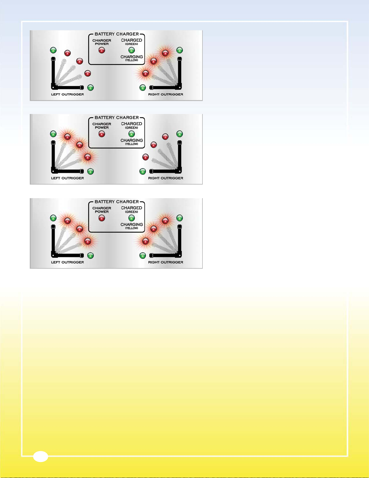
Figure 8 Outriggers Fully Retracted LED Indicators
Figure 9 Right Outrigger Extending LED Indicators
Outriggers Fully Retracted – The two lower green LEDs
will be illuminated when both outriggers are fully retracted.
The UniLift is in PALLET JACK mode and is capable of
lifting, lowering and transporting a palletized load as a
pallet jack.
Right Outrigger Extending – As the UniLift transitions
from a pallet jack to a stacker, the right 3 red LEDs will
scroll outward indicating the right outrigger’s direction of
movement. While depressing the UP button, the right
outrigger will rotate from the fully retracted position to the
fully extended position in approximately 3 seconds. During
this time the LEDs will continue to scroll outward.

9
Right Outrigger Extended – When the right outrigger
reaches its fully deployed position, the upper right green
LED will illuminate. At this time, the left outrigger is in the
fully retracted position, as indicated by the green LED.
Figure 10 Right Outrigger Extended LED Indicators
Figure 11 Left Outrigger Extending LED Indicators
Figure 12 Outriggers Fully Extended LED Indicators
Figure 13 Left Outrigger Retracting LED Indicators
Left Outrigger Extending – Immediately following
the right outrigger extension, the left 3 red LEDs will
scroll outward indicating the left outrigger’s direction of
movement. Continue to depress the UP button.
Figure 14 Right Outrigger Retracting LED Indicators
Outriggers Fully Extended – The two upper green LEDs
will be illuminated when both outriggers are fully extended.
The UniLift is now in STACKER mode and is capable of
lifting and positioning a palletized load.
Left Outrigger Retracting – As the UniLift transitions from
a stacker to a pallet jack, the forks will automatically stop
lowering and the left 3 red LEDs will scroll inward indicating
the left outrigger’s direction of movement. Continue to
depress the DOWN button.
Right Outrigger Retracting – Immediately following
the left outrigger retraction, the right 3 red LEDs will
scroll inward indicating the right outrigger’s direction of
movement. Continue to depress the DOWN button to
ensure both outriggers are fully retracted.
10
Figure 15 Right Outrigger Stopped Mid-Travel LED Indicators
Figure 16 Left Outrigger Stopped Mid-Travel LED Indicators
Figure 17 Outrigger Obstruction LED Indicators
Right Outrigger Stopped Mid-Travel – If the operator
releases the UP or DOWN button with the right outrigger
in between it’s fully retracted or fully deployed positions,
the right 3 red LEDs will stop scrolling and flash. Continue
to depress the UP or DOWN button to ensure the right
outrigger is either fully retracted or fully extended.
Left Outrigger Stopped Mid-Travel – If the operator
releases the UP or DOWN button with the left outrigger
in between it’s fully retracted or fully deployed positions,
the left 3 red LEDs will stop scrolling and flash. Continue
to depress the UP or DOWN button to ensure the left
outrigger is either fully retracted or fully extended.
Outrigger Obstruction – If either outrigger encounters
a pallet or floor obstruction which stops the outrigger’s
movement, all 6 red LEDs will flash (3 right LEDs followed
by 3 left LEDs). The LEDs will continue to flash until the
operator reverses the outrigger’s direction. CAREFULLY
remove the obstruction or reposition the UniLift to allow the
outriggers to rotate as required. For additional information
refer to the “OPERATING INSTRUCTIONS – Stacker
Mode/Pallet Obstruction” section of this manual.
Battery Charger LEDs – The battery charger has 2 LEDs to indicate the charger’s status. The left CHARGER POWER LED will illuminate when
the charger is plugged into AC power with an extension cord. The right CHARGING/CHARGED LED is dual color and will glow yellow while the
batteries are charging and green when the batteries are fully charged. Always ensure the key switch is turned to the OFF position while charging
the batteries. Discharged batteries will typically require four (4) to six (6) hours to completely recharge.
Before using the UniLift for the first time, plug an extension cord into the charger’s power cord and allow the batteries to completely charge. The
charger’s CHARGING/CHARGED will glow green when the batteries are fully charged. Disconnect the extension cord and push the plug back
into the recess. The UniLift is now ready for use. Before using the UniLift, make sure you are familiar with the SAFETY INSTRUCTIONS, the
OPERATING INSTRUCTIONS and are TRAINED. Only trained and authorized personnel shall be permitted to operate a UniLift.

11
OPERATING INSTRUCTIONS
General Instructions
The UniLift is designed for use with GMA style (48” long x 40” wide) pallets. Dimensions for a standard GMA pallet are identified below in Figure
18. As shown below, the total depth of a GMA pallet is approximately 5 inches (127 mm). For the UniLift to operate properly, the pallet height
should not exceed 5 ½ inches (140 mm). In many cases, extremely tall pallets, pallets with very thick bottom boards or pallets with damaged
bottom boards will prevent the outriggers from extending properly. The UniLift must be capable of lifting the bottom of the pallet to a minimum
height of 4 inches (102 mm) off the floor (the minimum height for the UniLift’s outriggers to rotate to their extended positions).
In addition to GMA style pallets, the UniLift is capable of lifting most skids, including postal skids.
Figure 18 GMA Pallet Dimensions
1. Turn the ON–OFF switch to the ON position. The PLC is similar to a computer and requires approximately 5 seconds to initialize before
operation.
2. Check the status of the outrigger position LEDs. Both outriggers should be in the fully retracted positions. If not, depress the DOWN
button to fully retract both outriggers.
Brake Operation
The UniLift is equipped with a parking brake designed to hold the lift in a desired position on a level surface. The UniLift’s brake operation is
illustrated in Figure 19.
1. To apply the brake, rotate the brake lever to the lower position by depressing the brake pedal with your foot. The brake pedal will remain in
the depressed position until released.
2. To release the brake, position your foot under the pedal and nudge the lever upward. The brake lever will rotate to the upper position
releasing the brake.
Figure 19 Brake Operation Figure 20 Pallet Jack Mode

12
Stacker Mode/Work Positioner Operation
The UniLift allows palletized loads to be transported like a pallet jack
then lifted like stacker. This unique transformation occurs when the
deployable outriggers rotate to their fully extended positions providing
load support while the UniLift continues to lift the load.
1. Always ensure others are well clear of the UniLift.
2. Depress and hold the UP button to raise the forks. The forks will
rise to full extension in approximately 3 seconds and stop.
3. To transition to stacker mode, release the UP button then
depress and hold the UP button again. The right outrigger will
rotate to the fully open position in approximately 3 seconds.
As previously described, the right outrigger LEDs scroll in the
direction of the outrigger movement. When the outrigger reaches
full extension, the green right outrigger extended LED will
illuminate. Extension of the left outrigger will start automatically.
Observe the left outrigger LED display, the red LEDs scroll
outward. If either outrigger strikes an obstruction and fails to
extend fully, both the right and left red LEDs will alternately flash
(see stacker operation/pallet obstruction).
4. After both outriggers reach full extension, the forks will continue
to rise. Continue to depress the UP button to raise the load to
the desired height. When the desired height is reached, release
the UP button.
5. Turn the ON–OFF switch to the OFF position and apply the
Pallet Jack Mode Operation
The UniLift is capable of operating like a pallet jack and will easily transport palletized loads on a smooth level surface.
1. Depress the DOWN button to ensure the forks are fully lowered.
2. Check the position of the brake. If required, rotate the brake pedal to the release position.
3. Insert the forks into a loaded pallet. Ensure the forks are centered in the pallet and fully engage the pallet. The pallet should be in good
condition with the load uniformly distributed on the top surface. ALWAYS visually check the condition of the load before attempting to raise
and move it.
4. Depress the UP button to raise forks and elevate the palletized load. Release the UP button when the bottom of the pallet clears the floor.
If a squealing sound is heard coming from the UniLift, immediately release the UP button. The pressure relief valve is operating due to an
overload. Reduce the load to 2000 lbs or less before attempting to lift it.
DANGER
ALWAYS travel with the outriggers retracted and the forks in the lowest position possible.
5. Carefully transport the palletized load to the desired location. Pull or push the UniLift slowly and avoid sharp turns or rapid maneuvering.
6. Whenever possible, pull the loaded UniLift to the desired location. To pull the UniLift, first lower the pull handle to a comfortable position
and grip the handle loop with both hands. Next, ensure you have a sure footing and then carefully pull on the handle to start the UniLift in
motion. Once the UniLift is in motion, release one hand, turn and face the desired direction while pulling with the other hand.
7. Always look ahead and walk slowly while pulling the UniLift. Take care when maneuvering around corners and in tight areas. Always
watch for others when traveling in narrow aisles or approaching intersections.
8. If pushing a load is required, place both hands on the handle and push slowly. Use care and avoid sudden steering movements.
9. Always keep an eye on the condition of the load. If the load shifts or becomes unstable, stop immediately and restack the load.
10. When the palletize load is at the desire location, depress the DOWN button to lower the forks.
11. With sure footing, carefully pull the UniLift rearward to remove the forks from the pallet.
WARNING
NEVER leave the loaded lifter unattended unless the forks are fully lowered, the brake is applied and the key switch is
turned to OFF.
Figure 21 Stacker Mode
s
parking brake.
6. Load or unload the pallet as required. Always uniformly distribute the load on the pallet surface and never exceed the capacity or load
center ratings.
7. Always use extreme care when working around a loaded pallet in the raised position. Never put hands or feet under the pallet or inside the
outriggers at any time.
WARNING
DO NOT overload the UniLift. NEVER exceed the designated capacity and load center ratings.
CRUSHING HAZARD - ALWAYS keep hands and feet clear of the load and all moving components.

13
8. If repositioning the pallet height is required, walk to the rear of the unit and turn the ON-OFF switch to ON. Wait 5 seconds, then raise or
lower the pallet to the desired height. Turn the ON-OFF switch to OFF, then continue loading or unloading as required.
9. When the loading or unloading process is complete, walk to the rear of the UniLift and turn the ON-OFF switch to ON. Depress and
hold the DOWN button to lower forks. The forks will lower to the transition point and the outriggers will automatically retract to the stored
position. Outrigger progress is displayed on the LED console. If either outrigger encounters an obstruction or fails to fully retract, the red
LEDs will flash (see stacker operation/pallet obstruction).
10. Release the DOWN button when the forks reach the desired height or are completely lowered.
DANGER
DO NOT travel with the load elevated. ALWAYS travel with the outriggers retracted and the forks in the lowest
position possible.
Stacker Mode/Positioning a Pallet (elevated surface 29 ½” high or less)
1. Follow the “Pallet Jack Mode Operation” instruction and position the palletized load directly in front of the elevated surface. The UniLift
should be positioned such that the pallet can be pushed into the desired position without turning the steering handle. Apply the parking
brake.
2. Depress and hold the UP button to raise the forks. The forks will rise to full extension and stop. Release the UP button then depress and
hold the UP button again. After both outriggers reach full extension, the forks will continue to rise. Continue to depress the UP button to
raise the load to the desired height above the elevated surface or platform. If possible, the bottom of the pallet should be 1” – 2” above the
elevated surface. When the desired height is reached, release the UP button.
CAUTION
DO NOT continue to operate the pump if a squealing noise is heard coming from the pump. The pressure relief valve
is operating. Continued use of the pump with the relief valve operating will cause permanent damage the pump. The
forks are at their maximum raised height.
3. Check to ensure there is sufficient clearance for the outriggers and that there is no obstruction in front of the unit.
4. Release the brake then slowly and carefully push the raised pallet over the elevated surface. Push straight and watch the condition of the
outriggers at all times.
If an outrigger strikes an obstruction or deflects from the extended position, STOP immediately and reverse direction. If possible,
lower the forks to pallet jack height and fully retract the outriggers. Completely lower the load, turn the ON-OFF switch to the
OFF position and remove the UniLift from service. Contact a supervisor or maintenance personnel to inspect the UniLift for
damage.
5. When the palletized load is properly positioned, depress the DOWN button to lower the load onto the elevated surface. Continue to lower
the forks until they completely disengage the pallet and release the DOWN button. Carefully pull the UniLift rearward to remove the forks
from the pallet.
6. When the forks are well clear of the pallet and elevated surface, depress and hold the DOWN button to lower forks to the fully lowered
position.
7. With the UniLift operating as a pallet jack, move the lift to the desired location.
Stacker Mode/Pallet Obstruction
As previously mentioned, the UniLift is designed for use with GMA style (48” long x 40” wide) pallets. In many cases, extremely tall pallets, pallets
with very thick bottom boards or pallets with damaged bottom boards will prevent the outriggers from extending properly. The UniLift must be
capable of lifting the bottom of the pallet to a minimum height of 4 inches (102 mm) off the floor (the minimum height for the UniLift’s outriggers to
rotate to their extended positions).
Outriggers fail to extend while raising a pallet
1. If either outrigger fails to extend while raising a pallet, the red LEDs from both sides will alternately flash indicating the outriggers have
contacted an obstruction.
2. Release the UP button and carefully look under the pallet to determine the nature of the obstruction.
3. If the pallet is in good condition but is too deep, then lower the pallet and remove the UniLift from the pallet. Temporarily place a thin board
on the top of each fork. The board should be approximately 6” wide and extend the full length of the fork. Carefully reinsert the UniLift forks
into the pallet. Before raising the load, ensure the boards are properly positioned on the forks.
4. Raise the pallet as normal. The boards (spacers) may elevate the pallet and create the required space for the outriggers to extend
normally.
5. Otherwise, if an obstruction is present and can be removed without placing a hand or foot under the pallet, remove the obstruction and
continue to operate the UniLift as normal.
6. If these procedures fail, the UniLift is not capable of lifting this pallet. Another lifting device must be used.
Outriggers fail to retract while lowering a pallet
1. If either outrigger fails to retract while lowering a pallet, the red LEDs from both sides will alternately flash.
2. Release the DOWN button and carefully look under the pallet to determine the nature of the obstruction.
3. Next, press the UP button and raise the pallet to a convenient height and carefully remove the obstruction. Never place a hand or foot
under the loaded pallet.
4. If the obstruction can not be removed, lower the forks to the lowest possible position and carefully travel to a location with an elevated

14
platform capable of supporting the loaded pallet. An ideal surface would be 18 – 24 inches (457 – 610 mm) in height and have clearance
for the outriggers at the floor. Lower the damaged pallet onto the surface and remove the UniLift. Another lifting device must be used.
ROUTINE MAINTENANCE
The UniLift is designed to provide years of trouble free service and requires very little maintenance. However, a routine inspection and
maintenance program will prevent costly replacement of parts and/or downtime. All service should be performed by a qualified service person who
has an understanding of load positioning equipment and electrical/hydraulic diagrams. This person should be thoroughly familiar with the operation
and use of this type of equipment.
DANGER
A falling load can cause SEVERE PERSONAL INJURY or DEATH. NEVER go under the loaded or unloaded forks.
All maintenance should be performed with the forks in the fully lowered position or securely blocked in a raised
position.
Use extreme care when handling or working around batteries. Improper handling can cause SEVERE PERSONAL
INJURY or DEATH.
ALWAYS use eye protection and protective clothing when handling batteries. Batteries contain acid which can cause
severe burns and injury.
NEVER expose a battery to extreme heat, open flames or sparks. Battery vapors are explosive.
WARNING
ALL lift servicing must be performed by qualified personnel only. Unauthorized modifications to the UniLift, its
hydraulic power unit or its control system may compromise the performance and safety of the system resulting in
SEVERE PERSONAL INJURY and PROPERTY DAMAGE.
UNDER NO CIRCUMSTANCES should you attempt any repair or service that is not covered in this manual.
DO NOT attempt to remove the constant force spring. The constant force spring is heavily preloaded and will recoil
violently if released.
ALWAYS remove the load and DEPRESS THE DOWN BUTTON for several seconds to release the hydraulic
pressure before servicing the lift. The release of hydraulic fluid under high pressure can be dangerous.
ALWAYS disconnect the battery before servicing the electrical system. Not doing so could result in a SEVERE
ELECTRICAL SHOCK.
Blocking the Forks in a Raised Position
Blocking the unloaded forks in an elevated position may be required for certain periodic inspections or maintenance operations. There are many
acceptable methods to block or secure the unloaded fork carriage in an elevated position. Identified below are several methods:
• Bishamon carriage support (recommended method) • Fork lift
• Overhead hoist or structure with sling • Portable scissor lift
• Heavy duty work platform approximately 32 inches high • Structural member securely positioned in the mast
Always use extreme care when blocking the unloaded forks in an elevated position. If an acceptable method is not available, Bishamon offers an
optional carriage support plate that will secure the elevated fork carriage to the top of the mast. Install the plate as follows:
1. Completely lower the forks and turn the key switch to the OFF position. Remove the mast top cap and disconnect the mast cover. Detailed
instructions are presented on the following pages.
2. Position the carriage support plate over the roll pins. Next, replace the center button head cap screw and tighten securely.
Figure 22 Handle Assembly Removal
3. Turn the key switch to the ON position and carefully lower the fork
carriage until the carriage support plate rests on top of the mast.
Install the hex bolt supplied with the bracket into the center hole on
top of the mast and tighten securely.
4. Finally, turn the key switch to the OFF position. The fork carriage is
now secured in an elevated position.
Removing the Upper Console and Lower Battery Cover
Tools required:
• 5/32 Hex L-Key (Allen) wrench or equivalent
• Two 1/2 inch sockets or wrenches
1. First, move the UniLift to an area with good lighting and a suitable
work area. Completely lower the forks and turn the key switch to
the OFF position. Next, using the two 1/2 inch sockets or wrenches,
remove the bolt and nut that secure the handle assembly to the
brake pivot shaft. As shown in Figure 22, pull the handle assembly
straight up off the brake pivot shaft and set it off to the side.

15
2. Using the Allen wrench, remove the four (4) screws attaching the console plate to the upper console cover. Next, remove the four (4)
screws that attach the upper console cover to the lower battery cover.
3. As illustrated in Figure 23, slide the console plate together with the upper console cover top end straight back about one (1) inch and
carefully separate the upper console cover from the console plate. Set the upper console cover off to the side.
4. Temporarily replace and snug the front two (2) screws to secure the console plate to the mast.
5. To remove the lower battery cover, remove the eight (8) screws that attach the lower battery cover to the frame.
6. As shown in figure 24, remove the lower battery cover by working it upwards and rotating the left side of the cover back such that the
electric cord can be disconnected from the battery charger. Disconnect the battery charger cord from the battery charger, finish removing
the cover and set it off to the side. Inspection and/or maintenance can now be performed on the UniLift.
Figure 23 Upper Console Cover Removal
Figure 24 Lower Battery Cover Removal
7. To reinstall the covers, install the lower battery cover first, then
the upper console cover.
Disconnecting the Batteries
1. Lower the forks completely and turn the key switch to the OFF
position.
2. Follow the instruction above to remove the lower battery cover.
As shown in Figure 25, locate the main power fuse attached
to the right battery. Unplug the fuse to disconnect all battery
power to the system.
3. When servicing is complete, plug the power fuse into the fuse
holder and reinstall the lower battery cover.
Disconnecting the Mast Cover
1. Lower the forks completely and turn the key switch to the OFF
position.
2. Using a 3/16 inch hex key wrench, remove the two (2) button
head cap screws that secure the top cover to the mast. Place
the mast top cover off to the side.
3. As shown in Figure 26, remove the button head cap screw and
the clamp plate. Set the screws and plate off to the side. Figure 25 Main Power Fuse

16
Daily Visual Inspection
Bishamon recommends that every UniLift be visually inspected daily before use. Detailed below is a suggested daily inspection checklist for normal
operating conditions and environments. Extreme or unusual operating conditions may require a more extensive inspection and maintenance
program. If you have any questions regarding the inspection or maintenance of any UniLift, do not hesitate to contact your local Bishamon dealer
or Bishamon Industries Corp. If any of the following conditions exist, REMOVE the UniLift from service and contact a qualified service person.
Inspect the following items with the forks lowered.
1. Visually check the general condition of the UniLift. Inspect for loose, worn, damaged or broken components.
2. Visually inspect the frame, mast, outriggers and fork carriage for broken or cracked welds.
3. Check the condition of the warning labels. The warning labels are for the safety of the operator. If the labels are worn, missing or
unreadable, REPLACE them before placing the UniLift back in service.
Inspect the following items with the forks fully raised.
1. Visually inspect the wheels and rollers (6 total) for flat spots, wear or damage.
2. Visually inspect the cylinder area for hydraulic fluid leakage.
3. As shown in Figure 28, manually operate both linkage lever arms and check for smooth movement and complete load wheel retraction. To
check their operation, first ensure the forks are fully raised and the key switch is turned to OFF. Carefully gasp each lever arm and rotate it
rearward until it stops. Release each arm and watch for smooth movement and complete load wheel retraction. There should be a definite
audible knock when the load wheel fully retracts and strikes the travel stop in the fork. If the load wheels fail to retract completely or any
binding is present, the lift MUST be repaired before continued use use or damage to the battery cover may result.
4. Grasp the mast cover on each side and slide the cover off the roll pins. Next guide the cover upward allowing the cover to retract. Similar
to a window shade, the mast cover will retract completely. When released, the roller may spin for several turns releasing the spring
tension.
5. When reinstalling the mast cover it will be necessary to re-tension the roller spring. To do so, turn the key switch to the ON position and
raise the forks to their maximum height. Take care not to put your hands or feet under the forks. Next, pull the cover downward and
reposition the holes over the pins on the fork carriage. Replace the clamp plate and screw. As demonstrated in Figure 27, lift the axle with
the flat end out of the slot. Using a pair of needle-nose pliers, rotate the axle clockwise five (5) full turns and place it back into the slot.
6. Finally, reposition the mast cap on top of the mast and reinstall the two screws. Raise and lower the forks several times to ensure the mast
cover functions correctly. If not, check the spring tension (step 5) and ensure the yellow mast cover is properly aligned with the roller.
Figure 26 Mast Cover Clamp Figure 27 Roller Installation
Figure 28 Linkage Lever Arms
Table of contents
Other Bishamon Forklift manuals


