EKKO EP20LI Series User manual

EP20LI
Service Manual
Warning
You must read the operation instruction before
using the manual:
•Please check the last page of this
document and all the current product
type identification on the nameplate.
•Keep it for future use.

目录
1. 维修清单 .............................................................................................Error! Bookmark not defined.
a. 主要零部件概述............................................................................................................................... 0
b. 润滑点 ............................................................................................................................................. 3
c. 检查再加注液压油 ........................................................................................................................... 4
d. 检查电器保险丝...............................................................................Error! Bookmark not defined.
2. 故障分析 .............................................................................................Error! Bookmark not defined.
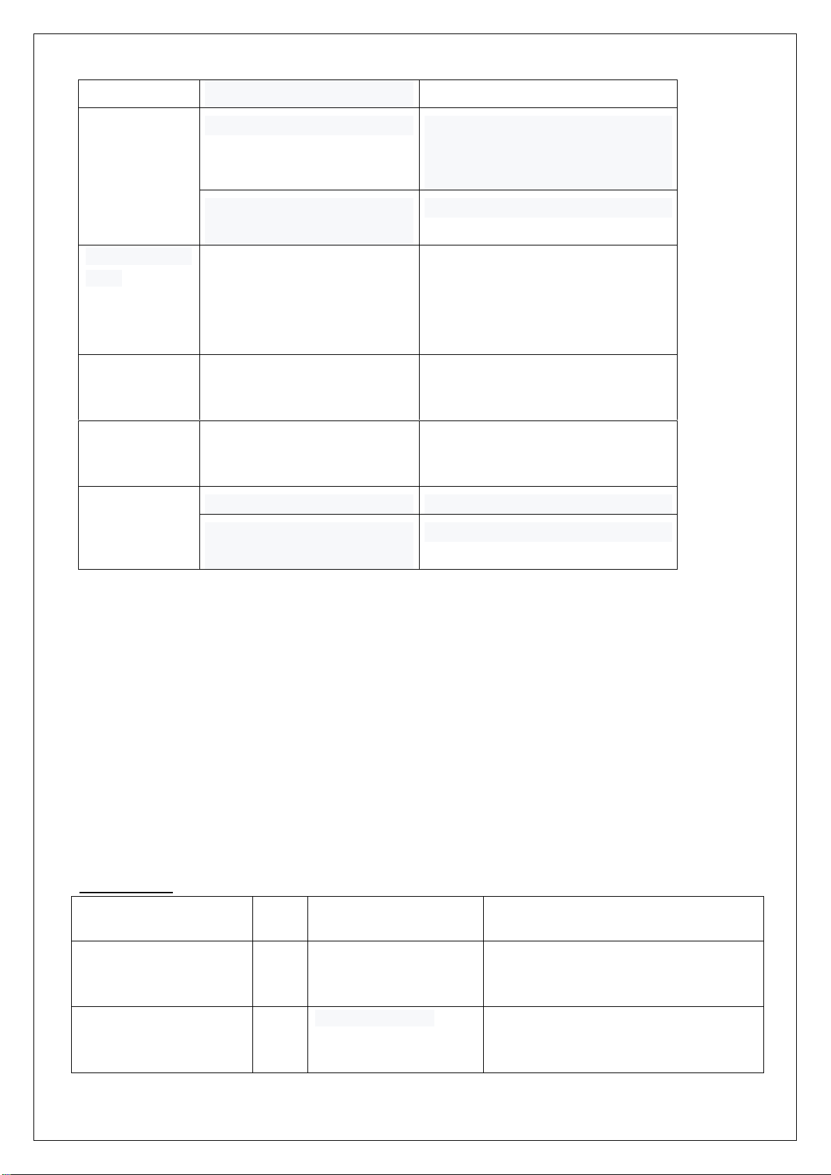
a. 常见故障分析................................................................................................................................... 5
b. 仪表故障代码显示 ...........................................................................Error! Bookmark not defined.
3. 接线/电路图.........................................................................................Error! Bookmark not defined.
a. 电路图 .............................................................................................Error! Bookmark not defined.
b. 液压回路........................................................................................................................................ 13
4. 主要零部件拆解 ..................................................................................Error! Bookmark not defined.
a. 电池刹车调整...................................................................................Error! Bookmark not defined.
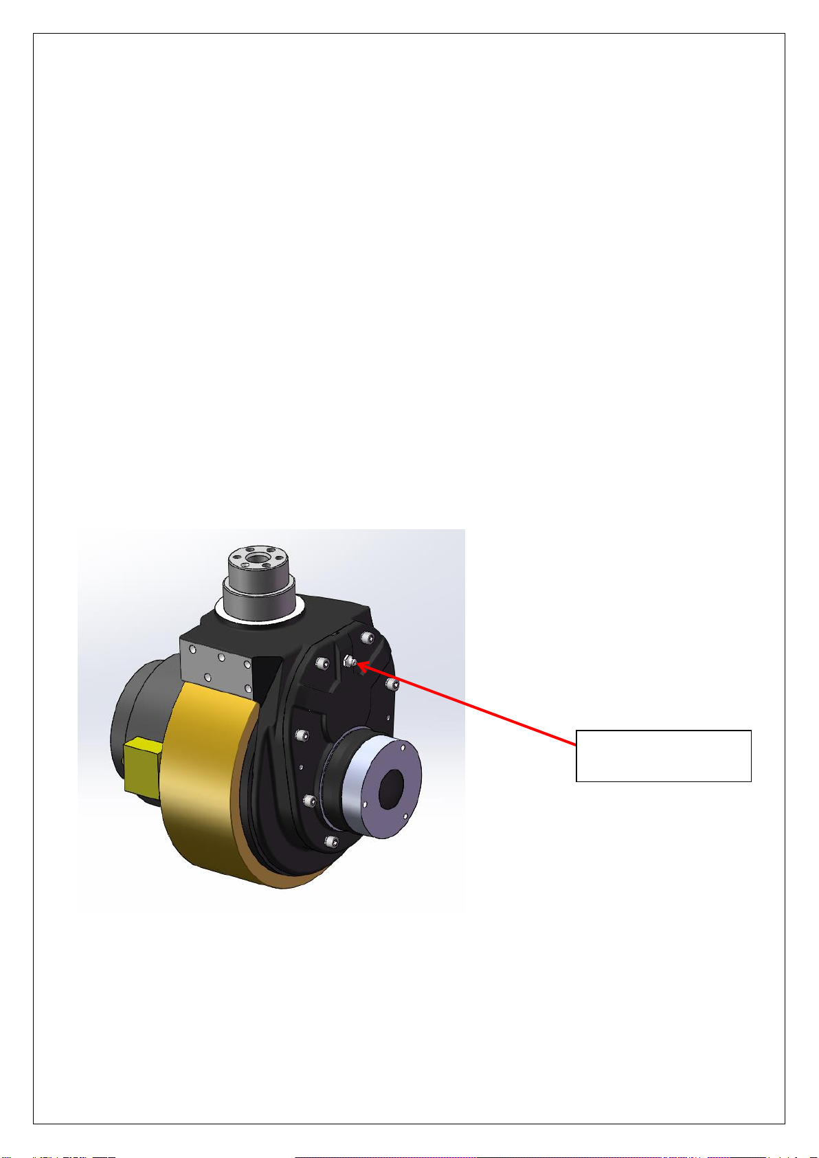
b驱动总成拆解...................................................................................Error! Bookmark not defined.
c. 驱动刹车拆解...................................................................................Error! Bookmark not defined.
d. 驱动内部齿轮 轴承 .........................................................................Error! Bookmark not defined.
e. 手柄总成..........................................................................................Error! Bookmark not defined.
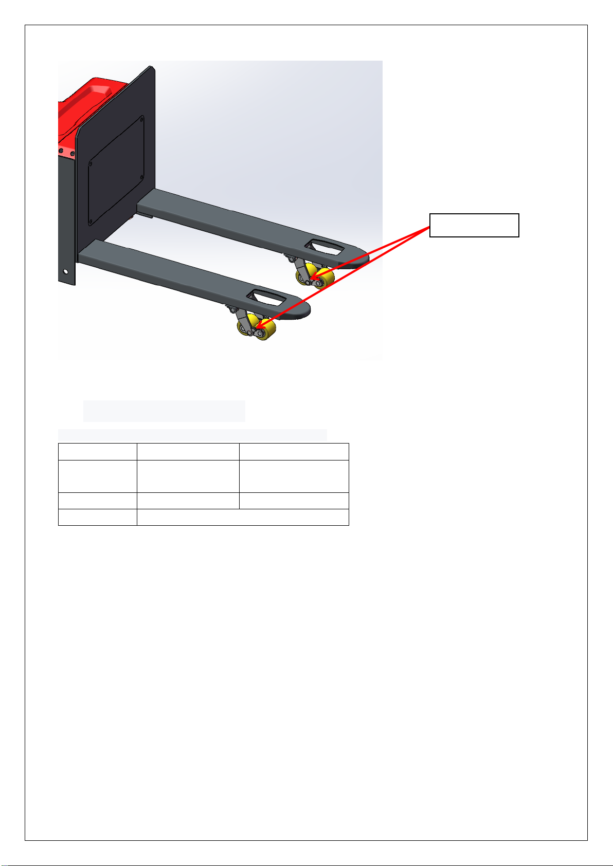
f. 车架分解..........................................................................................Error! Bookmark not defined.
g. 泵站电机..........................................................................................Error! Bookmark not defined.
5. CURTIS 手持单元 ............................................................................................................................. 14
1Regular maintenance
Only qualified and trained personnel should perform maintenance work on this

1
vehicle.
Before maintenance, remove the cargo from the fork and lower the fork to the
lowest position.
If you need to lift the vehicle, use the specified lashing or jacking equipment.
Before operation, place safety devices (such as designated jacks, wedges or
wood blocks) under the vehicle to prevent accidental drop, movement or sliding.
Use the original parts approved and released by your dealer.
Please consider that hydraulic fluid leakage may lead to machine failure and
accidents.
Pressure valve adjustment is only allowed by trained service technician.
If you need to replace wheels, casters must be round and free of abnormal wear.
Check the items on the maintenance list。
1. Maintain List
Time Interval
(Month)
1
3
6
12
hydraulic system
1.1
Check the function of hydraulic system
•
1.2
Check hoses, piping and joints for tightness, sealing and damage
•
1.3
Inspect cylinder block and piston for damage, sealing and fixation
•
1.4
Visually inspect the door stand roller and inspect the roller surface for wear
•
1.5
Inspect forks and loading parts for wear and loss
•
1.6
Check load chain Settings and re-tensioning if necessary
•
1.7
Check oil level in fuel tank
•
1.8
Replacement hydraulic fluid
•
mechanical system
2.1
Check the fork for deformation and breakage
•
2.2
Check chassis for deformation and cracking
•
2.3
Check that all screws are in place
•
2.4
Check gear box for noise and leakage
•
2.5
Check wheel for deformation and damage
•
2.6
Lubricated steering bearing
•
2.7
Check and lubricate the pivot points
•
2.8
Lubricating grease nozzle
•
Electric System
3.1
Check whether electrical wiring is damaged
•
3.2
Checking Electrical Connections
•
3.3
Check emergency switch function
•
3.4
Check electric drive system for noise and damage
•

2
3.5
Detection meter
•
3.6
Check that the correct fuse is used
•
3.7
Check alarm system and safety devices
•
3.8
Check the current contactor
•
3.9
Check frame for leakage (insulation test)
•
3.10
Check the function and wear of the drive controller
•
3.11
Check the electrical system driving the motor
•
traveling system
4.1
Check the gearbox for abnormal sound
•
4.2
Check the driving mechanism and grease it
•
4.3
Inspect driving and steering wheels for wear and damage
•
4.4
Check wheel bearing and fastening condition
•
4.5
Check the air gap of the electromagnetic brake
•
4.6
Check the lifting, forward and backward tilt and left and right movement of the
door frame
•
4.7
Check and adjust braking effect
•
energy supply
5.1
Check the voltage of the battery
•
5.2
Check that battery cables are securely connected and grease the electrodes if
necessary
•
5.3
Check whether the battery cover is damaged
•
5.4
Check the main cable for damage
•
5.5
Check the startup protection program during charging
•
monolithic component
6.1
Check all labels for clarity and completeness
•
6.2
Check the frame for damage
•
6.3
Check the fixing condition of lifting door frame
•
6.4
Run a test run
•

3
1.2 Lubrication points
Lubricate marked points according to maintenance list. Required grease specification: DIN 51825
standard grease.
Figure 1: Steering drive gear
Drive the oil injection
port

4
1.3Check and refill hydraulic oil
Recommended hydraulic oil model according to temperature:
Temperature
–5℃~25℃
>25℃
Model
HVLP 32,
DIN 51524
HLP 46,
DIN 51524
Viscosity
28.8-35.2
41.4 - 47
Oil volume
2L-2.5L
Waste materials such as waste oil, waste batteries or other materials must be treated and recycled in accordance
with national regulations, and returned to the recycling company for recycling if necessary.
The oil level should not be lower than the minimum amount required to start the vehicle.
Fill up to refueling point if necessary.
1.4Check the electrical fuse
Bearing shaft

5
10A fuse
fuse specification
specification
Fuse 1
10A
Fuse 01
200A
2. Malfunction Analysis
If the vehicle continues to malfunction, follow the instructions in the manual.
2.1Common fault analysis
Fault
Cause
Processing method
Vehicles
cannot move
The battery connector is not
connected
Check the battery connector and
connect it if necessary
The electric lock switch is in
"OFF" position
The electric lock switch is placed in
the "0" position
The emergency stop switch is
not on
Turn on the emergency stop switch
Battery running out
Check the charging status of the
battery and recharge it if necessary
The forklift is charging
Interrupt charging process
Fuse damage
Check fuse
Cargo cannot
be lifted
The vehicle is not running
Follow the procedure listed in the
"Vehicle cannot Move" fault
There's too little hydraulic fluid
Check hydraulic oil
Fuse damage
Check fuse
Load overweight
Note rated load
The lift micro switch is in bad
Check fuse
200A fuse

6
contact or damaged
Goods cannot
be lowered
Dirty oil clogs the control valve
Check the hydraulic oil and clean the
control valve and replace the
hydraulic oil if necessary
The descent solenoid valve is
not open or damaged
Check the drop solenoid or replace it
can't stop when
go up
The lifting micro switch
is damaged
Cut off the power supply and
replace the lifting micro
switch
Moving in one
direction
Contact between micro
switch and connecting
cable is not good
Check the micro switch and
connecting cable in the control
handle
Traffic moves
slowly
The battery power is low
or the corresponding
cable is in poor contact
Check the battery indicator and
corresponding cables
The vehicle
started
suddenly
Controller damage
Replacing a Controller
Control forward and backward
handle is not reset
To restore or replace
2.2 Display of fault code
Table 4:1212P fault codes
Programmer display
code
The fault
phenomenon
fault diagnosis
BATTERY DISCONNECT
FAULT
4.5
Battery disconnection
1) Battery disconnection
2) Poor contact of battery end
BRAKE OFF FAULT
3.4
Brake closing fault
1)Electromagnetic brake coil short
circuit

7
2)Electromagnetic brake drive open
circuit
BRAKE ON FAULT
3.2
Brake opening failure
1) Electromagnetic brake coil open
2)Electromagnetic brake drive short
circuit
CURRENTSENSE FAULT
4.1
Current detection fault
1) Short circuit of motor or motor
wiring
2)The controller is faulty
EEPROM CHECKSUM
FAULT
4.3
EEPROM failure
1) EEPROM failure or invalid
HARDWARE FAILSAFE
4.2
Motor voltage is out of
range
1) Motor voltage cannot match
accelerator input
2) Short circuit of motor or motor
matching ring
3) The controller is faulty
HPD FAULT
3.5
HPD fault
1) Accelerator, key switch, promotion
or prohibition
Input several actions out of order
2) Wrong adjustment of accelerator
MAIN FAULT
2.3
The main contactor is
faulty
1) Main contactor adhesion or open
2) Main contactor coil drive error
MAIN OFF FAULT
2.1
Main contactor coil drive
'off' failure
1) Wrong opening of main contactor coil
MAIN ON FAULT
2.4
Main contactor coil drive
'on' failure
1) The main contactor coil is closed
incorrectly
OVERVOLTAGE FAULT
1.5
Battery voltage is too
high
1) Battery voltage >31V
2) The charger is still connected when
the vehicle is running
3) Poor battery contact
PRECHARGE FAULT
3.3
Pre charge failure
1) The controller is faulty
2) Low battery voltage
SPEED POT FAULT
1.3
The speed limiting
potentiometer is faulty
1) Open or short circuit connection of
speed limiting potentiometer
2) Open speed limiting potentiometer
THERMAL FAULT
1.1
Over/under temperature
cut-off
1) Temperature >80℃or <-10℃
2) Vehicle overload
3) Operate in extremely harsh
environment

8
4) The electromagnetic brake is not
released normally
THROTTLE FAULT
1.2
Potentiometer slip end
or low
1) Accelerator input is open or short
2) Accelerator potentiometer failure
3) Wrong selection of accelerator type
UNDERVOLTAGE FAULT
1.4
The terminal voltage is
out of range
1) Battery voltage <17V
2) The battery or controller is
not connected properly
Methods for troubleshooting common faults.
Code 4.5 The battery is not connected.
1. Check whether the fastening of cable terminals of the car body is loose, as shown below:
1、Use a multimeter to measure the monomer voltage of the battery with load. The specific operation is
shown as follows:
Check whether the cable connection (including other secured parts) is
loose
Cell with load measurement, cell voltage drop should be
between 2 and 3V

9
3 Circuit/circuit diagram
3.1Electrical schematic diagram
(Dc normal handle)

10
code
English name
中文名称
12
Controller Overcurrent
控制器过流
13
Current Sensor
电流传感器故障
14
Precharge Failed
预充失败
15
Controller Severe
Undertemp
控制器温度过低
16
Controller Severe Overtemp
控制器过温
17
Severe B+ Undervoltage
B+欠压
17
Severe KSI Undervoltage
KSI 欠压
18
Severe B+ Overvoltage
过压
19
Speed Limit Supervision
最大速度受限
1A
Travel Control Supervision
行走控制监控异常
22
Controller Overtemp
Cutback
控制器过温导致性能降低
23
Undervoltage Cutback
控制器欠压导致性能降低
24
Overvoltage Cutback
控制器过压导致性能降低
25
Ext 5V Supply Failure
5V电源故障
26
Ext 12V Supply Failure
12V电源故障
28
Motor Temp Hot Cutback
电机过热导致性能降低
29
Motor Temp Sensor
电机温度传感器故障
31
Main Driver
主接触器驱动异常
32
EM Brake Driver
电磁刹车驱动异常
35
Proportional Driver
比例阀驱动异常
36
Encoder Fault
电机编码器故障
37
Motor Open
电机开路
38
Main Contactor Welded
主接触器主触点粘连
39
Main Contactor Did Not
Close
主接触器不吸合
42
Throttle Input
加速器输入异常
46
NV Memory Failure
控制器存储异常
47
HPD Sequencing
(上电)操作顺序故障
47
EMER Rev HPD
紧急反向操作顺序故障
49
Parameter Change
参数修改故障
4A
EMR Switch Redundancy
紧急反向开关冗余异常
51
User_1_Fault
(上电)紧急反向有效
52
User_2_Fault
(上电)互锁有限
53
User_3_Fault
BMS 报文超时
54
User_4_Fault
锂电故障
55
User_5_Fault
锂电过温告警
56
User_6_Fault
锂电过温故障
57
User_7_Fault
锂电漏液告警
58
User_8_Fault
锂电漏液故障
59
User_9_Fault
前拓CAN仪表通讯故障

11
61
User_10_Fault
前拓CAN仪表低电量
62
User_11_Fault
前拓CAN仪表继电器开路
68
VCL Run Time Error
程序或参数设置异常
72
PDO Timeout
PDO超时
73
Stall Detected
电机堵转
77
Supervision
(外部)监控故障
87
Motor Characterization
Error
电机匹配故障
88
Encoder Pulse Error
电机编码器脉冲异常
89
Parameter Out Of Range
参数超限
92
EM Brake Failed To Set
电磁刹车松闸失败
94
Emer Rev Timeout
紧急反向超时
99
Parameter Mismatch
参数不匹配
A1
Driver 1 Fault
驱动1故障(下降电磁阀)
A2
Driver 2 Fault
驱动 2故障 (电磁刹车)
A3
Driver 3 Fault
驱动3故障(主接触器)
A4
Driver 4 Fault
驱动4故障
A5
Driver 5 Fault
驱动 5故障(起升接触器)

12
(Ac normal handle)

13
3.2Hydraulic diagram

14
Hydraulic oil inspection
appearance
smell
situation
The results of
Clear and non-discoloration
good
good
You can use
Color transparent
good
Mix with other oils
Check viscosity, if qualified
can continue to use
The color changes like milk
good
Mixed with air and water
Separate moisture or replace
hydraulic oil
The color turns dark brown
bad
oxidation
Replacement of hydraulic
fluid
The color is clear but there are
small black spots
good
Mix it with other particles
Use after filtering
4、Disassembly of main parts
a、electromagnetic brake adjustment
adjusting nut
Electromagnetic brake clearance is about
0.25-0.35mm, about the thickness of a piece
of paper. Need to be adjusted carefully
repeatedly, ensure that three adjustment
surface clearance is consistent, electricity
will give out a crisp sound.
Note: electromagnetic brake
can't pull properly when it is
powered on in free state, it
needs external force or
installation to pull

16
c、Handle assembly
5、CURTIS Handheld unit
Precautions for operation:
The attention function of the hand-held unit is to facilitate vehicle inspection and maintenance. It is not
allowed to adjust the controller parameters without the approval of the vehicle manufacturer, to avoid
vehicle and personal safety accidents.
The hand-held unit will automatically save the modification parameters, just need to close the key switch,
restart.
The CURTIS handheld unit can be connected in the event of a controller power or power failure.
Vehicle fault reading process:
1. After connecting the handheld unit with the controller, open the key switch
2, From the menu list of CURTIS handheld units, find: Faults...
3. When the vehicle is running and the hand-held cursor flashes, there will be English fault content, which
can be interpreted by referring to the fault code table
Vehicle signal detection:
1. After connecting the handheld unit with the controller, open the key switch
2, According to the menu list of CURTIS handheld unit, find: Monitor......
3. According to requirements, open the corresponding sub-item of the detection menu, run the vehicle, and
Accelerator button
Belly switch
horn button
accelerator
Tortoise speed switch

17
observe the change of the hand-held value.
。
CURTIS Contents of handheld unit menu:
The Curtis 1313 handheld programmer is used to configure the Curtis electric control system. Through this programmer,
you can adjust and save the set parameters, real-time monitoring of controller data and fault diagnosis.
The programmer has two interfaces, one is used to communicate with the electric control, the other is used to
communicate with the PC, the programmer has a battery box and a memory card slot
The programmer is powered on.
The connection line of the handheld programmer can be connected to the controller by inserting the programming port
of the controller. After connecting the controller, the handheld programmer will be powered on automatically and the
control information will be displayed on the programmer.
Warning: The control system can affect the vehicle's
acceleration rate, deceleration rate, hydraulic
system, and braking. A dangerous situation can
occur if the vehicle control system is not
programmed correctly or exceeds safety. Only the
vehicle manufacturer or an authorized service agent
can program the control system.

18
Menu structure
The main menu consists of nine sub-menus, and each sub-menu is displayed with a specific icon. Each item in the
The function keys
Since the function of the three keys is determined by the
specified content, the three keys are blank. At any given
time, the function of the button is displayed on the LCD
screen above.
Direction arrow key
The displayed information can be selected up, down, or left
by four directional buttons.
+ / - buttons
You can add and subtract parameters by using these two
keys. In addition, "+" can mean "Yes" and "-" can mean
"No”. In some cases, it can also be used as a scrolling
option.
Power key
When the programmer inserts a controller that has been
powered on, the programmer does not have to press the
power button to use it. The programmer will start up
automatically. When you hold it down for a few seconds, the
programmer will prompt you whether to turn it off. You can
decide whether to turn it off by selecting the "Yes" and "No"
represented by the function key. After closing the
programmer, press for a few seconds and the programmer
will restart.
Collect keys
There are two ways to enter the Favorites menu. You can
enter Favorites from the main menu or press this key
Table of contents
Other EKKO Forklift manuals

EKKO
EKKO EB20E User manual

EKKO
EKKO EK18A-189LI Service manual

EKKO
EKKO EK07S Series User manual

EKKO
EKKO EK13 User manual

EKKO
EKKO EK15A-189LI Series User manual

EKKO
EKKO EPE20LI Series User manual

EKKO
EKKO EA15B User manual

EKKO
EKKO EK20LI Series User manual

EKKO
EKKO EA15 Series User manual

EKKO
EKKO EOP68 User manual