8
6190900 (Rev B) 87R-4P Compressor System User Guide
© 2017, JUN-AIR
We reserve the right to make any alterations which may be due to any technical improvements
Printed in the USA
WARNING
DO NOT install the system on a surface with an incline that
exceeds 10°.
WARNING
If unit is operating at a high altitude, adjustments to the
duty cycle (on time) or operating pressure may be required.
Consult a service technician prior to making any adjustments.
WARNING
A leaking pressure relief valve may indicate a need for
adjustment or repair. Consult a service technician prior to
making any adjustments.
Protection Against Electrical Shock
Provide proper grounding per NFPA 70 (NEC 2008). Do
not create a current path from the equipment to ground
through your body.
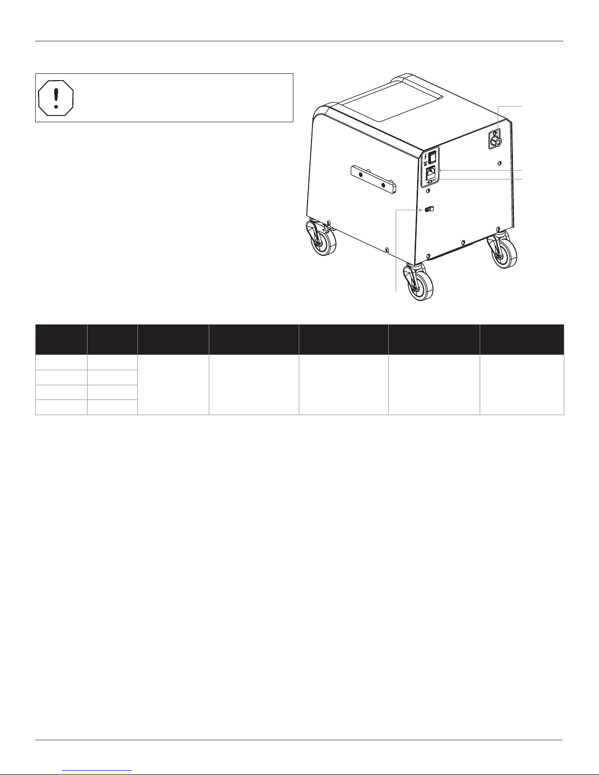
Electrical Safety
• Verify that the voltage and frequency specified on the
system are the same as that of the supply power.
• Never operate unit outside the specified voltage range
(see “SITE REQUIREMENTS” for range).
• See “SPECIFICATIONS” for more electrical information.
• Indicator light on the system cover displays when sys-
tem power is supplied and power switch is on.
Electromagnetic Interference (EMI):
The JUN-AIR system is designed to avoid electromagnetic
emissions interference with surrounding electrical
equipment. Due to the vast assortment of electrical
equipment available, it is possible that some interference
may be experienced by the end customer. If interference
is experienced, the device that is creating interference
should be removed from the room where the compressor
system is located. If the interference persists, then it
may be necessary to confirm that both devices are
connected to isolated (separated) circuits per “ELECTRICAL
CONNECTIONS” in this manual. If the problem still occurs,
then the two devices should be moved as far apart as
possible. Finally, if the problem cannot be eliminated,
contact JUN-AIR.
CAUTION
Routinely inspect any and all power cords for cuts and
abrasions. Discontinue use and have an authorized service
representative replace cord if damaged.
WARNING
Use of an extension cord is not advisable. An undersized
extension cord will cause a drop in line voltage and loss of
power. Overheating may result. Death or fire from electrical
shock could occur.
WARNING
Electric shock could occur as a result of improper
grounding. This product must be grounded
according to NEC regulations and all local codes
WARNING
Always switch system off and remove power when servicing
or removing the electrical cover. Lock out power at the breaker
prior to servicing.
CAUTION
Do not plug into an ungrounded outlet or adapter. Reliable
earth ground can only be achieved when system is connected
to a grounded receptacle.
WARNING: To Avoid Serious Burns,
do not touch surface during operation and allow it
to cool prior to servicing.
WARNING
Electrical Shock Hazard
The grounding wire is indicated by green insulation or
green insulation with yellow stripes.
Install this product in a dry location.
Install this product where it will be weather protected.
This product must be properly grounded. Electrically
ground this product per local codes.
Check the condition of the power supply wiring.
Do not permanently connect this product to wiring that is
not in good condition or is inadequate for the requirements
of this product.
Follow all local applied codes prior to installation.
Failure to follow these instructions can result
in death, fire, or electrical shock.