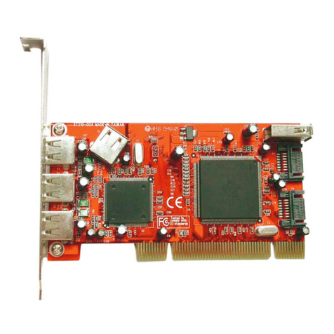
BitFlow The Karbon-CL Quick user guide

Preliminary
The Karbon-CL
Hardware Reference Manual
BitFlow, Inc.
300 Wildwood Ave
Woburn, MA 01801
USA
Tel: 781-932-2900
Fax: 781-933-9965
Email: support@bitflow.com
Web: www.bitflow.com
Revision F.0

Preliminary
© 2006 BitFlow, Inc. All Rights Reserved.
This document, in whole or in part, may not be copied, photocopied, reproduced, trans-
lated or reduced to any other electronic medium or machine readable form without the
prior written consent of BitFlow, Inc.
BitFlow, Inc. makes no implicit warranty for the use of its products and assumes no
responsibility for any errors that may appear in this document, nor does it make a commit-
ment to update the information contained herein.
BitFlow, Inc. retains the right to make changes to these specifications at any time without
notice.
All trademarks are properties of their respective holders.
Revision History:
Revision Date Comments
F.0 2006-09-01 First Printing

Preliminary
Table of Contents
BitFlow, Inc.
Table of Contents
P - Preface
Purpose KBN-P-1
Support Services KBN-P-1
Technical Support KBN-P-1
Sales Support KBN-P-1
Conventions KBN-P-2
1 - General Description and Architecture
The Karbon-CL family KBN-1-1
Virtual vs. Hardware KBN-1-1
The Virtual Frame Grabber (VFG) KBN-1-1
Karbon Configuration Spaces KBN-1-2
Firmware, Camera Files and Downloads KBN-1-5
General Description KBN-1-6
The Full CL Virtual Frame Grabber (Full CL VGF) KBN-1-7
The Base CL Virtual Frame Grabber (Base CL VGF) KBN-1-8
The Karbon-CL Models KBN-1-11
2 - Acquisition and Camera Control
Introduction KBN-2-1
BitFlow’s Flow-Thru Architecture KBN-2-2
Camera Specific Firmware KBN-2-5
Generation of Acquisition Windows KBN-2-7
The Horizontal Active Window, HAW KBN-2-7
The Vertical Active Window, VAW KBN-2-8
The Control Tables (CTABs) KBN-2-10
Vertical Control Table KBN-2-10
The VCTAB Functions KBN-2-11
Horizontal Control Table KBN-2-13
The HCTAB Functions KBN-2-15
Synchronizing Acquisition, Camera, CTABs and External Signals KBN-2-18
Vertical Operations and Events KBN-2-18
Horizontal Operations and Events KBN-2-22
Acquisition Command and Status KBN-2-26
The Acquisition Bitfields KBN-2-26
Trigger Processing KBN-2-31
Encoder Processing KBN-2-32
The On-Board Signal Generator KBN-2-33

Preliminary
Table of Contents
BitFlow, Inc.
3 - System Status
Introduction KBN-3-1
FACTIVE, FCOUNT KBN-3-2
PCOUNT, LCOUNT, FENCOUNT KBN-3-3
RD_TRIG_DIFF/TTL/OPTO, RD_ENC_DIFF/TTL/OPTO KBN-3-4
VCOUNT, HCOUNT, LINES_TOGO KBN-3-5
FIFO_EQ KBN-3-6
DEST_ADD KBN-3-7
4 - Camera Control Registers
Introduction KBN-4-1
Bitfield definitions KBN-4-2
Example Bitfield Definition KBN-4-2
Bitfield Definition Explanation. KBN-4-2
CON0 Register KBN-4-4
CON1 Register KBN-4-8
CON2 Register KBN-4-15
CON3 Register KBN-4-21
CON4 Register KBN-4-24
CON5 Register KBN-4-31
CON6 Register KBN-4-37
CON7 Register KBN-4-39
CON8 Register KBN-4-41
CON9 Register KBN-4-46
CON10 Register KBN-4-50
CON11 Register KBN-4-54
CON12 Register KBN-4-56
CON13 Register KBN-4-58
CON14 Register KBN-4-60
CON17 Register KBN-4-64
CON18 Register KBN-4-66
CON19 Register KBN-4-68
CON20 Register KBN-4-70
CON21 Register (Bayer Version) KBN-4-73
CON23 Register KBN-4-76
CON24 Register KBN-4-78
CON25 Register KBN-4-82
CON26 Register KBN-4-84
CON27 Register KBN-4-85
CON36 Register KBN-4-86
CON37 Register KBN-4-88
CON38 Register KBN-4-90
5 - Karbon/Neon DMA Registers
Introduction KBN-5-1

Preliminary
Table of Contents
BitFlow, Inc.
CON28 Register KBN-5-2
CON29 Register KBN-5-4
CON30 Register KBN-5-6
CON31 Register KBN-5-8
CON32 Register KBN-5-10
CON33 Register KBN-5-13
6 - Register and Memory Mapping
Introduction KBN-6-1
Memory Types KBN-6-2
Registers KBN-6-2
UART KBN-6-2
DPM KBN-6-2
TAG KBN-6-2
CTABs KBN-6-2
Memory Map KBN-6-3
Downloading Firmware KBN-6-5
PCI Configuration Space and Model/Revision Information KBN-6-6
Scatter Gather DMA Instructions KBN-6-7
Destination Address KBN-6-8
Size of Transfer KBN-6-9
Next Quad Address KBN-6-10
7 - Electrical Interfacing
Introduction KBN-7-1
Trigger KBN-7-2
Trigger Input Types KBN-7-2
The Optocoupled Trigger KBN-7-2
Encoder KBN-7-4
Encoder Input Types KBN-7-4
The Optocoupled Encoder KBN-7-4
General Purpose Inputs (GPIN) KBN-7-6
General Purpose Outputs (GPOUT) KBN-7-7
The Open Collector Drivers for GPOUT5 and GPOUT6 KBN-7-7
Camera Link Controls (CCs) KBN-7-11
8 - Specifications
Introduction KBN-8-1
Maximum Pixels Per Line KBN-8-2
Maximum Lines Per Frame KBN-8-3
Power Consumption KBN-8-4

Preliminary
Table of Contents
BitFlow, Inc.
9 - Mechanical
Introduction KBN-9-1
The Karbon-CL Connectors KBN-9-3
The CL Connectors KBN-9-3
The I/O Connector KBN-9-4
The Auxiliary Connectors KBN-9-4
The Jumpers and Switches KBN-9-5
Jumpers KBN-9-5
Switches KBN-9-7
The Camera Link Connector Pinouts (CL1 to CL4) KBN-9-8
The I/O Connector Pinout (P11) KBN-9-9

Preliminary
Preface Purpose
Version F.0 BitFlow, Inc. KBN-P-1
Preface
Chapter P
P. 1 Pu r p o s e
This Hardware Reference Manual is intended for anyone using the Karbon-CL frame
grabber. The purpose of this manual is two-fold. First, this manual completely
describes how the board works. Second, it is a reference manual describing in detail
the functionality of all of the board’s registers.
P.1.1 Support Services
BitFlow, Inc. provides both sales and technical support for the Karbon family of prod-
ucts.
P.1.2 Technical Support
Our web site is www.bitflow.com.
Technical support is available at 781-932-2900 from 9:00 AM to 6:00 PM Eastern Stan-
dard Time, Monday through Friday.
please include the following:
Product name
Camera type and mode being used
Software revision number
Computer CPU type, PCI chipset, bus speed
Operating system
Example code (if applicable)
P.1.3 Sales Support
Contact your local BitFlow Sales Representative, Dealer, or Distributor for information
about how BitFlow can help you solve your most demanding camera interfacing
problems. Refer to the BitFlow, Inc. website (www.bitflow.com) for a list of North
American representatives and worldwide distributors.

Preliminary
Purpose The Karbon
KBN-P-2 BitFlow, Inc. Version F.0
P.1.4 Conventions
Table P-1 shos the conventions that are used for numerical notation in this manual.
Table P-2 shows the numerical abbreviations that are used in this manual.
Table P-1 Base Abbreviations
Base Designator Example
Binary b 1010b
Decimal None 4223
Hexidecimal h 12fah
Table P-2 Numeric Abbreviations
Abbreviation Value Example
K 1024 256K
M 1048576 1M

Preliminary
General Description and Architecture The Karbon-CL family
Version F.0 BitFlow, Inc. KBN-1-1
General Description and Architecture
Chapter 1
1.1 The Karbon-CL family
The purpose of this chapter is to explain, at a block diagram level, how the Karbon-CL
works, and what different versions are available. There are four main models in the
Karbon-CL family:
KBN-PCE-CL2-D, supports two base CL cameras
KBN-PCE-CL2-F, supports one medium, full or 10-tap CL camera
KBN-PCE-CL4-D, supports four base CL camers
KBN-PCE-CL4-F, supports two medium, full or 10-tap CL cameras
The differences between the models are explained in more detail in Section 1.4.
1.1.1 Virtual vs. Hardware
It’s important to understand how this manual works. Some chapters of this manual dis-
cuss the Karbon-CL as a hardware platform (this chapter is a good example). While
other chapters discuss the details of the virtual frame grabbers (VFG) that this hard-
ware platform supports. The concept of the virtual frame grabber is described below,
but basically the idea is that one hardware platform can support more than one
device. In the case of the Karbon-CL, these devices are frame grabbers.
Note that we are not using the word virtual here in the sense of “a software virtualiza-
tion of a hardware device”, these VFGs are real hardware. The reason we using “vir-
tual” is because the term “frame grabber” has more than one meaning. It can mean
the piece of hardware that you put in your computer, or it can mean the device that
the your software application is controlling and getting images from. For the pur-
poses of this manual, “virtual frame grabber” means the device that your application
is interfacing to. While this might sound complicated, the implementation is simple.
You plug our Karbon-CL frame grabber into your PC, and your application interacts
with one or more VFGs available. Everything else is taken care of by the BitFlow driv-
ers.
1.1.2 The Virtual Frame Grabber (VFG)
The Karbon family is the first board from BitFlow that supports the concept of the vir-
tual frame grabber (VFG). The idea behind the VFG is to separate the hardware plat-
form (connectors, laminate, FPGAs, etc.) from the frame grabbing functionality that
software applications work with. The primary reason behind this separation is that the
turn around time for hardware is much longer than the turn around time for modifying
virtual frame grabbers. To create a brand new vitual frame grabber, or to modify an
exising one, simply requires writing new firmware or updating existing firmware.

Preliminary
The Karbon-CL family The Karbon
KBN-1-2 BitFlow, Inc. Version F.0
The idea of modifying a frame grabber by making changes to its firmware is not new.
BitFlow has been doing this since its very first product. However, what is new about
the Karbon family, is the fact the entire frame grabber is written in firmware. The only
fixed hardware components are the interfaces to the outside world (e.g. the CL chips
on the front end). Everything else that makes up the board, camera control, data buff-
ering, DMA engine, etc. is written in firmware. This gives the Karbon plaform incredi-
ble levels of flexiblity and opens the door to unlimited customization.
To understand which models support which modes see Section 1.4. Also to see exam-
ples of the different modes, see Section 1.3. However, keep in mind, the Karbon is
only limited by your imagination, if you need a mode you don’t see, just let us know.
1.1.3 Karbon Configuration Spaces
The four basic Karbon-CL boards support from one to four VFGs. Each VFG has its
own configuration space (PCI interface) and will look like a separate device to the
operating system. Each VFG will be connected to one or more CL interface chips. Fig-
ure 1-1shows the block diagram of the “D” models. The D models support base two
or four base CL cameras. Figure 1-1 shows the diagram of the F models, which sup-
port one or two medium, full or 10-tap CL cameras. Of cousre, F models support base
cameras as well.

Preliminary
General Description and Architecture The Karbon-CL family
Version F.0 BitFlow, Inc. KBN-1-3
Figure 1-1 KBN-PCE-CL2-D and KBN-PCE-CL4-D
KBN-PCE-CL4-D only
CL
Connector
2
Channel
Link
Chip
PCI
Device
0
PCI
Device
1
PCI
Device
2
PCI
Device
3
Channel
Link
Chip
Channel
Link
Chip
Channel
Link
Chip
PCI Express Bus
CL2
CL
Connector
3
CL3
CL
Connector
4
CL4
CL
Connector
1
CL1

Preliminary
The Karbon-CL family The Karbon
KBN-1-4 BitFlow, Inc. Version F.0
Figure 1-2 KBN-PCE-CL2-F and KBN-PCE-CL4-F
KBN-PCE-CL4-F only
CL
Connector
2
Channel
Link
Chip
PCI
Device
0
PCI
Device
1
Channel
Link
Chips
Channel
Link
Chip
Channel
Link
Chips
PCI Express Bus
CL2
CL
Connector
3
CL3
CL
Connector
4
CL4
CL
Connector
1
CL1

Preliminary
General Description and Architecture Firmware, Camera Files and Downloads
Version F.0 BitFlow, Inc. KBN-1-5
1.2 Firmware, Camera Files and Downloads
Note that all the devices present on a Karbon will appear in SysReg as separate Bit-
Flow Boards Found. The order that the VFGs appear in SysReg is determined by the
operating system and is somewhat arbitrary. However, SysReg list the connector(s)
associated with each VFG, so that the connection can be made between VFG and
physical connected camera.
Recall that, even though Karbon may appear like four frame grabbers, there is only
one actual hardware platform. For this reason the firmware of the of the VFGs on one
board is linked. The selection of the master VFG, determines the configurations of all
of slave VFGs. For example, if you have a KBN-PCE-CL2-D and you configure the mas-
ter VFG with a two-tap odd/even pixel camera, then the slave VFG will also have to be
configure for a two-tap odd/even pixel camera. In all other ways, however, the two
configurations do not have to match. If you have a requirement where this rule must
be broken, please contact BitFlow’s support department. Custom combinations of
firmware are available.
If there is a mismatch between the firmware required by one VFG’s camera file and
the firmware required by another VFG’s camera file, the master VFG’s firmware will
get priority. In practice this means that if you change the camera file for the master
VFG, and it requires different firmware than is already on the board, new firmware will
be downloaded next time you start an application. However, in the case of a slave
VFG, if different firmware is required than is on the board, an error message will pop
up indicating the problem. Thus all the camera files for a all the VFGs on one Karbon
should all require the same firmwarre. That said, if you have a custom need for a par-
ticular arrangement of cameras, please let us know. We can create custom firmware to
solve almost any problem.

Preliminary
General Description The Karbon
KBN-1-6 BitFlow, Inc. Version F.0
1.3 General Description
The Karbon-CL is a x8 PCI Express board. It can work in any PCI Express slot that it can
fit it. Usually this means an x8 or x16 slot. However, some mother boards have x4 slots
with x8 connectors. The Karbon-CL will work in these slots, although performance my
be somewhat reduced.
Figure 1-3 shows the block diagram of the Karbon-CL hardware platform. Recall that
this platform is available in a number of configurations. The block diagrams of the cur-
rent supported configurations is shown in Figure 1-3. Subequent sections discussed
the details of the various models.
Figure 1-3 Karbon-CL Hardware Platform
As discussed previously, the Karbon platform can support a number of different vir-
tual frame grabber arrangements. Thus the hardware resources seen in Figure 1-3 can
be utilized in a number of different ways.
KBN-PCE-CL4 only
64
Camera Control,
Data formatter,
FIFO,
PCI Interface,
Scatter-Gather
DMA Engine
CL
Connector
3
Channel
Link
Chip
Channel
Link
Chip
Channel
Link
Chip
Channel
Link
Chip
Channel
Link
Chip
Channel
Link
Chip
PCI Express Bus
CL3
CL
Connector
2
CL2
CL
Connector
1
CL1
CL
Connector
4
CL4

Preliminary
General Description and Architecture General Description
Version F.0 BitFlow, Inc. KBN-1-7
The Karbon-CL is offered in two major configuration: the KBN-PCE-CL4, which sup-
port up to four base CL cameras or two full CL cameras, and the KBN-PCE-CL2, which
supports up to two base CL cameras or one full CL camera. The final D or F in the
model number determines whether the board supports base CL cameras only (i.e. the
D models) or medium and full models (i.e. the F models). The following sections dis-
cuss these different virtual frame grabbers in more detail.
1.3.1 The Full CL Virtual Frame Grabber (Full CL VGF)
Figure 1-4 illustrates the Full CL virtual frame grabber (VFG) that is support on the Kar-
bon-CL hardware. Since the Full CL interface requires two CL connectors, the KBN-
PCE-CL2-F can only support one of these virtual frame grabbers, and the KBN-PCE-
CL4-F can support two of these virtual frame grabbers.
Figure 1-4 Full CL Virtual Frame Grabber
The Full CL VFG implements the Camera Link full configuration, i.e. it can accept a sin-
gle camera putting out up to 64 bits of data. In addition, it also supports the 10 tap
extension to the full CL spefication. This extension allows for the acquisition of up to
80 bits on two CL connectors. Not the the full VFG also supports base and medium CL
cameras.
80 64
64
64 64
64
64
64
Camera Link
Interface
MUX
Video Pipeline,
Data Packer
PCI Interface,
Scatter-Gather
DMA Engine
Camera
Control,
CTABs
FIFO
?? KB
I/O,
Triggers,
Encoders
UART
Serial
Interface
??
CL1
CL2
Local Bus
PCI Express Bus

Preliminary
General Description The Karbon
KBN-1-8 BitFlow, Inc. Version F.0
The Full CL VGF can accept input data at up to 85 Mhz.
The following paragraphs are a short description of each block.
The Camera Link Interface block implements the CL full configuration This block has
the Channel Link ICs, the Camera Control drivers and the serial communication tran-
ceivers.
The MUX block packs and assembles the data from the Camera Link block before it is
pushed into the FIFO. This block re-arranges on-the-fly the data from the camera’s
taps so that the data is written in raster scan format in the host memory.
The FIFO block, ?? Kilobytes deep, decouples the camera from the DMA engine. It is
implemented with dual ported memories.
The Camera Control block handles both camera synchronization as well as external I/
O. The block contains the CTABs which are uses to synchronize acquisition with the
camera, determine which pixels/lines get acquired and which do not, generate con-
trol signals to the camera and to extenal devices. This block also handls start/stoping
acquisition based on triggers and encoders.
The PCI interface block handles host reads/writes to/from the board. These reads/
writes are used to program the board, and to control its modes. This block is also
responsible for DMAing image data to the host memory (or other devices). The DMA
engine uses chaining scatter-gather DMA, which can DMA a virtually unlimited
amount of data to memory without using any CPU cycles.
There is an on-board UART, as required by the CL specification. There is only one
UART on the Karbon platform. It can be switch between the various CL connectors for
programming each camera in turn.
The IO connector block has transmitters/receivers to communicate with external
industrial equipment (triggers, encoders, light strobes etc.).
CL1 and CL2 are the two Camera Link connectors. CL1 is the main Camera Link con-
nector. It carries data bits 0-23, Camera Controls and serial data port. CL2 is the auxil-
iary connector. It carries data bits 24-63, for the full mode and bits 24-79 in ten-tap
mode.
1.3.2 The Base CL Virtual Frame Grabber (Base CL VGF)
Figure 1-5 illustrates the Full CL virtual frame grabber (VFG) that is support on the Kar-
bon-CL hardware. Since the Base CL interface requires one CL connectors, the KBN-
PCE-CL2-D can support two of these virtual frame grabbers, and the KBN-PCE-CL4-D
can support four of these virtual frame grabbers.

Preliminary
General Description and Architecture General Description
Version F.0 BitFlow, Inc. KBN-1-9
Figure 1-5 Base CL Virtual Frame Grabber
The Base CL VFG implements the Camera Link base configuration, i.e. it can accept a
single camera putting out up to 24 bits of data.
The Base CL VGF can accept input data at up to 85 Mhz.
The following paragraphs are a short description of each block.
The Camera Link Interface block implements the CL base configuration This block has
the Channel Link IC, the Camera Control drivers and the serial communication tran-
ceivers.
The MUX block packs and assembles the data from the Camera Link block before it is
pushed into the FIFO. This block re-arranges on-the-fly the data from the camera’s
taps so that the data is written in raster scan format in the host memory.
The FIFO block, ?? Kilobytes deep, decouples the camera from the DMA engine. It is
implemented with dual ported memories.
24 64
64
64 64
64
64
64
Camera Link
Interface
MUX
Video Pipeline,
Data Packer
PCI Interface,
Scatter-Gather
DMA Engine
Camera
Control,
CTABs
FIFO
?? KB
I/O,
Triggers,
Encoders
UART
Serial
Interface
??
Local Bus
PCI Express Bus
CL1

Preliminary
General Description The Karbon
KBN-1-10 BitFlow, Inc. Version F.0
The Camera Control block handles both camera synchronization as well as external I/
O. The block contains the CTABs which are uses to synchronize acquisition with the
camera, determine which pixels/lines get acquired and which do not, generate con-
trol signals to the camera and to extenal devices. This block also handls start/stoping
acquisition based on triggers and encoders.
The PCI interface block handles host reads/writes to/from the board. These reads/
writes are used to program the board, and to control its modes. This block is also
responsible for DMAing image data to the host memory (or other devices). The DMA
engine uses chaining scatter-gather DMA, which can DMA a virtually unlimited
amount of data to memory without using any CPU cycles.
There is an on-board UART, as required by the CL specification. There is only one
UART on the Karbon platform. It can be switch between the various CL connectors for
programming each camera in turn.
The IO connector block has transmitters/receivers to communicate with external
industrial equipment (triggers, encoders, light strobes etc.).

Preliminary
General Description and Architecture The Karbon-CL Models
Version F.0 BitFlow, Inc. KBN-1-11
1.4 The Karbon-CL Models
There are two models in the Karbon-CL family, the KBN-PCE-CL2 and the KBN-PCE-
CL4. Table 1-1 illustrates the capablitlites of each model.
Note that the R64 and R64e frame grabbers from BitFlow support acquisition from
two cameras in what is known as dual base mode. Dual base mode requires that the
two cameras be identical, and that they be synchronized. The Karbon-CL platform,
supports multiple cameras in a completely independent fashion. This means there
there are no restrictions on the type or resolutions of the cameras that you connect to
the same Karbon. There are also no restrictions on the synchronization between the
cameras. Not only do they no need to be syncrhonized, they don’t even need to be
acquiring at the same time. As far as your application is concerned each camera con-
nected to the Karbon-CL has it’s own independent frame grabber.
Table 1-1 Karbon-CL Models
Capability KBN-PCE-
CL2-D
KBN-PCE-
CL2-F
KBN-PCE-
CL4-D
KBN-PCE-
CL4-F
Number of base CL cameras supported 2 1 4 2
Number of medium CL cameras supported 0 1 0 2
Number of full CL cameras supported 0 1 0 2
Number of 10 tap full CL cameras supported 0 1 0 2
Number of Virtual Frame Grabbers supported 2 1 4 2
Maximum number of input bits 80 80 160 160
Number of independent trigger inputs 2 2?? 4?? 4??
Number of independent encoder inputs 2 4?? ?? ??
Number of PCI configurations (devices) 2 1 4 1

Preliminary
The Karbon-CL Models The Karbon
KBN-1-12 BitFlow, Inc. Version F.0
This manual suits for next models
2
Table of contents
Other BitFlow PCI Card manuals
Popular PCI Card manuals by other brands
Lava
Lava Dual Parallel-PCI installation manual
StarTech.com
StarTech.com PEX2S553B Spec sheet
Shift838
Shift838 838-PEB Version 1.0 manual
DAQ system
DAQ system PCIe-AIO14 user manual
Sun Microsystems
Sun Microsystems Sun FastEthernet PCI Adapter Installation and user guide

Hawking
Hawking WP251 Specifications
