BKT Elektronik AL200 User manual

BKT Elektronik - Headquarter
Poland, Lochowska 69 Str.
86-005 Biale Blota
Phone: +48 52 36 36 750
© 2022 BKT Elektronik
www.bkte.pl
BKT AL200
Electronic locking & monitoring swinghandle
with mechanical override
- user manual
- version 3

www.bkte.pl
AL200 swinghandle manual
2
Table of contents
1Introduction..........................................................................................................................................................................................................3
1.1 General information.................................................................................................................................................................................3
1.2 Device characteristics...............................................................................................................................................................................3
1.3 Working modes ........................................................................................................................................................................................3
2Technical specifications ........................................................................................................................................................................................ 4
3Assembly...............................................................................................................................................................................................................5
3.1 Package Contents .....................................................................................................................................................................................5
3.2 Dimensions............................................................................................................................................................................................... 5
3.2.1 Swinghandle dimensions........................................................................................................................................................... 5
3.2.2 AR221 reader dimensions..........................................................................................................................................................5
3.2.3 Cut out dimensions....................................................................................................................................................................6
3.2.4 Cogwheel dimensions................................................................................................................................................................ 6
3.2.5 Cam dimensions ........................................................................................................................................................................6
3.3 Single point assembly...............................................................................................................................................................................7
3.4 Multi-point assembly................................................................................................................................................................................ 7
3.5 Connectors ...............................................................................................................................................................................................8
4Standalone mode..................................................................................................................................................................................................9
4.1 Connection ...............................................................................................................................................................................................9
4.2 Master card programming......................................................................................................................................................................10
4.3 Adding new user card.............................................................................................................................................................................11
4.4 Removing user card................................................................................................................................................................................ 11
4.5 Removing all user cards..........................................................................................................................................................................11
4.6 LED signalling..........................................................................................................................................................................................12
5Operation mode in the access control system....................................................................................................................................................12
5.1 Connection .............................................................................................................................................................................................12
5.2 Electrical opening ...................................................................................................................................................................................13
5.3 Handle position indication...................................................................................................................................................................... 13
5.4LED signalling..........................................................................................................................................................................................14
6Accessories .........................................................................................................................................................................................................14
7Document revisions ............................................................................................................................................................................................15

www.bkte.pl
AL200 swinghandle manual
3
1Introduction
1.1 General information
Warning:
This is a Class A product. In a domestic environment this product may cause radio interference in which case the user may be required to take
adequate measures.
The specification is owned and copyrighted by BKT Elektronik Sp. z o.o. Information contained herein may be changed at owner’s discretion
without any notice. BKT Elektronik may not be held liable for any possible inaccuracies and discrepancies in this document.
1.2 Device characteristics
The AL200 is an electronic swinghandle for ICT cabinets. It allows opening of cabinet doors in a standard mechanical way and by electrical remote
control. It can operate with any access control system. Together with optional card reader it can also work as a stand-alone access control system.
Thanks to the installed cylinder, it is also possible to open it in an emergency with a key.
Basic features:
Possibility to work autonomously or in the access control system.
Two connectors providing control and status signals of the handle and for the optional fid card reader.
Equipped with the optical sensor of the handle position.
Three-color LED signalling the operation status of the swinghandle.
Emergency key override.
Available inserts for the master key system.
For use with indoor cabinets.
Installation in a standard 150x25mm cut out.
Can be installed in a single and multi-point locking system (requires additional elements - cam or cogwheel mechanism, which should
be ordered separately).
1.3 Working modes
In the current version (manufacturing date from Q2 2022, see chapter 6 Accessories), the handle can work in one of three modes:
1. Standard mechanical handle
If the electronic opening functionality is not used, the handle works as a standard mechanical handle
opened with a key. This solution is used when the cabinet is to be equipped with access control at a
later time.
2. Stand-alone access control system
Any card reader or keyboard with Wiegand interface can be connected directly to the handle. The
handle together with an optional reader creates an autonomous access control system. It is possible
to assign 63 identifiers (cards or PIN codes) of users who will be able to open the handle. Read more
in chapter 4 Standalone mode.
3. Work in the access control system
In this mode, the handle works only as an electronic mechanism that opens the cabinet. It is
compatible with any access control system. The external access controller controls the opening of
the handle. Information about the status of the handle (tilted/not tilted) can be transferred to the
superior controller. Read more in chapter 5 Operation mode in the access control system.

www.bkte.pl
AL200 swinghandle manual
4
2Technical specifications
Handle data
Parameter
Value
Power supply voltage
Nominal 12V DC, allowed 10-24V DC, recommended power supply 12V DC ≥500mA.
If the handle powers an optional card reader, take into account the supply voltage and the current
consumption of the reader.
Quiescent current consumption
(not including optional card
reader)
110 mA at 10 V
90 mA at 12 V
60 mA at 24 V
Maximum current consumption
when opening/closing (200ms)
(not including optional card
reader)
300 mA at 10 V
250 mA at 12 V
150 mA at 24 V
Connectors
Type 53047-0810 8-pin connector, type 53047-0410 4-pin connector
Dimensions
177 x 37 x 51mm (H x W x D)
Weight
150g
Packaging dimensions
200 x 100 x 50 mm (W x D x H)
Packaging weight
200g
Operating conditions
Temperature: 0°C - 50°C, Humidity: 0% - 90% RH (without condensation)
Storage conditions
Temperature: -10°C - 60°C, Humidity: 0% - 95% RH (without condensation)
Enclosure material
Glass fibre reinforced polyamide PA6 GF30
Enclosure colour
Black, RAL 9005
Enclosure protection degree
IP30
Compliance with directives
2014/30/EU (EMC), 2011/65/EU (RoHS)
Compliance with standards
EN 61000-4-2:2009 Electrostatic discharge immunity test.
EN 61000-4-3:2007 Radiated, radio-frequency, electromagnetic field immunity test
EN 61000-4-4:2012 Electrical fast transient/burst immunity test.
EN 61000-4-5:2014 Surge immunity test.
EN 61000-4-6:2014 Immunity to conducted disturbances, inducted by radio-frequency fields.
EN 61000-6-4:2007/A1:2011 Electromagnetic compatibility (EMC) –Emission standard for industrial
environments.
Part number
122AL002000
Optional AR221 reader data
Parameter
Value
Power supply voltage
Nominal 12V DC, allowed 6,5-30 V DC
Maximum current consumption
50mA
Working frequency
125kHz
Reading distance
4cm
Cable length
0.4m
Data for optional reader of any type
Parameter
Value
Reader type
The handle supports any type of reader that has a Wiegand interface. It can be a 125kHz card reader
(Unique, HID Prox etc.), 13.56MHz cards (Mifare, HID iClass etc.), biometric reader, keyboard reader etc.
Supported communication
interfaces
Wiegand 26bit - 66bit
Reader supply voltage
The handle has a connector for powering the reader. The reader is powered by the same voltage as the
handle, so it is necessary to select the value of the supply voltage appropriate for the handle and also for
the optional reader.
Maximum allowable power
consumption by the reader
200mA

www.bkte.pl
AL200 swinghandle manual
5
3Assembly
The swinghandle can work in a single-point system (only with a cam) or a multi-point system (with a cogwheel mechanism and a cam). The
package does not contain all the mounting elements. Additional mounting elements dedicated to the respective cabinet must be ordered
separately.
3.1 Package Contents
Packaging
AL200 swinhandle
Fastening element
with screw
Quick Start Guide
3.2 Dimensions
3.2.1 Swinghandle dimensions
3.2.2 AR221 reader dimensions
Mounting hole
Make a hole in the door at such a distance
from the swinghandle that the length of
the reader cable will enable connection.

www.bkte.pl
AL200 swinghandle manual
6
3.2.3 Cut out dimensions
3.2.4 Cogwheel dimensions
3.2.5 Cam dimensions
or

www.bkte.pl
AL200 swinghandle manual
7
3.3 Single point assembly
1
122AL002000
AL200 swinghandle
2
Fastening element with screw
3
122AM002021
Cap
4
122AM002022
Cap adapter
5
122AM002023
Cap screw F4.1x12
6
122AM002024
Cam bolt M6x8
7
122AM002100
Cam h=0mm (locking height H=18mm)
3.4 Multi-point assembly
1
122AL002000
AL200 swinghandle
2
Fastening element with screw
3
122AM002001
Cogwheel mechanism
4
122AM002002
Cogwheel mechanism adapter
5
122AM002003
Bushing for cam
6
122AM002004
Cam bolt M6x16
7
122AM002005
Cogwheel screw F4.1x22
8
122AM002006
Cam h=0mm (locking height H=24mm)
1
2
4
3
5
7
6
1
2
4
3
6
8
7
5
www.bkte.pl
AL200 swinghandle manual
8
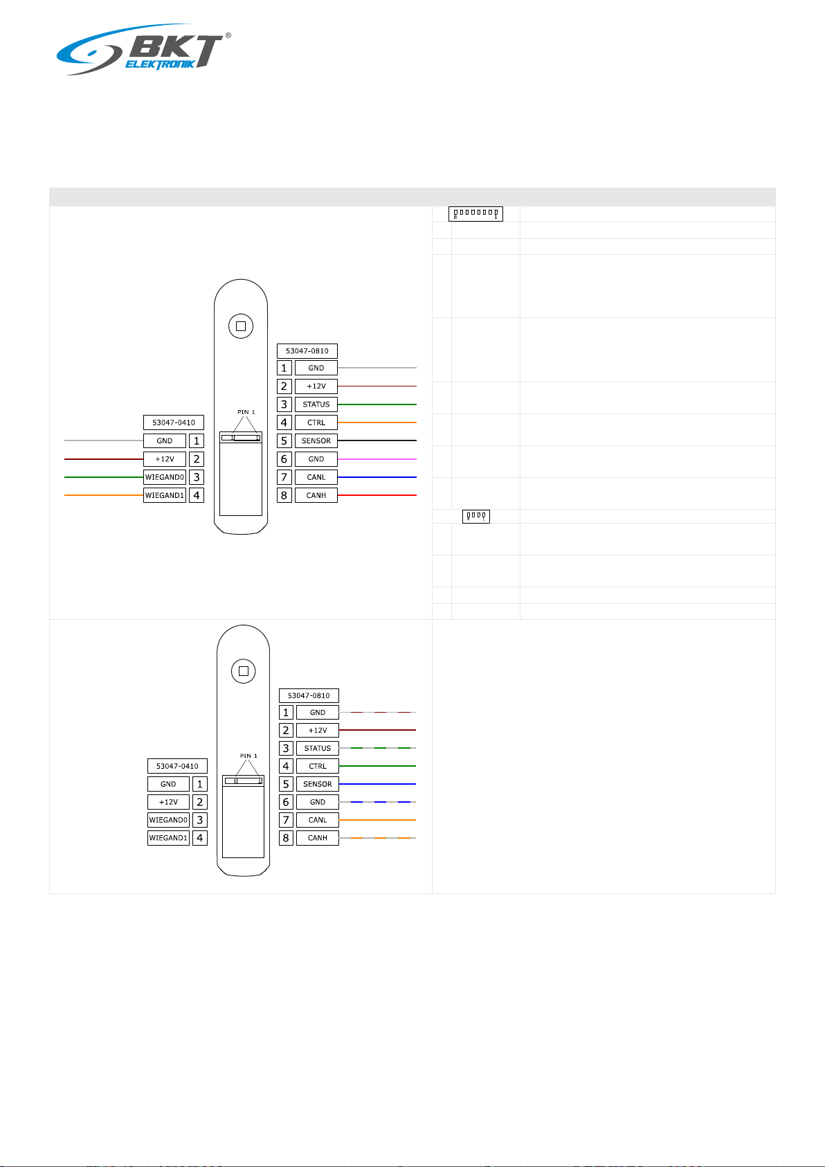
3.5 Connectors
The handle has two connectors: 8-pin and 4-pin. The 8-pin connector is the basic connector that provides power and control signals for the
handle. The 4-pin connector is dedicated only to the optional card reader. The table below describes the individual pins of the connectors. The
given colours apply to the LiYY type cable, eg AW285 and AW240 (see chapter 6 Accessories).
Connectors
8-pin socket type 53047-0810
1
GND
Power supply input: GND.
2
+12V
Power supply input: +12V.
3
STATUS
Open collector output for signalling the position of
the handle, IC=50mA, UCE=25V.
Handle open -> transistor on,
handle closed -> transistor off.
4
CTRL
Input for controlling the swinghandle from an
external system.
Opening the handle -> CTRL shorted to GND or +12V,
Closing the handle -> CTRL not connected.
5
SENSOR
Door sensor input
- for the future use. Do not connect.
6
GND
GND - for the door sensor
- for the future use. Do not connect.
7
CANL
CAN bus interface (CANL)
- for the future use. Do not connect.
8
CANH
CAN bus interface (CANH)
- for the future use. Do not connect.
4-pin socket type 53047-0410 for rfid card reader
1
GND
Card reader power supply output
(directly connected to GND of 8-pin socket).
2
+12V
Card reader power supply output
(directly connected to +12V of 8-pin socket).
3
WIEGAND 0
Wiegand 0 card reader input.
4
WIEGAND 1
Wiegand 1 card reader input.
white
brown
green
yellow
grey
pink
blue
red
4-pin socket
8-pin socket
AW240 cable
AW285 cable
white
brown
green
yellow
white-brown
brown
white-green
green
blue
white-blue
orange
white-orange
8-pin socket
UTP AW205
cable

www.bkte.pl
AL200 swinghandle manual
9
4Standalone mode
A dedicated AR221 reader (see chapter 6 Accessories) or any other card reader with
a Wiegand interface can be connected to the handle. A handle with a connected reader
creates an autonomous access control system. It enables the assignment of 63 user IDs
who will be able to open the handle. The process of assigning user cards is performed
with the use of the master card. The process of creating a master card is described
below. All card assigning procedures are performed without the use of a computer.
4.1 Connection
Connection diagram of two handles with readers in the cabinet
Devices used (see chapter 6 Accessories)
1
AL200 swinghandle
122AL002000
2
AR221 card reader
122AR002210
3
Any reader with Wiegand interface
-
4
AW240 cable
122AW002400
5
AW285 cable
122AW002850
6
Power supply 12V 1.5A
122AA100015
7
DC power cord
122AA100016
8
AC power cord
11480784.2
9
Junction box
122AA100006
Connection diagram of the handle with the reader in standalone mode
The handle 8-wire cable can be extended to a maximum length of 100m with selecting the appropriate cross-section of the wire. The maximum
allowed length of the reader cable is 3m.
+
or
or
or
1
2
3
4
5
9
7
8
6
Reader with
Wiegand
interface
Power supply
12VDC 1.5A
white
brown
green
yellow
grey
pink
blue
red
Unused wires must
be insulated.
4-pin socket
8-pin socket
AW240 cable
AW285 cable
white
brown
green
yellow

www.bkte.pl
AL200 swinghandle manual
10
4.2 Master card programming
The master card is used for user card programming. It allows to add a new user or delete an existing one. Before programming, prepare a card
suitable for a given type of reader. For the dedicated AR221 it is the EMC-1 card (see chapter 6 Accessories).
Note: Programming a new master card deletes all previously saved user cards.
Action
State after performing the action
1
Prepare a card that will be the master card.
2
Disconnect the power from the handle.
3
Open the handle with a key.
4
Reconnect the power to the handle and wait 3 seconds until the green LED on the handle lights
up continuously.
5
Close the handle when the green LED is on, then the green LED will start blinking (2Hz).
The green LED is on for 5 seconds. If the handle is not closed within this time, it will return to
normal operation.
6
Touch the prepared master card to the reader when the green LED is blinking.
The green LED flashes for 5 seconds. Correct programming of the user card will be signalled by
the green LED lighting for 2 seconds. The master card will be programmed and all user cards will
be deleted. When the green diode is flashing and the master card is not applied, the handle will
return to the normal operating state and the existing user cards will not be removed from the
memory.
7
Wait 3 seconds for the handle to restart.
Keep the master card in a safe place.

www.bkte.pl
AL200 swinghandle manual
11
4.3 Adding new user card
The procedure saves to the memory the user card that will be able to open the handle.
Action
State after performing the action
1
Check if the user card has already been saved in the memory. Touching an unsaved card to the
reader should cause the red LED to flash once.
2
Touch the master card to the reader. The green LED should start blinking (2Hz) for 5 seconds.
3
While the green LED is blinking, apply a new user card.
Correct programming of the user card will be signalled by the green LED lighting for 2 seconds.
If the red LED lights up for 2 seconds, it means that the user card memory is full. You must then
remove a single card (see chapter 4.4 Removing user card) or delete all saved cards (see chapter
4.5 Removing all user cards).
4.4 Removing user card
The procedure removes a single user card from memory. The removed card will not open the handle.
Action
State after performing the action
1
Check if the user card is already saved in the memory. Touching the written card to the reader
should open the handle.
2
Touch the master card to the reader. The green LED should start blinking (2Hz) for 5 seconds.
3
While the green LED is blinking, touch the card to be removed from memory.
4
Make sure the card does not open the handle anymore - the red LED should flash once.
4.5 Removing all user cards
To remove all user cards, use the master card programming procedure (see chapter 4.2 Master card programming).
www.bkte.pl
AL200 swinghandle manual
12
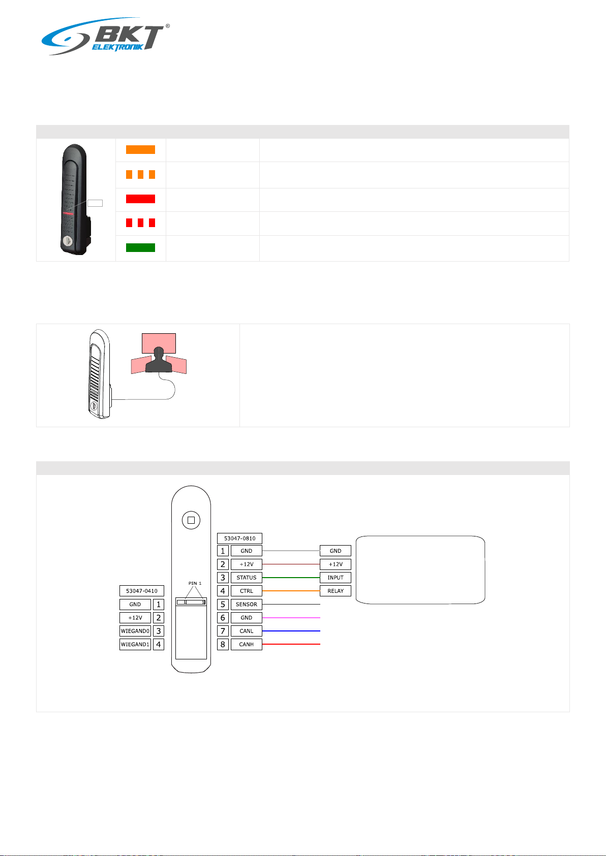
4.6 LED signalling
The handle has a three-color LED indicating the operating status. The basic operating states are summarized in the table below. The particular
LED signalling is described in the individual master and user card programming procedures.
LED state
Swinghandle working state
Orange is on
The device is in programming mode.
Orange blinking (1Hz)
The device is booting (within 3 seconds after connecting the power)
or firmware error (if it blinks for more than 3 seconds).
Red is on
The electric lock of the device is closed and handle is closed.
Red blinking (1Hz)
The electric lock of the device is closed, but the handle is open.
Green is on
The electric lock of the handle is open for 2 seconds after touching the
authorized user card.
5Operation mode in the access control system
The handle can work as only a cabinet door opening mechanism in a larger access
control system. It can cooperate with any access control system, eg BKT ACS or any
other company. The handle should be connected to the access controller that controls
its operation. The handle can transmit information to the controller about the current
position of the handle (tilted/not tilted).
5.1 Connection
Connection diagram of the handle with the external access control system
The handle connection cable can be extended to a maximum length of 100m using eg. UTP cat.5e twisted pair.
LED
External access
controller
white
brown
green
yellow
grey
pink
blue
red
Unused wires must
be insulated.
4-pin socket
8-pin socket
AW285 cable
Power supply for external devices
Input for handle position
Relay or OC control output

www.bkte.pl
AL200 swinghandle manual
13
5.2 Electrical opening
Electric opening is made by shorting the CTRL input to the GND or +12V potential. If the CTRL input is not connected anywhere, then the
swinghandle remains closed.
CTRL input state
Swinghandle lock status
CTRL input not
connected
Lock is closed
CTRL input not
connected to
GND or +12V
Lock is open
5.3 Handle position indication
The device has an optical sensor of the handle position, thanks to which this information can be transferred to an external access control system.
The state of the STATUS output corresponds to the position of the handle. The STATUS output has overload protection. If the current through
the transistor is greater than 50mA, the output will be turned off. The STATUS output will return to normal operation after removing the overload
and changing the position of the handle.
Position of the handle
STATUS output state
Handle closed
STATUS output inactive (NPN
transistor is OFF)
Handle open
STATUS output active (NPN
transistor is ON)
or
www.bkte.pl
AL200 swinghandle manual
14
5.4 LED signalling
The swinghandle has a three-color LED indicating the status of its operation.
LED state
Swinghandle working state
Orange is on
The device is in programming mode
Orange blinking (1Hz)
The device is booting (within 3 seconds after connecting the power)
or firmware error (if it blinks for more than 3 seconds)
Red is on
The electric lock of the device is closed (no control on the CTRL input)
Red blinking (1Hz)
The electric lock of the device is closed (no control on the CTRL input), but the
handle is open.
Green is on
The electric lock of the handle is open (controlled on the CTRL input)
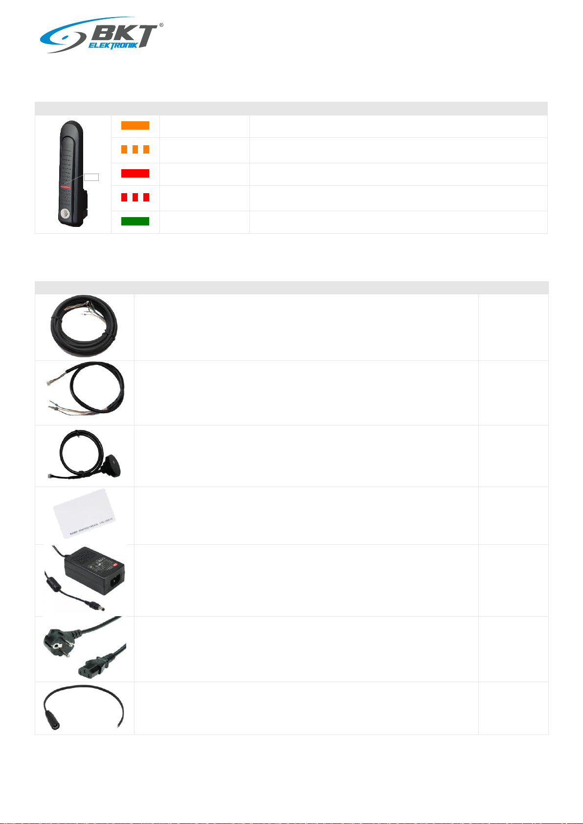
6Accessories
Product
Description
Part number
AW285 - AL200 swinghandle 8-wire connection cable, length 5m; connectors: 1-plug,
2-ferrules
122AW002850
AW240 - AL200 swinghandle 4-wire connection cable, length 0.5m; connectors: 1-plug,
2-ferrules
122AW002400
AR221 - AL200 swinghandle Unique 125kHz card reader (RS-H3-05-M12)
122AR002210
EMC-1 - UNIQUE EM 125 kHz thin proximity card
122AA101004
GST18A12-P1J - Power supply 18W 12VDC 1.5A; AC socket C14; DC plug 5.5/2.1; no AC cord
122AA100015
BKT AC power cord - socket IEC 320 C13 10A, plug DIN 49441(unischuko) 16A, 3 x 1,0 mm2
black 2m
11480784.2
Cable with DC 5.5/2.1 inlet; straight; 0.5mm2; black; 3m
122AA100016
LED

www.bkte.pl
AL200 swinghandle manual
15
Electrical junction box 86mm x 86mm x 39mm, wall mount, black, IP55
122AA100006
7Document revisions
Version
Changes
Date
1
Initial version.
March 2021
2
Updated 3.2, 3.3 and 3.4
July 2021
3
Support for rfid readers has been added for handles manufactured from 2Q2022. The device
manufacturing date can be checked on the sticker.
February 2022
Other manuals for AL200
1
Table of contents
Other BKT Elektronik Lock manuals


Popular Lock manuals by other brands


Alarm Lock
Alarm Lock PM1200 Wiring instruction

Kaba
Kaba 7102 series installation instructions

COMPX
COMPX C8142 Dimensional drawing

Sargent and Greenleaf
Sargent and Greenleaf 6128 A Series installation instructions

Corbin Russwin
Corbin Russwin Access 800 installation instructions

Salsbury Industries
Salsbury Industries 3596 installation instructions


