manuals.online logo
Brands
  1. Home
  2. •
  3. Brands
  4. •
  5. TownSteel
  6. •
  7. Lock
  8. •
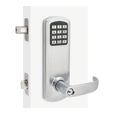
  9. TownSteel e-Genius 2000 Series User manual

TownSteel e-Genius 2000 Series User manual

TownSteel
e-Genius 2000 Series
Lock Installation
5 1/2” Center To Center
Table Of Contents
Package Content
Getting Started
Handing Information
Door Preparation
Step 1 - Adjust Latch Bolt
Step 2 - Set Handing On Latch Bolt
Step 3 -
Step 3 - Adjust Deadbolt
Step 4 - Install Deadbolt And Latch Bolt
Step 5 - Install Outside Lever
Step 6 - Install Outside Assembly
Step 7 - Install Backplate
Step 8 - Install Spindle And Connect Battery Tray
Step 9 - Set Handing On Battery Tray
Step 10 - Install Batteries
Step 11 - Install Escutcheon And Inside Lever
Step 12 - Install Strikes
Addendum A - Change Handing Information
Addendum B - Remove Levers
Addendum C - Change Handing On Outside Assembly
Exploded View Of Lock
T
Troubleshoot
1
2
4
5
6
7
8
9
9
10
11
12
13
14
15
16
16
17
18
19
20
21
22
23
23
YW1930
Package Content
2
Backplate
Outside Lever
Outside Assembly Battery Tray
Assembly
Inside Cover
Lever Removal
Tool
Thumb Turn
Spindle
Inside Lever Cylinder Retainer & Cylinder Latch BoltDEADBOLT
YW1930
Package Content
Screw Pack For Lock Assembly
Screw Pack For Faceplate
and Strike Installation
Latch Bolt Strike Deadbolt
Faceplate
Deadbolt
Armor Strike
Deadbolt Strike
3
YW1930
Getting Started
4
YW1930
This is an interconnect lock. Inside is always unlocked. Deadbolt can be extended from inside or outside by
lifting lever or using thumbturn on the inside. From inside, rotating lever down will retract both bolts. From
the outside, presenting a valid user code and rotating the lever down will retract both bolts.
Key Override
Rotating the key clockwise, approximately 90o-120o, will allow you to rotate the lever and retract both bolts.
The key will not retract the bolts. Return key back to home position to pull out key.
Tools Needed For Lock Installation
Phillips screw driver
Flat Head screw driver
Note:
Do not use a power drill for installation of lock as it can damage lock.
Tools May Be Needed For Door Preparation
Tape Measure
Power Drill (For drilling holes ONLY)
1" and 2 1/8" Drill Bits
Wood Chisel
Pencil
7/64 Hex Wrench
When batteries are installed and lock is ready to be operated, refer to programming guide for programming
instructions.
Handing Information
Interconnect lock is handed. See handing information below.
Handing Information From Outside
If handing needs to be changed, see Addendum A (Page 19).
5
If hinges are on the left,
and door opens inward,
it is a Left Hand Door(LH).
If hinges are on the left,
and door opens outward,
it is a Left Hand Reverse Door(LHR).
If hinges are on the right,
and door opens inward,
it is a Right Hand Door(RH).
If hinges are on the right,
and door opens outward,
it is a Right Hand Reverse Door(RHR).
YW1930
Door Preparation
Prepare door and jamb per template provided. Backset is adjustable for 2 ³⁄” or 2 ³⁄”. The
backset is the dimension from the edge of the door to centerline of the lock. This lock
requires a 5 ¹⁄” center to center distance between the bore holes.
IMPORTANT:
Door stop is where the door
will stop when normally
operated. Door stop includes
any gasket, smoke seal, or
bumpers. Position of strikes
are to be measured from
where the door actually stops.
The deadbolt, when thrown,
cannot have any interference
with the deadbolt strike. If
there is any interference,
strikes need to be adjusted for
lock to work properly.
6
Backset
5 1/2”
Door Stop
Door Jamb
Bore holes
YW1930
Step 1
Adjust latch bolt by adjusting hub.
7
To adjust from 2 3/8” to 2 3/4”, rotate hub on the diagonal as shown below. Pull hub to the
left. Push hub to the right to go back to 2 3/8”.
HUB
2 3/4”2 3/8”
YW1930
Step 2
After setting backset, the latch bolt needs to be handed for LH, RH, LHR, and RHR doors.
Rotate hub as specified. 2 ³⁄” latch depicted below. For 2 ³⁄”, latch should remain extended
after rotation.
LH Latch RH Latch
LHR Latch RHR Latch
8
Note: Rotate hub counter clockwise
until latch matches image shown
Note: Rotate hub clockwise
until latch matches image shown
YW1930
Step 3
Place the deadbolt in the door frame cutout and make sure the cross shaped hub is centered.
Otherwise, look below on how to adjust the deadbolt by rotating the deadbolt face.
2³⁄” 2³⁄”
9
YW1930
Step 4
Extend deadbolt. Install deadbolt, deadbolt faceplate, and latch bolt as shown (RH Shown).
Secure with 4 screws.
Position cross as shown below.
10
Deadbolt
Deadbolt
Faceplate
Latch Bolt
YW1930
Step 5
Install Outside Lever
1) Insert key and rotate cylinder 90° clockwise(CW).
*Note: LH lever and RH lever orientation
2) Use a flat head screw driver to rotate slot in spindle 90° CW on
outside assembly.
3) With key inserted and rotated 90° CW, push lever onto outside
assembly while the slot is also rotated 90° CW. Lever catch is on
underside of lever and it should snap into place. Rotate keyway
back to home position and pull out key. Pull lever to make sure
lever is secure.
Slot Normal
Orientation
11
Slot Rotated 90° CW
For Lever Installation
Home
Position
Rotated
90° CW
LH OR LHRLH OR LHR
RH OR RHR RH OR RHR
Lever Catch
Slot In Lock
Spindle
Lever With Cylinder
and Cylinder Retainer
RH or RHR
Lever Orientation
Lock Spindle
YW1930
Step 5
Align outside lock assembly and install onto door face. Lever spindle goes through latch hub.
Carefully guide wire harness through and over deadbolt housing.
Outside Lock
Assembly
Lever Spindle
Wire
Harness
12
Route Wire Over Deadbolt
Note:
Do Not Pull on Wire Harness
YW1930
13
Note:
Do not pull on wire harness
Backplate
Align backplate and install on the door. Guide the wire harness above the shelf on backplate
and down through the slot. Secure top of backplate with 2 screws that go through the
deadbolt housing - do not tighten until all screws on the backplate are installed. Secure
bottom of backplate with 4 screws. Tighten all screws on backplate.
YW1930
14
Step 7
Install thumb turn spindle as shown. Plug in connector from lock assembly into connector
from battery tray.
Battery Tray
Connectors
Thumb Turn
Spindle
YW1930
Step 9
Set handing on battery tray. Push excess wire into hole over the backplate. Battery tray
should sit flush without interference. Do not pinch wire harness. Secure battery tray with 6
screws.
Set handing on battery tray as shown
below.
RH, RHRLH, LHR
15
Note: Confirm the deadbolt is extended and
thumb turn spindle is installed.
YW1930
Step 10
Install 4 AA-alkaline batteries into battery tray. Use only alkaline batteries for the interconnect
lock.
16
When batteries are
installed, you will
hear the motor move,
see the LED light up,
and hear a quick
series of beeps.
YW1930
Step 11
Place back cover over battery tray. Make sure the thumb turn on the back cover is oriented
properly. Align thumb turn until it falls into place without forcing it. Secure back cover with 2
screws. Slide inside lever onto lock spindle. Lever catch is on underside of lever and it
should snap into place. Pull lever to make sure it is secure.
Back Cover
Thumb Turn
Inside Lever
Lock Spindle
17
YW1930
Step 12
Install deadbolt armor plate, deadbolt strike, and latch bolt strike. Secure with 6 screws.
Latch Bolt
Strike
Deadbolt
Armor Plate
Deadbolt
Strike
Door
Stop Remember, the door stop is where
the door will stop when normally
operated. Stop includes any gasket,
smoke seal, or bumpers. Position of
strikes are to be measured from
where the door actually stops. The
deadbolt, when thrown, cannot have
any interference with deadbolt strike.
If there is any interference, strikes
need to be adjusted for the lock to
work properly.
18
IMPORTANT:
Make sure the lock operates properly before closing the door. From inside, lifting the lever should
extend the deadbolt and rotating the lever down should retract both bolts. From outside, lifting the
lever should extend the deadbolt. Enter 1-2-3-4-5. The LED will light green. Rotating the lever down
should retract both bolts. Key override, rotating the key unlocks the lock momentarily to allowing the
lever to retract both bolts. When key is removed, the lock will return to being locked.
YW1930
IMPORTANT:
Make sure the lock operates properly before closing the door. From inside, lifting the lever should
extend the deadbolt and rotating the lever down should retract both bolts. From outside, lifting the
lever should extend the deadbolt. Press the following keys on the keypad to check proper function, enter
1-2-3-4-5. The LED will light red then green. Rotating the lever down should retract both bolts.
allowing the lever to retract both bolts.Key override, rotating the key unlocks the lock momentarily
When key is removed, the lock will return to being locked.
Addendum A
Changing the handing should not be needed. Lock is shipped with handing specified. See
shipping confirmation or box for details.
If handing needs to be changed from Right Hand to Left Hand (Or Left Hand to Right Hand),
handing must be changed on outside assembly. This entails changing a socket head screw
on the back of outside assembly. Also, latch bolt and levers need to be adjusted.
See:
Addendum C To change handing on outside assembly
Addendum B To remove and adjust levers
Step 2 To adjust latch bolt
If handing needs to be changed from Right Hand to Right Hand Reverse (Or Left Hand to
Left Hand Reverse), only the latch bolt orientation needs to be changed.
See:
Step 2 In order to adjust latch bolt
19
YW1930

Other TownSteel Lock manuals

TownSteel e-Smart 6000 Series User manual

TownSteel

TownSteel e-Smart 6000 Series User manual

TownSteel E-GENIUS 2000 Series User manual

TownSteel

TownSteel E-GENIUS 2000 Series User manual

TownSteel 2000 Series Troubleshooting guide

TownSteel

TownSteel 2000 Series Troubleshooting guide

TownSteel e-lite 4000 Series Operating instructions

TownSteel

TownSteel e-lite 4000 Series Operating instructions

TownSteel e-Elite 4000 Series Operating instructions

TownSteel

TownSteel e-Elite 4000 Series Operating instructions

TownSteel e-Genius 2990 Series Operating instructions

TownSteel

TownSteel e-Genius 2990 Series Operating instructions

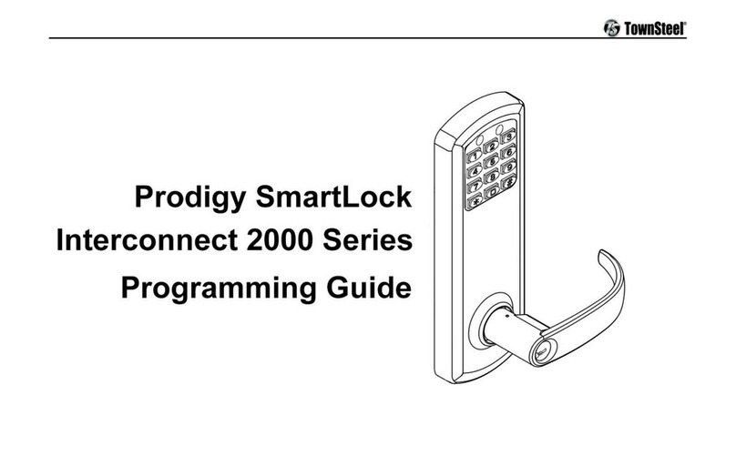
TownSteel Prodigy SmartLock Interconnect 2000 Series Operating instructions

TownSteel

TownSteel Prodigy SmartLock Interconnect 2000 Series Operating instructions

TownSteel Prodigy SmartLock 4000 Series Troubleshooting guide

TownSteel

TownSteel Prodigy SmartLock 4000 Series Troubleshooting guide

TownSteel XCE 2000 Series User manual

TownSteel

TownSteel XCE 2000 Series User manual

TownSteel MDE Series User manual

TownSteel

TownSteel MDE Series User manual
Popular Lock manuals by other brands

TESA GLOBAL 1E Series Assembly instructions

TESA

TESA GLOBAL 1E Series Assembly instructions

Kramer KT-107-OWLK quick start guide

Kramer

Kramer KT-107-OWLK quick start guide

Safety 1st OUTSMART 3202007000 instructions

Safety 1st

Safety 1st OUTSMART 3202007000 instructions

Bruker DAEDALUS Service manual

Bruker

Bruker DAEDALUS Service manual

Securam ProLogic B22 Operation instructions

Securam

Securam ProLogic B22 Operation instructions

Ergotron StyleView 97-702 Assembly instructions

Ergotron

Ergotron StyleView 97-702 Assembly instructions

COMPX C8070 Dimensional drawing

COMPX

COMPX C8070 Dimensional drawing

Apco IMSystem General instructions

Apco

Apco IMSystem General instructions

jokab safety Dalton Original instructions

jokab safety

jokab safety Dalton Original instructions

Assa Abloy Lockwood 3P82TSS-A11E Mounting instructions

Assa Abloy

Assa Abloy Lockwood 3P82TSS-A11E Mounting instructions

Kaadas L8 user manual

Kaadas

Kaadas L8 user manual

CENTURION SYSTEMS D5-EVO Configuration guide

CENTURION SYSTEMS

CENTURION SYSTEMS D5-EVO Configuration guide

National Cabinet Lock C8402 Dimensional drawing

National Cabinet Lock

National Cabinet Lock C8402 Dimensional drawing

Rivers Locking Systems D quick guide

Rivers Locking Systems

Rivers Locking Systems D quick guide

Salto Ei75 Series installation guide

Salto

Salto Ei75 Series installation guide

Ingersoll-Rand Schlage e.PRIMUS Le Series Upgrade instructions

Ingersoll-Rand

Ingersoll-Rand Schlage e.PRIMUS Le Series Upgrade instructions

YEEUU S1 Smart Lock quick start guide

YEEUU

YEEUU S1 Smart Lock quick start guide

Yale GATEMAN YDM 3109 user manual

Yale

Yale GATEMAN YDM 3109 user manual

manuals.online logo
manuals.online logoBrands
  • About & Mission
  • Contact us
  • Privacy Policy
  • Terms and Conditions

Copyright 2025 Manuals.Online. All Rights Reserved.