Black Box CityLIGHT LCL533A User manual

CityLIGHT® 10/100 Ethernet
Transceiver Card
FEBRUARY 2001
LCL533A
LCL534A
LCL535A
LCL536A
Order toll-freeintheU.S. 24hours, 7 A.M.Monday tomidnightFriday:877-877-BBOX
FREE technical support, 24 hours a day, 7 days a week: Call724-746-5500 or fax 724-746-0746
Mail order: Black Box Corporation, 1000Park Drive, Lawrence, PA15055-1018
Website:http://www.blackbox.com E-mail:info@blackbox.com
CUSTOMER
SUPPORT
INFORMATION

CITYLIGHT 10/100 ETHERNET TRANSCEIVER CARD
2
FEDERAL COMMUNICATIONS COMMISSION
AND
CANADIAN DEPARTMENT OF COMMUNICATIONS
RADIO FREQUENCY INTERFERENCE STATEMENTS
This equipment generates, uses, and can radiate radio frequency energy and if not
installed and used properly, that is, in strict accordance with the manufacturer’s
instructions, may cause interference to radio communication. It has been tested and
found to comply with the limits for a Class A computing device in accordance with the
specifications in Subpart J of Part 15 of FCC rules, which are designed to provide
reasonable protection against such interferencewhen the equipment is operated in a
commercial environment. Operationofthis equipment in a residentialarea is likely to
cause interference, in which case the user at his own expense will be required to take
whatever measures may be necessary to correct the interference.
Changes or modifications not expressly approved by the party responsible for
compliancecouldvoidthe user’s authority tooperate the equipment.
This digital apparatus does not exceed the Class A limits for radio noise emission from
digital apparatus set out in the Radio Interference Regulation of the Canadian
Department of Communications.
Le présent appareil numérique n÷émet pas de bruits radioélectriques dépassant les
limites applicables aux appareils numériques de la classe A prescrites dans le
Règlement sur le brouillage radioélectrique publié par le ministère des
Communications du Canada.

CITYLIGHT 10/100 ETHERNET TRANSCEIVER CARD
3
NORMAS OFICIALES MEXICANAS (NOM)
ELECTRICALSAFETY STATEMENT
INSTRUCCIONES DE SEGURIDAD
1. Todas las instrucciones de seguridad y operación deberán ser leídas antes de
que el aparato eléctrico sea operado.
2. Las instrucciones de seguridad y operación deberán ser guardadas para
referenciafutura.
3. Todas las advertencias en el aparato eléctrico y en sus instrucciones de
operación deben serrespetadas.
4. Todas las instrucciones de operacióny uso deben serseguidas.
5. El aparato eléctrico no deberá ser usado cerca del agua—por ejemplo, cerca
de latinade baño, lavabo, sótano mojado o cerca de unaalberca, etc.
6. El aparato eléctrico debe ser usado únicamente con carritos o pedestales que
sean recomendados por el fabricante.
7. El aparato eléctrico debe ser montado a la pared o al techo sólo como sea
recomendado porel fabricante.
8. Servicio—El usuario no debe intentar dar servicio al equipoeléctrico más allá a
lo descrito en las instrucciones de operación. Todo otro servicio deberá ser
referido a personal de servicio calificado.
9. El aparato eléctrico debe ser situado de tal manera que su posición no interfiera
su uso. La colocación del aparato eléctrico sobre una cama, sofá, alfombra o
superficie similar puede bloquea laventilación, no se debe colocar enlibreros o
gabinetes que impidan elflujo deaire por los orificios de ventilación.
10. El equipo eléctrico deber ser situado fuera del alcance de fuentes de calor
como radiadores, registros de calor, estufas u otros aparatos (incluyendo
amplificadores) que producen calor.

CITYLIGHT 10/100 ETHERNET TRANSCEIVER CARD
4
11. El aparato eléctrico deberá ser connectado a una fuente de poder sólo del tipo
descrito en el instructivo deoperación, o comose indiqueenel aparato.
12. Precaución debe ser tomada de tal manera que la tierra fisica y la polarización
delequipo no sea eliminada.
13. Los cablesde lafuente de poder deben ser guiados detal manera queno sean
pisados ni pellizcados por objetos colocados sobre o contra ellos, poniendo
particular atención a los contactos y receptáculosdonde salendel aparato.
14. El equipo eléctrico debe ser limpiado únicamente de acuerdo a las
recomendaciones del fabricante.
15. En caso de existir, unaantenaexterna deberá ser localizada lejos de las lineas
deenergia.
16. El cable de corriente deberá ser desconectado del cuando el equipo no sea
usado por unlargo periodo detiempo.
17. Cuidado debe ser tomado de tal manera que objectos liquidos no sean
derramados sobre la cubierta u orificios de ventilación.
18. Serviciopor personal calificado deberá ser provisto cuando:
A: El cable depoder oel contacto ha sidodañado; u
B: Objectos han caído olíquido ha sido derramado dentro delaparato; o
C: El aparato ha sidoexpuesto a lalluvia; o
D: El aparato parece no operar normalmente o muestra un cambio en su
desempeño; o
E: El aparato ha sido tirado o su cubierta hasido dañada.

CITYLIGHT 10/100 ETHERNET TRANSCEIVER CARD
5
CERTIFICATIONNOTICE FOR
EQUIPMENT USEDIN CANADA
The Canadian Department of Communications label identifies certified equipment.
This certification means that the equipment meets certain telecommunications-
network protective, operation, and safety requirements. The Department does not
guarantee the equipment willoperate to theuser’s satisfaction.
Before installing this equipment, users should ensure that it is permissible to be
connected to the facilities of the local telecommunications company. The equipment
must alsobe installedusing an acceptable method of connection. In some cases, the
company’s inside wiring associated with a single-line individual service may be
extended by means of acertified connector assembly (extension cord). The customer
should be aware that compliance with the above conditions may not prevent
degradation of service in some situations.
Repairs to certified equipment should be made by an authorized Canadian
maintenance facility—in this case, your supplier. Any repairs or alterations made by
the user to this equipment, or equipment malfunctions, may give the
telecommunications company cause to request the user to disconnect the
equipment.
Users should ensure for theirown protection that the electrical ground connections of
the power utility, telephone lines, and internal metallic water pipe system, if present,
are connected together. This precaution may be particularly importantinrural areas.
CAUTION:
Users should not attempt to make such connections themselves,
but should contact the appropriate electric inspection authority, or
electrician, as appropriate.
The LOAD NUMBER (LN) assigned to each terminal device denotes the percentage
of the total load to be connected to a telephone loop which is used by the device, to
prevent overloading. The termination on a loop may consist of any combination of
devices, subject only to the requirement that the total of the load numbers of all the
devices does not exceed 100.

CITYLIGHT 10/100 ETHERNET TRANSCEIVER CARD
6
CONTENTS
Chapter Page
CONTENTS................................................................................... 6
1. SPECIFICATIONS ................................................................... 7
2. PRODUCT OVERVIEW .......................................................... 9
2.1 Auto-negotiation ........................................................................................ 9
2.2DataRate ................................................................................................ 12
2.3Frame Size .............................................................................................. 12
2.4DriveDistance ......................................................................................... 12
2.5 External Attenuator .................................................................................. 12
2.6 Ergonomics ............................................................................................. 13
2.7 Power Supply .......................................................................................... 13
2.8 Link Loss Forwarding ............................................................................... 13
2.9 Management ........................................................................................... 14
2.9.1Temperature ..................................................................................... 14
2.9.2 Laser Bias Current ............................................................................. 15
2.9.3 Link Activity ....................................................................................... 15
2.9.4RemoteFault..................................................................................... 15
2.9.5 Copper and Fiber Port Status.............................................................. 15
2.9.6 Other Managed Features ................................................................... 16
2.10ShippingContents.................................................................................. 16
3. INSTALLATION .................................................................... 17
3.1 Tools Required ........................................................................................ 17
3.2BeforeYouStart....................................................................................... 17
3.3 General Set-Up........................................................................................ 17
4. DIAGNOSTIC LEDs............................................................... 21
5. SWITCH POSITIONS ............................................................ 23
APPENDIX A - TROUBLESHOOTING ................................... 26
APPENDIX B - GLOSSARY OF TERMS................................. 29
Figures
Figure 1 - CityLIGHT 10/100 Ethernet Transceiver ................................................ 9
Figure2 - Typical Application.............................................................................. 11
Figure 3 - Switch Positions ................................................................................. 23

CITYLIGHT 10/100 ETHERNET TRANSCEIVER CARD
7
1. SPECIFICATIONS
DATA RATE 10 OR 100Mbps
OPTICALPOWERBUDGET 18dBSTANDARDPOWER
25 dB HIGH POWER
TYPICALLAUNCH -11.5dBmSTANDARD POWER
-1.5dBmHIGH POWER
MINLAUNCH POWER -13dBmSTANDARD POWER
-3dBmHIGH POWER
MIN RECEIVE POWER -28 dBm
LINK LENGTHS
OPTICAL 9/125µmFIBER UP TO 50 km; 31.3 MILES (25 dB)
UP TO 35 km; 22.5 MILES (18 dB)
ELECTRICAL TYPE 3(CAT 5 UTP) RJ
45(24AWG)
UP TO 100M
CONNECTORPINOUTSRJ 45
TX+ 1
TX- 2
RX+ 3
RX- 6
CONNECTORS
OPTICAL SC/ST(ORDER TIMEOPTIONS)
ELECTRICAL SHIELDEDRJ45

CITYLIGHT 10/100 ETHERNET TRANSCEIVER CARD
8
ENVIRONMENTAL
TEMPERATURE OPERATING: 32TO 104°F (0TO 40°C);
STORAGE: 14TO 158°F(-10 TO +70°C)
HUMIDITY MAX95%(NON-CONDENSING)
STANDARDS SUPPORTED IEEE802.3AND IEEE 802.3U
WEIGHT 0.15 kg; 0.33 lb.
ELECTRICALINFORMATION
MAX.CURRENT LESS THAN 1.5A@5V
POWERCONSUMPTION LESSTHAN 7.5W
COMPLIANCE UL1950
CUL1950
CE 73/23/EEC
CE 89/336/EEC
CARDVARIANTS
LCL533A
LCL534A
LCL535A
LCL536A
10/100 ETHERNET, RJ 45 TO SMSC, 35KM
10/100 ETHERNET, RJ 45 TO SMSC, 50KM
10/100 ETHERNET, RJ 45 TO SMST, 35KM
10/100 ETHERNET, RJ 45 TO SMST, 50KM

CITYLIGHT 10/100 ETHERNET TRANSCEIVER CARD
9
2. PRODUCT OVERVIEW
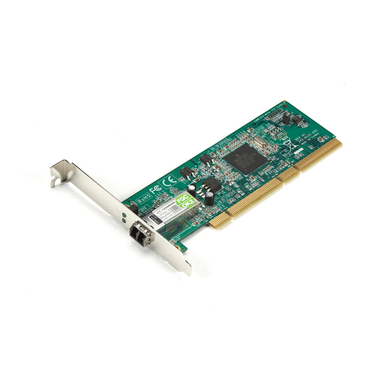
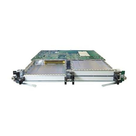
The CityLIGHT 10/100 Ethernet Transceiver is part of the CityLIGHT system and
is designed to provide both 10BASE-T and 100BASE-TXLANinterfaces.
It retransmits data between the connected devices over distances of up to 35 km
on single-mode fiber using standard optics orup to 50 km using high-power optics.
The CityLIGHT 10/100 Ethernet Transceiver reduces received jitter which
ensures error-free operation when connected to any IEEE 802.3device.
Figure 1 - CityLIGHT 10/100 Ethernet Transceiver
2.1 Auto-negotiation
The CityLIGHT 10/100 Ethernet Transceiver supports auto-negotiation on the
copper/user port. When enabled the port will advertise its capabilities to the
attached port and negotiateto thehighest common mode.
Modes are 100BASE-TX FDX
100BASE-TX HDX
10BASE-T FDX
10BASE-T HDX

CITYLIGHT 10/100 ETHERNET TRANSCEIVER CARD
10
NOTE: The CityLIGHT 10/100 is a transceiver. The devices attached to the
CityLIGHT 10/100 Ethernet Transceiver at either end MUST have the
same highest common capability and operate in the same mode and
speed, e.g. all elements of the link must be operating at say 10 Mbps
Full-Duplex or all at 100 Mbps Full-Duplex. It is not possible to mix
Half- and Full-Duplex operation or 10 Mbps and 100 Mbps operation
onthe same link.
NOTE: The CityLIGHT 10/100 Ethernet Transceiver will advertise all these
capabilities and operates transparently in Half- or Full-Duplex mode.
However care must be taken when the local port operates in Half-
Duplex mode as distance is limited by the Half-Duplex Ethernet
protocol. In Full-Duplex Mode the Ethernet Protocol does not limit
distance.

CITYLIGHT 10/100 ETHERNET TRANSCEIVER CARD
11
Token
CuIns
RXAl
Data
Bcn
4/16
TokenRing
Rem.F.
Pwr1
Pwr2
CityLIGHT
Single-mode
fiber link
up to 50 km
Crossover Cable
Crossover Cable
PC running SNMPc
Crossover cable
Token
CuIns
RXAl
Data
Bcn
4/16
TokenRing
Rem.F.
CityLIGHT SNMP Card CityLIGHT 10/100
Ethernet Transceiver Card
CityLIGHT 10/100 Ethernet Transceiver
Card
Switch with Auto-negotiation port
capable of running 10 or 100 Mbps
A typical application interconnecting
two sites over a long fiber link.
The CityLIGHT Sideband
management provides monitoring of
both the 10/100 cards on the link.
The default settings of the
CityLIGHT 10/100 Ethernet
Transceiver Card permit auto-
negotiation at each end.
This automatically allows
connections to 10 Mbps and 100
Mbps systems in Half- or Full-Duplex
mode.
The inter-switch link is always up to
36 km for standard power devices
and up to 50 km for high power.
Switch with Auto-negotiation port
capable of running 10 or 100 Mbps
Figure 2 - Typical Application
The example above shows the simplest CityLIGHT configuration. The CityLIGHT
10/100 Ethernet Transceiver can be used in any of the CityLIGHT chassis
including the 3UChassis which canmanage up to 32devices from 1 SNMP agent.

CITYLIGHT 10/100 ETHERNET TRANSCEIVER CARD
12
Auto-negotiation is enabled by setting switch 2 to ON; see Section 5, Switch
Positions. Setting switch 2 OFF allows the data rate to be controlled by the
speed select switch (Switch 1); see Section 5, Switch Positions.
2.2 Data Rate
The CityLIGHT Fiber Extender Modules can operate at either 10 or 100 Mbps.
Switch 1 controls the speed whenever auto-negotiation is not enabled; see
Section 5, Switch Positions:
ON –100Mbps.
OFF – 10Mbps.
The CityLIGHT 10/100 Ethernet Transceiver works transparently with either full-
or half-duplex ports attached, though users shouldbe aware distance is limited by
the Ethernet protocol in half-duplex environments.
2.3 Frame Size
The CityLIGHT 10/100 Ethernet Transceiver transparently supports all frame
sizes including longer frames used for VLAN tagging. This includes transmission
of 802.1q VLAN tagged frames as well as ISL 1548 bytelength frames.
2.4 Drive Distance
The CityLIGHT 10/100 Ethernet Transceiver allows a user to connect LAN
interfaces over extended distances. Each copper port has a maximum drive
distanceof 100 mon UTP cables. Every CityLIGHT 10/100 Ethernet Transceiver
fiber link can be up to 35 km using standard optics or 50 km using high-power
optics. Two launch-power options are available; a standard-power unit typically
launching at -10 dBm and a high-power unit at -3 dBm. All units receive to a
minimum light levelof -28 dBm. See Specifications for more details.
2.5 External Attenuator
All high-power or long haulCityLIGHT cards have been designed for longdistance
transmission and provide a minimum optical budget ranging between 20dB and
25dB. This provides transmission distances between 40km and 50km based on
anaverage fiberattenuationof 0.5dB/km.
When these products are used for short distance applications, the received
power may exceed the saturation limit of the receiver and external
attenuation will be necessary to prevent optical overload and the inevitable
data errors.

CITYLIGHT 10/100 ETHERNET TRANSCEIVER CARD
13
For these applications, an external 10dB attenuator is available to ensure that
the optical receive power falls within the operating limits of the receiver.
The fixed value 10dB attenuator, LCL505A, is of a doped-fiber design which
eliminates the troublesome reflections which anair-gap attenuator may introduce.
These reflections can upset the operation of lasers, particularly those used in high
dataratesystems.
The 10dB attenuator may bedeployed anywhere in thesingle-mode fiber link but it
is recommended that it be deployed at the receive end (rather than the transmit
end) of any particular point-to-point link.
The attenuator has a female connector at one end and a male connector at the
other end. The connector style shouldbespecifiedat thetime of ordering.
2.6 Ergonomics
The CityLIGHT 10/100 Ethernet Transceiver is able to be installed in any of the
CityLIGHT chassis including the 1U Chassis and 2-Card Chassis as well as the 3U
Chassis.
2.7 Power Supply
The CityLIGHT 10/100 Ethernet Transceiver receives all its power from the PSUs
mounted inthe CityLIGHT Chassis. All chassis can support ACand 48V DC PSUs
in single and redundant forms. (See the CityLIGHT 1U or 3U Chassis or
CityLIGHT 2-Card Chassis as applicable for details).
2.8 Link Loss Forwarding
To allow fiber link failures to be passed to the copper interface, a link loss
forwarding feature is provided.
This is enabled by setting switch 4 to ON, and is disabled when switch 4 is OFF; see
Section 5, Switch Positions.
When enabled failures on the fiber link are passed to the copper port; they can be
seen by the device attached to the copper port as a link failure. Consequently the
fiber link must be good before thecopper link is established.
When disabled, each of the fiber and copper links are established independently.

CITYLIGHT 10/100 ETHERNET TRANSCEIVER CARD
14
2.9 Management
The CityLIGHT 10/100 Ethernet Transceiver is managed via the CityLIGHT
SNMP Module which supports both In-Band and Out-of-Band management ofthe
unit.
Once installed in a chassis with an SNMP card or connected via the fiber to a card
in an SNMP-managed chassis, the SNMP agent automatically detects the card
and displays the followinginformation.
NOTE: This information is the same for the local and remote cards and is
availablevia the terminalinterface as well as the SNMP MIB.
i) Card Type
ii) Card Speed
iii) Fiber Port Link Status
iv) Copper Port Link Status
v) Temperature
vi) Fan Status
vii) Laser Bias Current
viii) PSU Voltage
ix) Redundant PSU State
x) Serial Number
xi) Firmware Version Number
xii) Location (entered by theuser, seeSNMP cardmanual for details)
The CityLIGHT SNMP Module provides trap alarms for the following parameters
of the CityLIGHT Fiber Extender Module.
2.9.1 Temperature
This is the temperature of the CityLIGHT Fiber Extender Module. A trap alarm is
generated if the temperature is not within the required range.

CITYLIGHT 10/100 ETHERNET TRANSCEIVER CARD
15
2.9.2 Laser Bias Current
The laser bias current gives an indication of the drive current required to maintain
the correct output power of the laser on the CityLIGHT Fiber Extender Module.
The value of the laser bias is used to generate a trap if a threshold value is
exceeded. This indicates that the laser is approaching its end of life and the card
should be replaced during a suitable maintenance window.
2.9.3 Link Activity
This gives an indication ofdata activity on the copperconnectionof the CityLIGHT
Fiber Extender Module. Its state is either active (carrying LAN data) or inactive
(not carrying LANdata).
2.9.4 Remote Fault
The local 10/100 Ethernet Transceiver indicates that a fault has occurred on the
remote Fiber Extender Module. The copper and fiber port status can be used to
determine the exact problem.
2.9.5 Copper and Fiber Port Status
Thesegive anindicationof thestate ofboth the copper and fiberconnections tothe
CityLIGHT Fiber Extender Module.
The fiber port may indicate:
i. Inserted (the CityLIGHT 10/100 Ethernet Transceiver is correctly
attached).
ii. Rx Alarm (the CityLIGHT 10/100 Ethernet Transceiver is not
receivinglight from the far end device. A fault lies in the farend device
or the receive fiber path).
iii. CheckTx (the port is inactive. The CityLIGHT 10/100 Ethernet
Transceiver in the CityLIGHT managed chassis has been
recognized on the receive fiber but a faultlies inthe pathbetween this
CityLIGHT 10/100 Ethernet Transceiver and the remote unit’s
receiver).
The copper port may indicate:
iv. Active (this CityLIGHT 10/100 Ethernet Transceiver is receiving link
pulses on the copper interface and is therefore correctly attached
and all other ports,both local and remote, are good).

CITYLIGHT 10/100 ETHERNET TRANSCEIVER CARD
16
v. Link UP (this CityLIGHT 10/100 Ethernet Transceiver is receiving
link pulses on the copper interface but thecopper port at the far end is
reportinga fault).
vi. Link DOWN (this CityLIGHT 10/100 Ethernet Transceiver is not
receiving link pulses on the copper interface and is therefore not
correctly attached).
2.9.6 Other Managed Features
The CityLIGHT SNMP Module also monitors the PSUs and cooling fans of both
the CityLIGHT 1U or 3U Chassis and CityLIGHT 2-Card Chassis. Refer to the
user manual supplied with the CityLIGHT SNMP Module for more details.
2.10 Shipping Contents
The shippingcarton contains:
This manual (1)
CityLIGHT 10/100 Ethernet Transceiver(1)
Ethernet crossover cable (1)

CITYLIGHT 10/100 ETHERNET TRANSCEIVER CARD
17
3. INSTALLATION
NOTE: The CityLIGHT 10/100 Ethernet Transceiver is hot-swappable; the
power to the CityLIGHT 1U or 3U Chassis and the CityLIGHT 2-Card
Chassis does not need to be turnedoff during installation orremoval.
3.1 Tools Required
To install the CityLIGHT Fiber Extender Module, the following items are required:
Flat-bladed Screwdriver
Fiber Cleaning Kit
Fiber Patch Cords
Electrical Patch Cables
Loss Set (Power Meter and 1300 nm Light Source)
3.2 Before You Start
Make sure that both CityLIGHT chassis (local and remote) are correctly installed.
Make sureyou havethe followinginformationbefore youstart:
Cable Type: 100ΩCategory 5 RJ 45.
Fiber Connection: Check that the connections on the units, the patch cords used,
and thesite requirement are compatible.
As the CityLIGHT 10/100 Ethernet Transceiver is a long-distance product,
installation is greatly simplified with a technician at each end of the link. This
allows link tests to be completed in the minimum of time.
3.3 General Set-Up
1) Set switch 1to therequiredoperating speed; OFF for 10 Mbps or ON for
100 Mbps operation on both CityLIGHTFiber Extender Modules.

CITYLIGHT 10/100 ETHERNET TRANSCEIVER CARD
18
2) Configure theattached switches to fixed-rate full-duplex for therequired
speed. If the attached switches/ports only support “auto” mode, the
CityLIGHT 10/100 Ethernet Transceiver can auto-negotiate with these
ports to allow full-duplex operation. Setting switch 2 ON enables auto-
negotiation. With switch 2set to ON, switch 1 has no effect.
NOTE: Auto-negotiation does not take place across the fiber link. The local
user/copper ports negotiate independently. Consequently the ports at
both ends of thelink must support the same highest commonmode. i.e.
one end must not negotiate a 100 Mbps link if the far end can only
negotiate a10 Mbps link.
3) If an SNMP card is present in either of the chassis on the link, both
Local/Remote switches should be set to Remote i.e. both cards must
have switch 3 ON (this is the default setting).
NOTE: If no SNMP card is present in either of the chassis, one card MUST be
set to Local andthe other toRemote, (setting thecard toLocal allows the
link connection to operate correctly; when present, the SNMP card
controls this automatically). With no SNMP card in either chassis, one
card must haveswitch 3 set to OFF (Local) and the other far-end device
set to ON (Remote).
4) If link loss forwarding is required, set switch 4 to ON. (In this mode
failures on the fiber link cause the copper(user) link to be dropped).
If the state of the fiber link is not to affect the copper link then switch 4
must be set to OFF. In this mode each of the fiber and copper links
establish themselves independently. This is the default setting.
5) Positionthe first CityLIGHT 10/100 Ethernet Transceiver at therequired
slot in theCityLIGHT management chassis.
6) Push the CityLIGHT 10/100 Ethernet Transceiver along the card guides
into the slot until it engages with the connector inside the CityLIGHT
chassis. Repeatat theremote location.
7) Tighten the two captive screws on the front panels of both CityLIGHT
10/100 Ethernet Transceivers to secure them in position.
8) Make sure on both CityLIGHT 10/100 Ethernet Transceivers that the
100 LED illuminates to indicate that power is available and that it is the
correct color, (yellow for 10 Mbps or green for 100 Mbps). Also note that
the Alarm LED illuminates.

CITYLIGHT 10/100 ETHERNET TRANSCEIVER CARD
19
9) Using the loss set, and ideally a technician at the CityLIGHT remote
chassis, check that the link budget is less than 18 dB for the standard-
power unit or25 dB for the high-powerunit.
10) Ensure connector ends are clean. Connect the fiber cables to theRx and
Tx connectors at both ends of thelink. Make sure that thelocal transmit
is connected tothefar end receive and vice versa.
11) Make sure the Alarm LED is extinguished. If the Alarm LED on the
CityLIGHT 10/100 Ethernet Transceiver in the CityLIGHT managed
chassis remains illuminated, check that the receive power is greater
than -28 dBm. If it is less than -28 dBm, check the launch power of the
CityLIGHT 10/100 Ethernet Transceiver in the CityLIGHT remote
chassis and check the fiber connections are correctly made Tx to Rx.
12) If the Alarm LED on the CityLIGHT 10/100 Ethernet Transceiver in the
remote chassis remains illuminated, check that the receive power is
greater than -28 dBm. If it is less than -28 dBm, check the launch power
of the CityLIGHT 10/100 Ethernet Transceiver in the CityLIGHT
managed chassis.
13) At both CityLIGHT Fiber Extender Modules insert the copperinterface in
theRJ4510T/100TXport. Toconnect to a DCE, use a straight-through
cable; to connect to a DTE, use the crossover cablesupplied. Make sure
the Link LEDilluminates.
14) Once the link is correctly made, check the following:
i) The 100 LED is illuminated and is the correct color at both ends of
the link.
ii) The LinkLED is illuminated.
iii) The Rem F LED is extinguished.
iv) The Alarm LED is extinguished.
v) The DataLED flashes (if the link is active).
If any of the LEDs is not correctly illuminated/extinguished, see
Appendix A – Troubleshooting for possible causes.
NOTE: During commissioning most faults are associated with bad/wrong
cabling, incorrect patching, loss of power, or excessive powerbudget.

CITYLIGHT 10/100 ETHERNET TRANSCEIVER CARD
20
The hardware installation is now complete. To enable management, refer
to the Management Serial Interface section of the CityLIGHT SNMP
Module user manual.
This manual suits for next models
3
Table of contents
Other Black Box Network Card manuals

Black Box
Black Box DSL LAN Extender 400 User manual

Black Box
Black Box DSL LAN Extender 200 User manual

Black Box
Black Box LH3000 User manual

Black Box
Black Box LG9230CtX-32 User manual

Black Box
Black Box LCL931A User manual

Black Box
Black Box Channel Controller User manual

Black Box
Black Box LE7005A-UTP-R2 User manual

Black Box
Black Box LH1660C-SC User manual

Black Box
Black Box Ethernet PC Card User manual

Black Box
Black Box ME0001C-10BT User manual