Black Box DSL LAN Extender 400 User manual

DSL LAN Extender 400
OCTOBER 2002
LR0060A-
R3
Order toll
-
free in the U.S. 24 hours, 7 A.M. Monday to midnight Friday: 877
-
877
-
BBOX
FREE technical support, 24 hours a day, 7 days a week: Call 724-746-5500 or fax 724-746-0746
Mail order: Black Box Corporation, 1000 Park Drive, Lawrence, PA 15055-1018
FREE technical support, 24 hours a day, 7 days a week: Call 724
-
746
-
5500 or fax
724
-
746
-
0746
CUSTOMER
SUPPORT
INFORMATION

DSL LAN Extender 400 User’s Guide
© 2002 Black Box Corporation. Page i
FEDERAL COMMUNICATIONS COMMISSION and CANADIAN DEPARTMENT OF
COMMUNICATIONS RADIO FREQUENCY INTERFERENCE STATEMENT
Class B Digital Device. This equipment has been tested and found to comply with the limits for a
Class B computing device pursuant to Part 15 of the FCC Rules. These limits are designed to
provide reasonable protection against harmful interference in a residential installation. However,
there is no guarantee that interference will not occur in a particular installation. This equipment
generates, uses, and can radiate radio frequency energy, and, if not installed and used in
accordance with the instructions, may cause harmful interference to radio communications. If
this equipment does cause harmful interference to radio or telephone reception, which can be
determined by turning the equipment off and on, the user is encouraged to try to correct the
interference by one of the following measures:
•Reorient or relocate the receiving antenna.
•Increase the separation between the equipment and receiver.
•Connect the equipment into an outlet on a circuit different from that to which the receiver
is connected.
•Consult an experienced radio/TV technician for help.
Caution:
Changes or modifications not expressly approved by the party responsible for compliance
could void the user’s authority to operate the equipment.
To meet FCC requirements, shielded cables and power cords are required to connect this device
to a personal computer or other Class B certified device.
This digital apparatus does not exceed the Class B limits for radio noise emission from digital
apparatus set out in the Radio Interference Regulation of the Canadian Department of
Communications.
Le présent appareil numérique n’émet pas de bruits radioélectriques dépassant les limites
applicables aux appareils numériques de la classe B prescrites dans le Règlement sur le
brouillage radioélectrique publié par le ministère des Communications du Canada.
Normas Oficiales Mexicanas (NOM)
Electrical Safety Statement
INSTRUCCIONES DE SEGURIDAD
1. Todas las instrucciones de seguridad y operación deberán ser leídas antes de que el aparato
eléctrico sea operado.
2. Las instrucciones de seguridad y operación deberán ser guardadas para referencia futura.
3. Todas las advertencias en el aparato eléctrico y en sus instrucciones de operación deben ser
respetadas.
4. Todas las instrucciones de operación y uso deben ser seguidas.

DSL LAN Extender 400 User’s Guide
© 2002 Black Box Corporation. Page ii
5. El aparato eléctrico no deberá ser usado cerca del agua—por ejemplo, cerca de la tina de
baño, lavabo, sótano mojado o cerca de una alberca, etc.
6. El aparato eléctrico debe ser usado únicamente con carritos o pedestales que sean
recomendados por el fabricante.
7. Elaparato eléctrico debe ser montado a la pared o al techo sólo como sea recomendado por
el fabricante.
8. Servicio—El usuario no debe intentar dar servicio al equipo eléctrico más allá a lo descrito
en las instrucciones de operación. Todo otro servicio deberá ser referido a personal de
servicio calificado.
9. El aparato eléctrico debe ser situado de tal manera que su posición no interfiera su uso. La
colocación del aparato eléctrico sobre una cama, sofá, alfombra o superficie similar puede
bloquea la ventilación, no se debe colocar en libreros o gabinetes que impidan el flujo de
aire por los orificios de ventilación.
10. El equipo eléctrico deber ser situado fuera del alcance de fuentes de calor como radiadores,
registros de calor, estufas u otros aparatos (incluyendo amplificadores) que producen calor.
11. El aparato eléctrico deberá ser connectado a una fuente de poder sólo del tipo descrito en el
instructivo de operación, o como se indique en el aparato.
12. Precaución debe ser tomada de tal manera que la tierra fisica y la polarización del equipo
no sea eliminada. Normas Oficiales Mexicanas (NOM) Electrical Safety Statement.
Safety Precautions
Before attempting to set up or operate your DSL LAN Extender device, please read the following
precautions carefully.
1. Immediately upon unpacking the DSL LAN Extender device, inspect for external damage. If
the unit has been damaged in any way, do not attempt to operate it and contact Black Box
Corporation immediately. Do not connect the supplied power adapter to a power source if the
cord or the plug of the adapter is frayed or split.
2. Do not open the case. There are no user serviceable parts within.
3. Do not attempt to use any other similar power adapter other than the one supplied with the
package.
4. The supplied power adapter is designed exclusively for operation at 100V~240V, 47~63Hz
AC, unless otherwise specified. Before inserting the AC power plug into a wall socket, be
certain that your electrical power is within the correct range of values.
5. Do not operate the DSL LAN Extender device beyond the temperature and humidity range
specified (see specifications section).

DSL LAN Extender 400 User’s Guide
© 2002 Black Box Corporation. Page iii
6. Do not place near or over sources of heat such as a heater or radiator. Do not expose this unit
to rain or moisture.
7. Do not allow objects or foreign substances to enter the unit. If the unit malfunctions,
immediately turn off the power by removing the power plug from the outlet.
Note: Every effort has been made to make this user’s guide as complete and accurate as possible, but no
warranty or fitness is implied. The information is provided on an “as is” basis. Black Box Corporation
shall have neither liability nor responsibility to any person or entity, with respect to any loss or damage
arising from the information contained in this user’s guide or the use of the product itself.

DSL LAN Extender 400 User’s Guide
© 2002 Black Box Corporation. Page iv
Table of Contents
INTRODUCTION.........................................................................................................................................................................1
PRODUCT DESCRIPTION.......................................................................................................................................................1
Features..............................................................................................................................................................................1
Package Contents.............................................................................................................................................................2
QUICK START..............................................................................................................................................................................3
INSTALLATION...........................................................................................................................................................................4
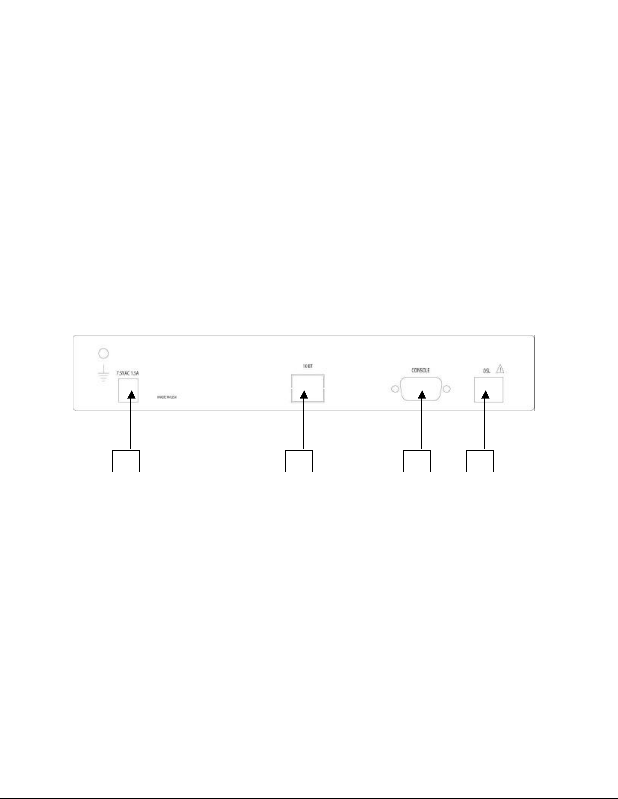
Connections......................................................................................................................................................................4
Telephone Wire Requirements......................................................................................................................................5
Installation Diagram........................................................................................................................................................6
FRONT PANEL INDICATORS ...............................................................................................................................................7
Power On...........................................................................................................................................................................7
Self-test..............................................................................................................................................................................7
LED Indication.................................................................................................................................................................7
CONFIGURING AND MONITORING A DSL LAN EXTENDER DEVICE.............................................................8
Accessing System............................................................................................................................................................8
Default Password.............................................................................................................................................................8
Main Menu........................................................................................................................................................................9
System Information.........................................................................................................................................................9
Traffic Statistics.............................................................................................................................................................10
DSLStatus/Configuration............................................................................................................................................11
Network Mode Configuration......................................................................................................................................11
Defining The Device IP Address and Subnet Mask................................................................................................13
Defining The Ethernet Side Default Gateway..........................................................................................................13
Bandwidth Management...............................................................................................................................................13
Benefits of Using The DSL LAN Extender Device As An Internet Access Gateway ......................................14
DHCP Status/Configuration.........................................................................................................................................15
SNMP Support ...............................................................................................................................................................19
MAC Address Filter......................................................................................................................................................26
Password Change...........................................................................................................................................................27
Software Upgrade..........................................................................................................................................................27

DSL LAN Extender 400 User’s Guide
© 2002 Black Box Corporation. Page v
TROUBLESHOOTING.............................................................................................................................................................30
Table 1: Troubleshooting Procedure..........................................................................................................................30
APPENDIX A: TECHNICAL SPECIFICATIONS:.........................................................................................................31
Table 2: Technical Specifications for SDSL.............................................................................................................31
Table 3: Line Rate at Different Cable Lengths for SDSL.......................................................................................31
APPENDIX B: PORT PIN LAYOUTS .................................................................................................................................32
Console (RS-232) Port Pin Layout.............................................................................................................................32
10BaseT (RJ-45) Port Pin Layout...............................................................................................................................32
xDSL Line (RJ-11) Port Pin Layout...........................................................................................................................32
APPENDIX C: DSL LAN EXTENDER ROUTING MODELS .....................................................................................33
APPENDIX D: INITIAL USE OF TELNET TO ACCESS THE DSL LAN EXTENDER DEVICE..................37
APPENDIX E: NORMAL SIGNAL-TO-NOISE RATIO TABLES .............................................................................38
USER’S REFERENCE FORM........................................................................................................................39
TECHNICAL SUPPORT INFORMATION........................................................................................................................40

DSL LAN Extender 400 User’s Guide
© 2002 Black Box Corporation Page 1
INTRODUCTION
Thank you for purchasing this outstanding Black Box communication product. This user’s guide
describes how to operate your new Symmetric Digital Subscriber Line (SDSL) device.
Instructions for installing your DSL LAN Extender devices are described in the Installation section, while
the remaining sections review operation of the DSL LAN Extender device(s) after they are installed, such
as self-test, LED indication, and troubleshooting.
PRODUCT DESCRIPTION
Black Box's DSL LAN Extender 400 is a SDSL bridge or router, which offers standard compliance high-
speed symmetrical access for Internet services with an ordinary telephone wire pair. It functions as a
remote LAN-to-LAN application.
The DSL LAN Extender 400 operates in SDSL mode with CAP encoding. In the SDSL mode, it provides
symmetrical 4.64 Mbps performance at distances up to 7,500 feet (2.28 Km) using a 26 AWG wire pair.
The DSL LAN Extender 400 provides an ideal solution for small offices and home offices (SOHO) to
reap the benefits of broadband connections to the tenant complex or neighborhood. By over subscribing
the expensive broadband connection, all tenants can share economical always-on Internet access, which
eliminates dial-up requirements, without sacrificing the individual access privacy of sharing a typical
Ethernet LAN network. It supports full IP routing for RIP-1 and RIP-2 together with the convenience of
IP address management with NAT, built-in DHCP server, and transparent Bridging.
Features
•DSL LAN Extender 400 supports SDSL with a symmetrical 4.64 Mbps rate at distances up to 7,500
feet (2.28 Km), or 144 Kbps up to 21,300 feet (6.49 Km) using a single 26 AWG telephone wire pair.
•SDSL line coding for multi-rate selection over a single copper telephone pair
•Ethernet transparent learning bridge
•IP routing with RIP-1 & RIP-2
•Network Address Translation (NAT)
•Dynamic IP assignment with DNS and gateway setting using built-in DHCP Server
•User-definable limits Separate inbound and outbound bandwidth management
•System management via console, VT 100 emulation, local and remote Telnet
•Simple Network Management Protocol (SNMP) management
•Software upgradeable over Ethernet link via TFTP or RS-232 console port
•Support for customer side Web, FTP, and E-mail Servers
•Complete power on self-test (POST)
•Standard 10BaseT Ethernet port for network connections
•System management via RS-232 console port, Telnet, and SNMP

DSL LAN Extender 400 User’s Guide
© 2002 Black Box Corporation Page 2
•Users can configure a DSL LAN Extender either as a CO (Central Office) or CP (Customer Premise)
device
•A DSL LAN Extender can automatically detect the line rate configured on the other remote DSL
LAN Extender and use the lower line rate setting of the two devices
•Stand-alone, compact design with rack-mount kit option
*Data rates achieved depend on line quality/condition and distance.
Package Contents
The list below shows what is included in your DSL LAN Extender 400 package.
•1 DSL LAN Extender 400 device
•1 Universal Power Adapter
•1 Serial Cable (DB9 Male-to-Female extension cable)
•1 DSL LAN Extender 400 User’s Guide –this booklet

DSL LAN Extender 400 User’s Guide
© 2002 Black Box Corporation Page 3
Quick Start
This section provides the basic steps to set up and configure your DSL LAN Extender devices. It is
intended for users with network experience who do not need the detailed instructions in this user’s guide
to set up and configure the DSL LAN Extender 400.
You must perform the steps below for both the DSL LAN Extender CO and CP devices.
1. Connect the DSL LAN Extender device to your network (LAN) via its 10BaseT port.
2. Connect the DSL LAN Extender device to the DSL line via its Line port.
3. Attach the serial cable to the serial (COM) port on a PC; attach the other end to the DSL LAN
Extender device’s Console (RS-232) port.
4. Connect the power adapter to a grounded outlet and insert the power jack into the DSL LAN Extender
device’s power port. The LEDs on the device’s front panel should flash while the device performs its
startup diagnostic tests.
5. Configure the following settings for a terminal-emulation program (ProComm Plus recommended) on
the PC connected to the DSL LAN Extender device’s Console port:
•Data rate: Specify console data rate up to 38400; the DSL LAN EXTENDER device will
automatically adapt to the rate you specify
•Terminal type: VT 100
•Data bits: 8
•Parity bits: None
•Stop bits: 1
•Flow Control: None
6. Hit the <Enter> key after you connect the PC to DSL LAN Extender device, the main menu will
appear. Select the DSL Status/Configuration option from the Main Menu. When prompted for the
password, enter <password>.
7. One of the DSL LAN Extender device is pre-configured as CO and the other device is pre-configured
as CP. Select the DSL Status/Configuration menu option to change the configuration to either CO or
CP.
8. The device is pre-configured with the highest allowed line rate. For the CO device, use the Line Rate
selection option to select successively lower line rates until the two devices link up. You do not need
to change the line rate defined for the CP device, as it will automatically adapt to the rate selected for
the CO device.
9. Select the Network Mode Configuration option from the Main Menu.
Define the setting of Bridging Enabled and RIP Enabled functions. If RIP is enabled, then select
Device Main IP Address and its Subnet Mask address. It is optional to define the Default Gateway.
10. Set the Bandwidth Management for Outbound and Inbound traffic rates in Kbps. (A setting of 0 is
equivalent to NO bandwidth control)
11. For CP devices only, the NAT enabled option can be activated. Define the subscriber’s IP address for
NAT and its subnet mask.
12. Configure the optional IP addresses for E-mail server and HTTP/FTP server.
13. Select DHCP Status/Configuration option from the Main Menu to configure IP address range for
DHCP and DNS servers.

DSL LAN Extender 400 User’s Guide
© 2002 Black Box Corporation Page 4
INSTALLATION
To install your DSL LAN Extender 400 devices, you need to use the following cable connection for each
device:
•Supplied DC power adapter
•10BaseT Ethernet cable
•DSL telephone cable
•Serial cable –you only need to connect a serial cable if you want to configure the DSL LAN
Extender device via a serial port connection.
•Please see the section below for Port Pin Layout of Console (RS-232), 10BaseT, and DSL LINE
ports.
The illustration below shows the ports on the DSL LAN Extender 400’s rear panel to which you connect
the cables.
Connections
(1) DC power adapter terminal. Connect this terminal with the power jack from the supplied DC power
adapter.
(2) LAN Network Port: Standard 10BaseT Ethernet interface port (RJ-45 Jack).
(3) Console Port, RS-232 (DB9 Female Connector): Console serial port for system configuration.
(4) xDSL Line Interface: Standard RJ-11 Jack (using Pins 3 and 4).
1.
3.
2.
4.

DSL LAN Extender 400 User’s Guide
© 2002 Black Box Corporation Page 5
Telephone Wire Requirements
The telephone circuits recommended for the DSL LAN Extender 400 are commonly known as Dry Line,
Dry Pair, Raw Copper Line, or Alarm Circuit. Now, it is often referred as DSL Line.
When ordering a DSL line from a Telco, make sure to tell the telephone company that you need a non-
loaded line with no bridged taps on it. For example, Pacific Bell’s Local Area Data Channels (LADC)
uses USOC code to specify a 2-wire dry line as “T6E2D”.
Note:
The term “non-loaded” or “non-loaded coils” means no passive low pass filter for voice spectrum on the
line. With a low pass filter, the loop is used for voice signals only, the high frequency spectrum of signals
(above 4Khz) will be filtered out, and the loop cannot be used for xDSL signal transmission.
To have a dry line from a Telco, the loaded coils in the Telco’s Central Office and bridge taps at punch
down blocks MUST BE REMOVED from the subscribed line.

DSL LAN Extender 400 User’s Guide
© 2002 Black Box Corporation Page 6
Installation Diagram

DSL LAN Extender 400 User’s Guide
© 2002 Black Box Corporation Page 7
FRONT PANEL INDICATORS
Power On
Check all connections before plugging in the power jack from the supplied DC power adapter. Then
attach the adapter to the wall outlet or other AC source. Be sure the AC voltage is correct for the AC
power source of 90V~230VAC at 60Hz.
Self-test
When the DSL LAN Extender device is turned on, it performs a self-test, which may take a few seconds.
During this period, both Yellow LEDs are on. After the self-test is complete, the DSL Yellow LED
flashes indicate device is configured as CO. The DSL Yellow LED is off indicates device is configured as
CP. And the Green LED will be on after the self-test. The DSL LAN Extender device is then ready to
operate.
LED Indication
System: RUN –steady Green LED indicates device is at operational status
DSL –steady Yellow LED indicates DSL link is up
-flashing momentarily Yellow LED before link up, indicates device is configured as
CO
-Yellow LED off indicates device is configured as CP
Link: LAN –steady Yellow LED indicates Ethernet link is up
Alarm –steady/flashing Red LED indicates error/noise occurred/received during
transmission.

DSL LAN Extender 400 User’s Guide
© 2002 Black Box Corporation Page 8
CONFIGURING AND MONITORING A DSL LAN EXTENDER
DEVICE
Accessing System
Access to the System Management Main Menu can be done either through a Console Port or LAN Port
(Telnet):
•CONSOLE PORT–The console port is located at the rear panel of all Black Box’s DSL LAN
Extender devices. Console connection is through an RS-232 DB9 cable to the terminal/computer’s
serial COM ports. Users may choose to use any terminal emulation software (PROCOMM Plus is
recommended).
Note: Hardware flow control should be disabled and S/W download via HyperTerminal is NOT
supported.
•TELNET –Once the IP Address is assigned to the DSL LAN Extender device, users can “Telnet” to
the DSL LAN Extender device remotely for system configuration. An appropriate IP address must be
configured to the DSL LAN Extender device through a console terminal before the telnet command
can be used.
Default Password
The password is required to access any of the Main Menu’s sub-menus. You will need to re-enter the
password each time the device is reboot or connection is timed out. The default password is set to
“password”. You may change the password in the main menu.
Please Enter Password :
Press Esc to return to the main menu

DSL LAN Extender 400 User’s Guide
© 2002 Black Box Corporation Page 9
Main Menu
After entering the correct password, the following message is displayed. Select the desired function by
entering the corresponding number.
System Information
-System Name: This allows the user to give the DSL LAN Extender a System Name.
-Security Level: This permits the user to set the security level to high or low by pressing <Enter>. If
security level is set to "High", the Main Menu cannot be accessed without the correct password.
-Allow TFTP Download: This allows the user to enable or disable software upgrades through TFTP.
-The Device Configured as: This indicates if the device is configured as a CO (Central Office or
Central Unit) or a CP (Customer Premise or Remote Unit) device.
-The next four lines display the currently assigned MAC Address, Device Main IP Address, Controller
Serial No., and Controller HW Version respectively.
-Software Version: This indicates the current software version of the.
-Software Checksum: You should record this checksum and compare it with the displayed one every
time the device is reset or power-cycled. This checksum should be the same; if it changes, the
device’s software has been corrupted. In this case you will have to reload the software. Please note
that each new software version has a different checksum.
Copyright (C) 2002, Black
Box Corporation, Inc.
Main Menu
1. System Information
2. Traffic Statistics
3. DSL Status/Configuration
4. Network Mode Configuration
5. DHCP Status/Configuration
6. SNMP Configuration
7. MAC Address Filter
8. Password Change
9. Software Upgrade
A. System Reboot
B. Set Factory Default
0. Exit
Make A Choice :
Tab : Move to next changeable field
Up/down Arrow : Move cursor by one line
Left/right Arrow: Move cursor by one character
Space/enter : Next choice when in selection field
Ctrl-S : Save all changes of current screen
Esc : Leave current table or screen

DSL LAN Extender 400 User’s Guide
© 2002 Black Box Corporation Page 10
Traffic Statistics
The sub-menu 2 in the Main Menu provides traffic statistics from/to the Ethernet port and from/to the
DSL port.
•Ethernet Packets Received: Number of Ethernet packets that have been received from the LAN
•Ethernet Packets Sent: Number of Ethernet packets that have been sent to the LAN
•Ethernet Tx+Rx Errors: Number of Ethernet packets received or transmitted on the Ethernet port
that have errors
•DSL Line Packets Received: Number of packets from the remote LAN that have been received
from the DSL line
•DSL Line Packets Sent: Number of packets from the directly connected LAN that have been sent
onto the DSL line
•DSL Line RX Packets Errors: Number of packets received from the DSL line that have errors
•Current Error displays any error that the device may have at that time
===== System Information =====
. System Name :
. Security Level : Low
. Allow TFTP Download : N
. The Device Configured as : CP
. MAC Address : 00 E0 F3 00 05 14
. Device Main IP Address : 192.168.100.001
. Controller Serial No. : 00C09C84D30E
. Controller HW Version : 1
. Software Version : Ag400 SDSL 1.21
. Software Checksum : 7B5C
Ctrl-s Save all
Press Esc to return to the main menu
===== Traffic Statistics =====
. Ethernet Packets Received : 375
. Ethernet Packets Sent : 375
. Ethernet Tx+Rx Errors : 0
. DSL Line Packets Received : 375
. DSL Line Packets Sent : 375
. DSL Line Rx Packet Errors : 0
. Current Error: (no error)
Press '0' to reset the traffic statistics.
Press Esc to return to the main menu

DSL LAN Extender 400 User’s Guide
© 2002 Black Box Corporation Page 11
DSL Status/Configuration
You use the DSL Status/Configuration screen to configure a DSL LAN Extender device as either the CO
or CP device. This screen also allows you to define the DSL line rate and displays information about the
status of the DSL connection, including the operation mode of CO or CP, whether the link is up or down,
line rate selected (Kbps), actual line rate (Kbps), and the signal-to-noise ratio (SNR) of the DSL line (dB).
-The Device can be changed to either CO or CP by pressing <Enter> and toggling between the two.
Note: The devices work only in pairs, with one configured as CO and the other as CP. This is
already factory defaulted. This function can be used for devices that are not configured
appropriately.
-The Line Rate can be changed by using the arrow keys to get to the Line Rate Selection line. Press the
<Enter> or <Space> key to select the appropriate line rate. There are 10 selectable line rate settings
for SDSL: 4640, 2320, 2064, 1552, 1040, 784, 528, 400, 272, and 144 Kbps.
-The “Actual line rate” shows the actual line rate (Kbps) in effect on the DSL line. When you connect
the CO device to a CP device, they will link up with the lower line rate settings of the two devices.
-Link Status is shown as UP or DOWN when CO and CP devices are linked up or linked down.
-DSL Line SNR (dB) shows the signal-to-noise ratio in Decibels for the received signal on the DSL
line. The normal values for 24 AWG and 26 AWG wire pairs are shown in Appendix E.
-Note: You must press <Ctrl-s> to save all changes.
Network Mode Configuration
The Network Mode Configuration screen allows the user to change a variety of functions.
-The user can enable either or both Bridging and RIP functions.
-The user can change the devices main IP Address, Subnet Mask and Default Gateway.
-A Bandwidth Limit can also be set for inbound and outbound traffic (a setting of 0 means that the
traffic control is not activated and it will allow whatever traffic the network can support).
-For the Remote CP device, NAT or Router feature can be enabled, with optional setting for e-mail
and http/ftp servers. The appropriate IP addresses must be entered.
===== DSL Status/C
onfiguration =====
. The Device Configured as : CP Link Status : Down
. Line Rate Selection(Kbps) : 4640
. Actual Line Rate(Kbps) : 0
(lower rate set by other sides)
. DSL Line SNR(dB) : 0.0
Ctrl-s Save all
Press Esc to return to the main menu

DSL LAN Extender 400 User’s Guide
© 2002 Black Box Corporation Page 12
Network Mode Configuration -Local (CO) Side
Network Mode Configuration –Remote (CP) Side
By default, the DSL LAN Extender CO and CP devices are pre-assigned the same IP address at the
factory: 192.168.100.1. You should assign the DSL LAN Extender device a valid host IP address in the
same sub-network as the Ethernet to which it is directly connected.
To configure the DSL LAN Extender without using a serial port, please see Appendix D.
===== Network Mode Configuration =====
. Device Serves at Side : CO
. Router Enabled : N
. Bridging Enabled : Y
. RIP Enabled : N
. Device Main IP Address : 192.168.100. 1
. Device Main IP Subnet Mask : 255.255.255. 0
. Ethernet Side Default Gateway : 0. 0. 0. 0
. Bandwidth Limit, Outbound(Kbit/s): 0
. Bandwidth Limit, Inbound(Kbit/s) : 0
Ctrl-s Save all
Press Esc to return to the main menu
===== Network Mode Configuration =====
. Device Serves at Side : CP
. Router Enabled : N
. Bridging Enabled : Y
. RIP Enabled : N
. Device Main IP Address : 192.168.100. 1
. Device Main IP Subnet Mask : 255.255.255. 0
. Ethernet Side Default Gateway : 0. 0. 0. 0
. NAT/Router Enabled : N
(Items below have no effect unless NAT/Router is enabled)
. Subscriber IP Address : 0. 0. 0. 0
. Subscriber Subnet Mask : 0. 0. 0. 0
. E-mail Server Enabled : N
. E-mail Server's IP Address : 255.255.255. 0
. HTTP/FTP Server's IP Address : 0. 0. 0. 0
Ctrl-s Save all
Press Esc to return to the main menu

DSL LAN Extender 400 User’s Guide
© 2002 Black Box Corporation Page 13
Defining The Device IP Address and Subnet Mask
This option lets you define the IP address for the DSL LAN Extender CP device’s connection to your
local LAN. Assign the DSL LAN Extender CP device a valid host IP address that is consistent with the
Ethernet to which it is directly connected. Also, make sure the DSL LAN Extender CP device belongs to
the same sub-network as the Ethernet to which it is directly connected. See the illustration at the end of
this section for an example showing IP addresses correctly assigned on a network.
You use this option to specify how many bits in an IP address are considered to be part of the network
portion of the address. For example, the default Device Main IP Subnet Mask, 255.255.255.0, indicates
that 24 bits are used for the network portion, leaving 8 bits, or a maximum of 254 node addresses, for this
sub-network to use. If you do not expect your organization to require more than 254 nodes in the future,
you should leave the default value for this option.
Defining The Ethernet Side Default Gateway
You use this option to specify the default gateway address of the Internet access router or other router
connected to DSL LAN Extender Ethernet port. Please see Appendix C for examples of setting the IP
parameters for different network environments.
Bandwidth Management
The bandwidth management feature allows you to manage bandwidth from the CO device. Inbound
bandwidth management refers to traffic going into the Ethernet port of the CO device. And outbound
bandwidth management refers to traffic going out of the Ethernet port of the CO device. In a typical
Internet access application, users who mostly download information (from the Web, for example) would
probably want to increase the amount of inbound traffic. On the other hand, if some users were hosting
their own Web site, most traffic would flow out from their computers, so they would probably want to
increase the amount of outbound traffic. The inbound and outbound settings function independently.
Bandwidth management feature allows ISPs to charge their customers based on the customers’ bandwidth
needs. It also allows ISPs to increase users’ bandwidth allocation quickly and easily, without requiring
additional hardware or software. In addition, bandwidth management allows users to reconfigure the
bandwidth without reconfiguring the line rate. Bandwidth management will not exceed the line rate that
the device is connected at. The maximum setting for bandwidth management will equal the connected line
rate.
To define the desired amount of bandwidth for outbound traffic (that is, traffic flowing out of the Ethernet
port of the CO device), enter the desired bandwidth in the Outbound Bandwidth Mgmt. field. The number
you enter represents the number of kilobits per second (Kbps). The valid range for this field is 1 to x,
where x is the highest data rate supported by the DSL LAN Extender device in its current configuration.
To define the desired amount of bandwidth for inbound traffic (that is, traffic flowing into the Ethernet
port of the CO device), enter the desired bandwidth (in Kbps) in the Inbound Bandwidth Mgmt. field. The
valid range for this field is 1 to x, where x is the highest line rate supported by the DSL LAN Extender
device in its current configuration.
Note:To turn off bandwidth management in both directions, specify 0 for both the Inbound and
Outbound Bandwidth Mgmt. fields. To turn off bandwidth management in either the outbound or
inbound direction, specify 0 for the Outbound or Inbound field, depending on the direction you
want. Specifying 0 indicates NO bandwidth management.
Press <Ctrl-s> to save the new setting.

DSL LAN Extender 400 User’s Guide
© 2002 Black Box Corporation Page 14
Note: When using bandwidth management, configure the DSL LAN Extender device for the highest
line rate supported by the length and condition of the DSL cable.
Benefits of Using The DSL LAN Extender Device As An Internet Access
Gateway
You can configure a DSL LAN Extender CP with Bridging disabled and RIP either enabled or disabled.
In this mode, the DSL LAN Extender will act as an Internet access gateway, which treats the local LAN
side as one community. A good example of how this works is in a high-rise apartment building. You
could connect the residents on each floor to a DSL LAN Extender CP device. Each DSL LAN Extender
device, in turn, would connect to a DSL LAN Extender CO device.
Network Address Translation (NAT)
This option allows a group of computers connected to a DSL LAN Extender CP device to share a single
IP address, while still allowing the machines to use different private, internal IP addresses. This feature is
useful in situations where users are restricted by a limited (and usually small) number of public IP
addresses assigned by their Internet Service Provider (ISP). For example, by setting the Ethernet Side
Subnet Mask to 255.255.255.0, users have the flexibility of using 254 private, internal IP addresses for
their machines. Yet with NAT turned on, the outside world only sees one, public IP address (the DSL side
IP address) for all the machines.
The NAT option also enhances the security of your network because only a single IP address is presented
to the world, not every computer’s IP address. This makes it harder for hackers to access the computers
on your network.
To turn on the NAT feature, select Y for the NAT Enabled option and enter the NAT IP address (such as
192.168.10.10) and its Subnet Mask (such as 255.255.255.0).
The CP routing configuration allows public IP addresses to co-exist with the sub-network that uses
private IP addresses. When the ISP has assigned more than one public IP address, you can use them for
the E-mail server and or the HTTP/FTP server. Please see Appendix C for more detailed examples.
Adding Support for Your E-Mail Server and HTTP/FTP Server
The DSL LAN Extender CP device supports the Simple Mail Transfer Protocol (SMTP) and Post Office
Protocol 3 (POP3). If you have an e-mail server on your local LAN to handle your organization’s e-mail,
you can configure the DSL LAN Extender CP device to support this server. The advantages of setting up
your own e-mail server are as follows:
•Reduce Internet traffic across the DSL connection. E-mail messages directed to PCs on the local LAN
aren’t sent across to the remote side. Also, when people on the local LAN side check their e-mail,
their queries are sent to the local e-mail server, instead of over the DSL connection.
•Provide flexibility in managing e-mail accounts. You can quickly and easily add, delete, or modify e-
mail accounts by yourself.
•Provide greater security for internal e-mail.
To use an E-mail server, select Y for the E-Mail Server Enabled option. Enter the E-mail server’s IP
address. If you have a HTTP/FTP server, you can also enter its IP address in the next field.
Table of contents
Other Black Box Network Card manuals

Black Box
Black Box LH1690C-LC-R2 User manual

Black Box
Black Box PC118C-R2 User manual

Black Box
Black Box LH3000 User manual

Black Box
Black Box LCL931A User manual

Black Box
Black Box DSL LAN Extender 200 User manual

Black Box
Black Box CityLIGHT LCL533A User manual

Black Box
Black Box LE7005A-UTP-R2 User manual

Black Box
Black Box LH1660C-SC User manual

Black Box
Black Box LE7003A User manual

Black Box
Black Box ME0001C-10BT User manual